1
Alive Stack User Manual
Living Machines Group
February 10, 2003
1
1 Overview
This document provides specication for the use and design of the Alive Stack. This document,
supporting code, and schematics can be found at ~limanalivenstack on the MIT AI Lab network.
2 Stack for Windows
The Alive Stack can be monitored and debugged via a graphical user interface. This user interface
is documented in the Creature Language manual. A Windows port of the interface is available at
xxx. However, the following additional steps are necessary before the Windows port can be used:
1. Install the latest version of Cygwin to the host PC (a Unix for Windows toolset): http://www.cygwin.com/
(a) During installation, be sure that the X Server XFree86 is also installed.
2.
3 Pic Programming
The Warp13a Pic programmer (www.newfoundelectronics.com) is currently the default programmer
for the Alive Stack, due mostly to its command-line interface, availability for Linux, and its integration into the CCS Pic-C compiler environment and the MPLAB environment. However, other
programmers should work equally well. Programming is done via the In-Circuit-Serial-Programmer
(ICSP) and is not done via Low-Voltage-Programming. The standard CONFIG settings for Pic
programming we use are cong word 0x3F32, which corresponds to:
1. Watchdog Timer: O
2. Low-Voltage Programmer: O
3. Power-up Timer: On
4. Brownout Detect: O
5. Crystal select: HS (20Mhz)
6. Code Data Protect: O
7. Flash Program Memory: On
2
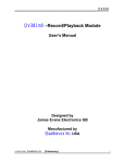
Hirose MQ172X-4SA-CV
4-pin connector
Molex
5-pin connector
NC
Gnd
Vpp
Rb7
Rb6
Pin4: Rb7
Pin3: Rb6
Pin2: Vpp
Pin 1: GND
Figure 1: Programming cable pinout for Warp13 programmer.
8. Flash Debug Mode: O
Each peripheral device will need the rmware downloaded to it. The rmware is written in assembly
and/or in CCS Pic-C. Each peripheral device in the stack needs one or more unique IDs. This should
be set in the rmware, the rmware recompiled, and programmed to the peripheral device. Refer
to the rmware for setting the device ID.
4 Timing and Memory Considerations
Bandwidth and memory constraints place some limitations on the Alive Stack. The communication
speed between the Rabbit (or host PC) and the Alive Stack is 115:2K bps. The Creal bios sends
update data packets to the Alive Stack at a rate of 64H z . To satisfy this polling rate, the Alive Stack
can only support approximately 115200=10=64 = 180 total bytes for the upstream and downstream
packet size (fast and slow packet combined).
The implementation of the communication protocol on the Carrier Board imposes a memory constraint on the system. The downstream packets are buered on the Carrier Board. This buer size
is limited to 256 bytes. Because of the Rabbit /Alive Stack bandwidth constraint, this limitation
can eectively be ignored. Memory constraints also limit the total number of peripheral devices on
the Alive Stack to be 32.
3
Communication between the Carrier Board and the peripheral devices on the Alive Stack occurs
at 250K bps. It is important to keep this in mind when designing a peripheral board. The typical
peripheral board uses a 20Mhz Pic16F876, which has an instruction cycle time of 0:2us. The time
between two successive bytes arriving on the peripherals UART is 11=250000 = 44us. Thus the
peripheral has approximately 200 instruction cycles to perform communciation housekeeping and
to implement the desired peripheral functionality.
5 Peripheral Board Design
A peripheral board designed to t into the Alive Stack should conform to the current Alive Stack
form-factor and footprint. A template PCB layout is available. The RS 485 bus, programming
header, and auxillary power connectors have been standardized and all future peripherals should
use these connectors. In addition, to maintain clearance between adjacent boards in the Alive
Stack, we follow the convention that tall board components should be placed on the bottom of the
board. For example, all programming headers and power conectors should be on the bottom of the
board.
The top edge of the Alive Stack (the edge with the mounting hole) is the breakout for the programming header and auxillary power connectors. The location of these connectors should follow
the existing standard as best possible. The two side (short) edges provide breakout for i/o, etc.
The bottom edge shouldn't be used for breakout so that it can mount against the robot.
Refer to the periph template.ddb Protel document for a template design when designing new
board. Likewise, refer to periph template.c when designing new board rmware.
6 Board Specications
6.1
Carrier Board
6.1.1 Overview
The Carrier Board provides an interface between the host and the peripheral boards. The two onboard Pic 16F876 microcontrollers implement the Alive Stack communication protocol as specied
in the Creal Communication Protocol documentation. Typically the host will be a Rabbit microcontroller running Creal. In this case, the details of the protocol are not important as the Creal
Bios will take care of communication between the Rabbit and the Carrier Board. Alternatively,
a host PC may be interfaced with the Alive Stack using the RS232 Board. In this case, it is the
responsibility of the host PC to handle communication with the Carrier Board.
4
6.1.2 Connectors
J6 Master Programming Header
Uses standard programming connector:
Programs alive master.c Carrier Board rmware
Pin
Denition
1
2
3
4
GND
12V Prgm Voltage (VPP)
RB6 In Circuit Prgm
RB7 In Circuit Prgm
J7 Slave Programming Header
Uses standard programming connector:
Programs alive slave.c Carrier Board rmware
Pin Denition
1
2
3
4
GND
12V Prgm Voltage (VPP)
RB6 In Circuit Prgm
RB7 In Circuit Prgm
J3 Serial Port C Header
J2 Serial Port D Header
Pin Denition
Pin Denition
Breaks out Rabbit Serial Port C Breaks out Rabbit Serial Port D
2mm pitch standard header
2mm pitch standard header
1
2
3
4
GND
RX
VCC
TX
1
2
3
4
J4,J5
Rabbit Header
GND
RX
VCC
TX
Mates with Rabbit Micro
Align Rabbit mounting hole with Carrier
Pin
Denition
Board
mounting hole.
J4: 1-26 Refer to Rabbit documentation for J4 pinout
J5: 1-26 Refer to Rabbit documentation for J5 pinout
6.1.3 Packets
The
Carrier Board
Protocol
recieves data packets from the host according to the
. It replies with continuous stream of data packets from the
Creal Communication Protocol
documentation for more information.
5
Creal Communication
. Refer to the
Alive Stack
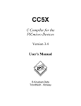
J5
J4
Top Side
Master
Slave
Bus
Bottom Side
(Viewed through top)
4
3
2
1
Serial C
J2
4
3
2
1
Serial D
4321
4321
J7
J6
Figure 2:
J3
Carrier Board
Pinout
6.1.4 Power
The Carrier
Board
is powered by the Alive
Stack
bus. It draws xx mA.
6.1.5 Firmware
There are two onboard Pics, denoted Master and Slave. They are programmed with alive master.c
and alive slave.c respectively. Excepting upgrades in rmware, these should not need reprogramming once initially programmed.
6.1.6 Notes
1. The Carrier Board places some memory constraints on total packet size on the
Refer to nreffg for more information.
.
Alive Stack
2. The Master heartbeat LED should be blue and the Slave heartbeat LED should be orange.
3. At startup, the Carrier Board 's Master heartbeat LED will ash rapidly. When table initialization has occured via the Rabbit, the LED will ash at half its previous speed.
6
6.1.7
Power Board
6.1.8 Overview
The Power Board sits at the bottom of the Alive Stack. It provides power to the Alive Stack bus
which in turn powers most all of the electronics on the Alive Stack. Two options of power are
available. One is an optoisolated DC-DC 5V dc converter which is recommended. A second option
is a 5V dc voltage regulator which is not optoisolated. On board jumpers select which option is to
be used. While the Power Board can be populated with both power options, only one is necessary.
The 5V dc voltage regulator is a less expensive, more compact, and more readily available option
while the DC-DC converter provides power source noise isolation. The Power Board also contains
test points for debugging, a power/reset switch, and terminating resistors for the RS 485 bus.
6.1.9 Connectors
J2 Power Header
See Power section for spec.
2mm discrete wire header
Pin Denition
1
2
Alive Stack
Alive Stack
GND
PWR
J3-J6 Test Points
Pin Denition
J3
J4
J5
J6
GND
Alive Stack Vcc
RS 485 Bus TX from Rabbit /Host
RS 485 Bus RX from Rabbit /Host
Alive Stack
6.1.10 Power
Power Specications
Supply
Input
Output Current Mfg
Part #
Regulated
6-24Vdc 5Vdc
500ma National Sem. LM2937
DC-DC Converter 9-18Vdc 5Vdc
1000ma Tri-Mag
TDB5W-1205S
Refer to the datasheet for each component for more information.
7
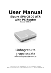
Bus
Top Side
Optoisolated Jumper Sttings
Bottom Side
(Viewed through top)
Vcc TX
RX GND
Figure 3:
Regulator Jumper Settings
J2
Power Board
pinout.
The Alive Stack power consumption characteristics are...
6.1.11 Notes
6.2
RC Servo Board
6.2.1 Overview
The RC Servo Board controls up to 8 RC servos using pulse-code-modulation. The board uses
standard 0:1" inch 3 pin connectors that are pin compatible with most servos.
8
6.2.2 Connectors
J2 Programming Header
Uses standard programming connector
Programs alive servo periph.c board rmware
Pin Denition
1
2
3
4
GND
12V Prgm Voltage (VPP)
RB6 In Circuit Prgm
RB7 In Circuit Prgm
J7-J10 Servo Header
Breaks out 8 Servo Channels
0:1in pitch standard header
Each set of 3 pins controls 1 RC Servo.
Pin
Denition
1
2
3
GND
PWR
Signal
J6 Power Header
External Servo Power ( 4:5
2mm discrete wire header
6V dc)
Pin Denition
1
2
Servo Power
Servo GND
6.2.3 Packets
Downstream Packet Upstream Packet
Byte Denition
Byte Denition
0
1
2
3
4
5
6
7
8
Periph ID
Ch1 Pos
Ch2 Pos
Ch3 Pos
Ch4 Pos
Ch5 Pos
Ch6 Pos
Ch7 Pos
Ch8 Pos
There is no upstream data
9
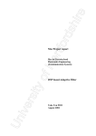
Top Side
Bus
S1
1
2
3
1
2
3
S5
S3
1
2
3
1
2
3
S7
Bottom Side
(Viewed through top)
Bus
S2
1
2
3
S4
1
2
3
4321
J6
Figure 4:
1
2
3
S6
1
2
3
S8
RC Servo Board
Pinout
6.2.4 Power
The RC Servo Board electronics are powered by the Alive Stack bus. It draws xx mA. The RC
servo power is provided externally. This external power supply is optoisolated from the Alive Stack
power. It should match the specications provided by the servo vendor, but is usually in the range
of 4:5 6:0V dc
6.2.5 Firmware
The RC Servo Board should be programmed with alive servo periph.c. The position of an RC
servo is specied by an 8 bit number. The rmware may soon be upgraded to provide 12 bit
resoultion. This positional value is translated in the rmware into a Pulse-Code-Modulation pulse
width. Typically, this pulse width has a range of 1 2ms which corresponds to a physical range of
0 90 degrees. However, these number vary between manufacturers and greater ranges up to 180
degrees can be obtained by tuning the pulse width range in rmware. Refer to alive servo periph.c
for an example of how to do this. The peripheral may be either fast or slow. In Creal, a typical
denition might look like:
\texttt{(defperipheral servoboard :fast:id 1 :default-type :uns8 :write }
\texttt{((ch1 128)(ch2 128)(ch3 128)(ch4 128) (ch5 128)(ch6 128)(ch7 128)(ch8 128)))}
10
6.2.6 Notes
1. At startup, the default servo position is dead-center, corresponding to a positional value of
128:
2. Care should be taken that the servo connector is not installed backwards. Refer to the board
diagram nreffg and the board silkscreen to ensure proper orientation.
6.2.7
Analog Sensor Board
6.2.8 Overview
The Analog Sensor Board interfaces with up to 16 sensors. The onboard ADC provides 12 bit
sampling resolution on voltages 0 5V dc. Sensor wiring is simplifed by provision of indvidual
GN D and 5V dc P W R pins for each input channel. An external power supply is required however.
6.2.9 Connectors
J2 Programming Header
Uses standard programming connector:
Programs alive analog periph.c board rmware
Pin Denition
1
2
3
4
GND
12V Prgm Voltage (VPP)
RB6 In Circuit Prgm
RB7 In Circuit Prgm
J4,J5 Sensor Header
Breaks out 16 Sensor Channels
0:2mm pitch header
Recommended connector:
Molex 2mm crimp housing: 51110-0650
Each set of 3 pins provides a sensor channel.
Pin
1
2
3
Denition
GND
Signal
PWR
11
J3 Power Header
External Sensor Power ( 5:0V dc)
2mm discrete wire header
Pin Denition
1
2
Sensor Power
Sensor GND
6.2.10 Packets
Each channel returns 2 bytes of data. The ADC provides 12 bit resoultion. The upper 4 bits of
the most signcant byte (MSB) are set to 0.
Downstream Packet
Byte Denition
0
Periph ID
Upstream Packet
Reply from periph ID A
Byte Denition Byte Denition
0
1
2
3
4
5
6
7
Ch1 MSB
Ch1 LSB
Ch2 MSB
Ch2 LSB
Ch3 MSB
Ch3 LSB
Ch4 MSB
Ch4 LSB
8
9
10
11
12
13
14
15
Ch5 MSB
Ch5 LSB
Ch6 MSB
Ch6 LSB
Ch7 MSB
Ch7 LSB
Ch8 MSB
Ch8 LSB
Upstream Packet
Reply from periph ID B
Byte Denition Byte Denition
0
1
2
3
4
5
6
7
Ch9 MSB
Ch9 LSB
Ch10 MSB
Ch10 LSB
Ch11 MSB
Ch11 LSB
Ch12 MSB
Ch12 LSB
8
9
10
11
12
13
14
15
Ch13 MSB
Ch13 LSB
Ch14 MSB
Ch14 LSB
Ch15 MSB
Ch15 LSB
Ch16 MSB
Ch16 LSB
12
1
2
3
Ch7
1
2
3
Ch5
Ch13
1
2
3
1
2
3
Ch3
Ch15
1
2
3
1
2
3
Ch1
Ch10
1
2
3
1
2
3
Ch8
Ch12
1
2
3
1
2
3
Ch6
Ch14
1
2
3
1
2
3
Ch4
Ch16
1
2
3
1
2
3
Ch2
Ch9
1
2
3
Ch11
1
2
3
Bus
Top Side
Bus
Bottom Side
(Viewed through top)
4321
J2
J3
Pin1: Gnd
Pin2: Signal
Pin3: Pwr
Signal Pulldown
1206 Resistor
Signal Pullup
1206 Resistor
Figure 5: Analog Sensor Board pinout. Signal pullup/pulldown can be achieved by soldering a
1206 package resistor across 2 header pins as illustrated.
6.2.11 Power
The Analog Sensor Board electronics are powered by the Alive Stack bus. It draws xx mA. The
sensor power is provided externally This external power supply is not optoisolated from the Alive
Stack power. It should be a clean, regulated supply of 5:0V dc:
6.2.12 Firmware
The Analog Sensor Board should be programmed with alive anlog periph.c. The rmware treats
the board as two independent peripheral devices of 8 channels each. Consequently, two peripheral
IDs need be specied in the rmware. If 8 or less sensor channels are used, then only one peripheral
need be specied in Creal. The peripheral may be either fast or slow. In Creal, a typical denition
might look like:
(defperipheral sensor_bank_a :fast :id 1 :read
(adc1 adc2 adc3 adc4 adc5 adc6 adc7 adc8))
(defperipheral sensor_bank_b :fast :id 2 :read
(adc9 adc10 adc11 adc12 adc13 adc14 adc15 adc16)))
13
6.2.13 Notes
6.3
RS232 Board
6.3.1 Overview
The
allows the Alive Stack to be used with a host PC instead of the Rabbit. The
matches the header footprint of the Rabbit such that it can be plugged into the
Carrier Board where the Rabbit normally resides. The RS232 Board provides RS 485
RS 232
conversion between the Alive Stack and the host PC's serial port.
RS232 Board
RS232 Board
6.3.2 Notes
1. This current version of this board is not compatible with the latest version of the Alive Stack.
To be done soon...
7 Schematics
8 Parts Lists
9 Vendors
14