1
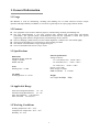
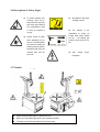
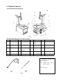
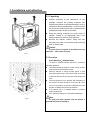
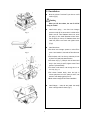
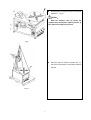
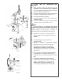
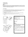
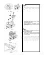
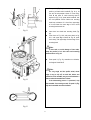
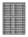
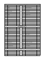
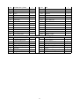
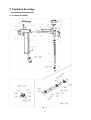
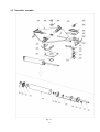
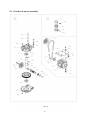
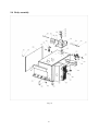
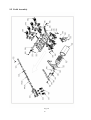
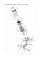
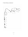
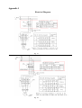
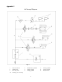
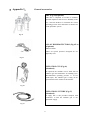
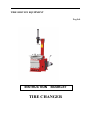
TIRE SERVICE EQUIPMENT English INSTRUCTION BOOKLET TIRE CHANGER Safety Precautions WARNING Note This manual is a necessary part of the product. Please read carefully. Keep the manual for later use when maintaining the machine. This machine can only be used for the designated purposes. Never use it for any other purpose. The manufacturer is not responsible for the damage incurred by improper use or use other than the intended purpose. Precautions The equipment can only be operated by qualified personnel with special training. Modification to any components or parts, or use the machine for other purpose without either obtaining the agreement from the producer, or observing the requirement of the instructions may lead to direct or indirect damage to the equipment. The equipment should be installed on the stable ground. Keep the back panel 0.5M away from the wall for good ventilation. Enough room should be left on both sides for convenient operation. Do not put the equipment a place with high temperature or moisture, or near the heating system, water tap, air-humidifier or chimney. Do not put the equipment near the window with sunlight. Protect the unit with a curtain or shield if necessary. Avoid lots of dust, ammonia, alcohol, thinner or spraying binder. People who are no operating the machines should be kept away when it is used. Use appropriate equipment and tools, protective and safety equipment, including eyeglasses, earplugs and working boots. Pay special attention to the marks on the machine. Do not touch or approach the moving parts by hand during operating. Do not remove the safety device or keep it from working properly. Use #2 lithium lubricants (grease) only within the safety range. Refer the appendix for the safety data. Before moving the tire changer, contact maintenance personnel. Table of Contents Safety Precautions……………................………………………………………………………1 1. General Information…………..........…………………………………………………………3 1.1 Usage……………………………………………....………………………………………………… 3 1.2 Features ……………………………………………………………………………………… 3 1.3 Specifications……………………………………………………………………………………… 3 1.4 Applicable Range………………………………………………………………………………… 3 1.5 Working Conditions ………………………………………………………………………… 3 1.6 Description of Safety Signs…………………………………………………………………… 4 1.7 Position of Safety Signs…………………............………………………………………………… 4 2. Main Structure…………….......................……………………………………………………5 3. Installation and adjusting………………………………………………………………… 6 3.1 Unpacking…………………………………………………………………………………………… 6 3.2 Location ……………………………………………………………………………………… 6 3.3 Installation…………………………………………………………………………………………… 7 3.4 Power and Air Connections and Regulator………………………………………………………… 9 4. Operation……..………………………......……………………………………..……………10 4.1 Principles ……………………… ..……………………………………… .…………………… 10 4.2 Demounting Tire………………………………………………………………………………… 10 4.3 Mounting Tire………………………………….……………………………..……………………13 4.4 Inflating Tire…………………………………………………………………………………… 14 5. Trouble Shooting……………………............………………………………………….……15 6. Maintenance …………………………………………………………… .……… .…… 16 7. Storing and Scrapping…………………………………………………………… .………16 7.1 Storing…………………………………………………………………………………………… 16 7.2 Scrapping………………………………………………………………………………………… 16 8. Spare Parts List………………………………………………………………………… 17 9. Exploded Drawings……………..……………………………………………...……………22 9.1 Column Assembly…………………………………………………………………………………… 22 9.2 Turntable Assembly…………………………………………………..……………...……....………23 9.3 Gearbox & Motor Assembly…………………………………………………………………………24 9.4 Body Assembly………………………………………………………………………………… 25 9.5 Pedal Assembly………............... ……………………………………………………………… 26 9.6 Bead Breaker Cylinder & Breaker Arm Assembly………………………………………………… 27 9.7 Quick inflating system(optional)……………........................... …………………………………… 27 Appendix 1:Electrical Diagram………………………………………………………… 29 Appendix 2:Air Passage Diagram……………………………………………………… 30 Appendix 3:General accessories………………………………………………………… 31 3 1. General Information 1.1 Usage The Machine is used for demounting, mounting and inflating tires of small vehicles.It features simple operation and high reliability. In addition, it can also be a great help in car repair garage and tire dealers. 1.2 Features The equipment can be used for different purposes of demounting, mounting and inflating tires. The steel mount/demount is cast from excellent alloy material with special shape and durable performance. The optional plastic mount/demount head with the equipment is made from special engineering plastic that has enough intensity and not damage the tire and rim. The two clamping cylinder ensures accurate central alignment, so that the tires can be held tightly. The layout of the pedals gives convenience to the operating personnel. The distance of bead breaker is large enough for big tire. Tire lever and lubrication box are easy to reach. 1.3 Specifications Electric specifications Voltage to choose: A C 110V/200V(±5%) 60 Hz(±1Hz) AC 220/380V(±5%) 50 Hz(±1Hz) AC 230V(±5%) 60 Hz(±1Hz) Power: 0.75/1.1 kW Phase: Single /3-Single RPM of turntable: 6~ 14 n/min Dimensions Maximum height: 2000 mm Length: 1140 mm Width: 990 mm Noise Working noise: <75 dB Air supply Working pressure: 8-10 bar Weight Net weight: Net weight: 225kg 1.4 Applicable Range External Locking Rim diameter: 12″~23″ Internal Locking Rim diameter: 14″~26″ Max. wheel diameter: 1140 mm(45″) Max. rim width: 355 mm(14″) 1.5 Working Conditions Working temperature:-40℃-45℃ Transport/store temperature:- 40℃-55℃ Humidity: 30-95% 4 1.6 Description of Safety Signs To prevent accidents from occurring, make sure to keep hands and other body parts away when fastening the mount/demount head or when the turntable is running. The pressure of the compressed air should not exceed 12bar. When inflating the tyre , The inflating gun pressure value should be 3.5 bar. Caution should be taken when separating the tyre from rim. The bead breaker shoe will move rapidly and forcefully when the pedal is depressed. Keep body and materials away from the work area. 1.7 Position of Safety Signs Be careful in the area of tilting column. Please change the safety signs if it gets blurred or lost. When one or more safety signs get lost, don’t operate the machine. The safety signs must be kept within the sight of the operator. 5 High voltage Dangerous! power! 2. Main Structure Fig.1 The main operating parts are shown in fig.1: No. Item No. Item No. Item No. breaker P Item A Return spring F Clamping jaw K Bead pedal Bead breaker arm B Locking handle G Rubber buffer L Turn table Q control pedal Bead breaker shovel C Quadrate column H Clamping cylinder M assembly Arm R Rubber buffer D Mount/demount head I Tilting pedal N Column S Hanger E Turntable J Jaw flex pedal O Body T Tire lever Accessories provided are shown in Fig.2: 001- Inflator hose with a pressure gauge 002- Tyre lever Fig.2 6 3. Installation and adjusting 3.1 Unpacking Unpack according to the instructions on the package. Remove the packing materials and inspect the machine for possible damage or loss of accessories during transportation. In case of doubt do not use the machine and refer to professionally qualified personnel and/or to the seller. Keep the packing materials out of the reach of children. Handle in an appropriate way if the packing material is likely to cause pollution. Remove the cabinet, column, swing arm and accessory box fitted on the bottom plate and keep them in safety place. Caution: A special anti-rust oil applied on the delicate parts may attract dust. Clean it when necessary. Fig 3 3.2 Location Overall dimensions:2000×900×760mm The place to install the machine should be in accordance with safety regulations: The machine should be installed in a place close to the main power source and compressed air system. Install the machine on smooth concrete ground or other ground with hard flooring. 4 sets of anchor bolts can be used to fasten the machine onto the ground to avoid vibration and noise. Leave enough space for the operation and maintenance of the machine. The space should be no less than 1M in front and on the two sides of the machine, 0.5M behind it so that operation on different parts shall not be hindered. If the machine has to be installed outdoors, a protective shelter should be built. Never operate the machine in a place with flammable gas. Note: Fig.4 For safety and proper operation, keep the machine at least 0.5M away from any wall (Fig.4) 7 3.3 Installation Move the column C and arm D, put them on a soft cushion.(Fig.5) Caution: When you lift the column, the arm D will fall freely, be careful! Install return spring : use 6mm inner hexagon spanner to take off the screw which is inside of the plastic cover B. Take Quadrate column out, move the spring A, then install Quadrate column back. Put the spring on the top of Quadrate column and install the plastic cover back and tighten screw. (Fig.6) Install the column Use 6mm inner hexagon spanner to take off the screw J and washer K, then take off the side cover L. Pull the piston rod H to the top, make the pin hole of piston rod H and body same direction. Lift column A (Fig. 7), make pin hole of column and body in line, insert pin axis B, tighten screw D and washer C (screw M12x25). Tilt column, make hoseφ4 M through hole N in the body (Fig. 8) Pull column forward slowly, when the hole in column and piston rod in line, insert pin axis E, use washer F and clamping spring G to fix. Make column straight, finish column installation. Install Hanger : insert the two heads into twoφ5 holes in the right side of column (Fig.7). Fig.5 Fig.6 Fig.7 Fig.8 8 Connect hose in the column: connectφ4 hose M to regulator B. (Fig. 9) Caution: When the machines come out factory, the regulator B has already been adjusted pressure (4 bar), please do not adjust it by yourself. Fig.9 Fig.10 9 Take off 2 pieces of screws by spanner (Fig. 10). Use hoist to lift the machine, move pallet, locate the machine. 3.4 Power and Air Connections and Regulator Before installation, check if the power source and the compressed air are in accordance with the specifications on the nameplate. Any electrical connection should be done by the specially trained technician. The power socket should be at a place within the sight of the operator. The height should be between 24”~67” The machine should be well grounded. Connect the inflation gun to the coupling located to the up of the air filter (Fig.12). Connect the compressed air supply to the coupling located between the lubricator and the air filter (Fig 12). Note: The tyre changer is not equipped with overload protection. Please connect power according to the electric diagram included in the User’s manual. Otherwise, the manufacturer will not be responsible for any accidents. Fig.12 Operation test:after power connected, press pedal L (Fig.13), turntable will turn clockwise. This test is very important. Air Pressure Regulator, Gauge and Lubricator Assembly(optional): See Fig. 14:1- Lubricator;2- The air cleaner;4-Gauge. Adjust pressure: there is a button for the regulator 3. When pulled up, the pressure can be increased or decreased by turn it clockwise or counter-clockwise. After adjusting the operation pressure, press the button down to lock it. The air cleaner 2 works to filter the water and impurity in the compressed air. When water and impurities run beyond the red line, turn open the ejection valve to release them. The lubricator 1 is used to add a certain amount of lubricant into gas for the moving parts in the cylinder and regulator. Depress pedal k, 3~5 times, a drop of lubricant will drop into the cup in the regulator. If it doesn’t happen, the adjusting screw can be adjusted. Fig.13 3 4 1 2 5 6 Fig.14 10 4. Operation Note: Do not operate the machine before having completing training and qualified for operating the tire changer. Use appropriate equipment, tools and personal protective equipment, such as eye-glasses, ear-plugs and working boots, when operating the tire changer. Make sure that the power, air sources and the oil level in the oil cup are in accordance with the requirements. 4.1 Principles To avoid damage when mounting and demounting tire, especially the alloy ones, use the special tire lever. For easier demounting and better protection of the tire and rim, lubricate the area between the rim and tire bead, where the bead breaker shoe goes in, with industrial lubricant or thick soap solution. Pay special attention to rotary direction marked on some flanges or tires Fit the tire on the rim of matched size. Check for damages (distortions, surface damages, excessive run out, erosion or overall wear) before demounting. Never ignore the mounting and demounting requirements of the special wheel. When inflating the tire, make sure the pressure increases in an even way. Check the rim as often as possible。 4.2 Demounting Tyre Preparing Deflate the tyre thoroughly. Remove all the foreign substance and weights from the rim (Fig. 15). Demounting Note: Fig.15 Lubricate the bead with a brush with lubricant before the shoe touches the bead. Otherwise the tyre bead will be worn (Fig.16). Fig.16 11 Place the tyre between the bead breaker shoe and rubber pad and keep the shoe between the bead and rim, about 1cm to the bead (Fig.17-a). Depress pedal k (Fig.17-b) to separate the tyre from rim. Repeat the above steps on other part of the tyre to get the tyre separated thoroughly from the rim. Note: When using the bead breaking arm, do not put arms and hands between the tyre and the bead breaker Fig.17 Press switch handle button B (Fig. 18), fix arm, press pedal I, tilt the column. Place the wheel on the turntable. For the asymmetric deep groove rim, keep the narrow rim upward(Fig. 19). Note: Fig.18 Different types of clamping can be chosen in accordance with different rims. In case of inward clamping, shrink the jaws together, place the wheel on the turntable and depress pedal J to clamp (Fig.19). In case of outward clamping, enlarge the jaws outward (2-3cm away from periphery of the rim) and place the wheel on the turntable. press down the rise/fall control lever to keep the rim close to the jaws, and depress pedal J to clamp it (Fig. 20). Fig.19 Fig.20 12 M D Press pedal I (Fig.18-a), let column back to working position, pull back switch handle B (Fig. 21-a), let the arm M and quadrate column C move freely. Push M and press D, make mounting head D against rim (Fig. 21-b), press switch handle B, lock arm and quadrate column. Make sure mounting head keep a distance of 1~2mm from upper edge of rim and 2mm from outer edge of rim to avoid mounting head scratch rim. Insert lever into wheel near mounting head (Fig. 22). Press lever as Fig. 22-2 and press wheel as fig. 22-1, until upper edge of wheel as Fig. 23, press lever slowly, until upper edge of wheel hang on the mounting head. C B N a b Fig.21 Note: If inner tube, to avoid damage of inner tube, keep the position of air inlet valve and mounting head and lever as Fig. 24 Press pedal L (Fig. 22), turntable turn clockwise, until edge of wheel fall off. Note: For very tough and low profile wheel, wheel edge is easy to slip off, to avoid this, before turn clockwise of the turntable, may turn anti-clockwise a little to make the turntable back 1-2mm. If the demounting process is prevented, stop the turntable from turning around, lift pedal L (fFg. 22), let the turntable turn anti-clockwise. Fig.22 图 18 Fig.23 13 10 cm If there is tube in the tyre, remove it. Lift wheel, make the bottom edge of wheel as Fig. 25. Press pedal L until bottom edge of wheel fall off. Depress pedal I, tilt column, take off wheel, and finish demounting. Caution: Keep hands and the rest of human body away from the moving parts of the machine. Never wear necklace, bracelet or loose clothes when operating the machine as it may cause danger! Fig.24 4.3 Mounting Tyre Fig.25 Note: Check the size of tyre and rim to see if they match each other Clamp the rim tightly in the same way as demounting tyre. Use lubricant such as thick soap solution on the tyre and the rim. Put the bead on the rim with the left side upward, press pedal I, make column back to working position (Fig.26) Check the coordination of mount/demount head and rim. Readjust if necessary. Adjust relative position between the tyre and the mount/demount head to make the tyre bead cross the mount/demount head. At the end of the mount/demount head, the tyre bead should be placed on the mount/demount head (Fig.27-A). At the beginning of the mount/demount head, the tyre bead should be placed under the ball protuberance of the mount/demount head (Fig.27-B) Press down the central part of the tyre. Depress the pedal L (Fig.22) to turn the turntable clockwise, making the lower tyre bead fall into the rim groove completely (see fig.28-A). Fig.26 Fig.27 14 Fig.28 If a tube needs to be installed in the tyre, check first for the possible damages. Round it onto the rim. Make sure to keep the tube in the right position throughout the mounting process. To install the upper tyre bead, place the tyre well and readjust position of the tyre bead (same as mount of the lower tyre bead in Fig.28-B. Press down the tyre opposite to the mount/demount head to the rim groove (Fig.29). Depress the pedal L (Fig.22) to turn the turntable while keeping pressing on the tyre. When only 10~15cm is left, slow down to avoid damage of the tyre bead. Stop the motor if there is any indication for damage. Lift the pedal L and turn the turntable counter-clockwise. Try again when the tyre is back to the original shape. Note: It is not necessary to move the handle of the screw every time if the size of rim matches the tyre. Just move the swing arm. In the process of operation, keep head and hands away from the area between the tyre and the swing arm to avoid injury. Fig.29 4.4 Inflating Tyre Danger!! Inflating can be highly dangerous. Take precautions and pay close attention to the procedures. Check if the compressed air is well connected before inflating. Inflating procedures are shown in Fig.30. The machine is equipped with a gauge to read the pressure in the tyre. Connect the outlet of the gun to the air inflation valve. Slowly press the switch on the inflating gun for several times during inflation to make sure that the reading on pressure gauge meets the manufacturer’s specifications. The pressure should not exceed 3.5 bar. If the pressure exceeds the limit, press the button on the gun inflator so that the pressure goes down to what is required. Fig.30 15 Caution: Danger of explosion! The safety procedures should be closely followed. Review and abide by the following instructions. Otherwise serious injury or death can be resulted. The manufacturer shall not be held responsible for any possible accident when the safety procedures are not followed. Carefully check the dimensions of rim and tyre to see if they match each other. Check and make sure that the tyre is not worn or damaged before inflation. When a high pressure is required, remove the tyre from the tyre changer and resume the inflation in a special protective hood. Be careful when inflating the tyre. Keep hands and the rest of human body away from tyre. The operator must adopt all the measures necessary in order to guarantee safe conditions. Fig.31 5. Trouble Shooting Malfunction Cause Solution Power plug not inserted. Incorrect connection in the plug. Electrical supply not suitable. Check correct plugging and its connection.(see cause 2 and 3) The chuck does not rotate in any direction. 1. 2. 3. Pressing the invertor pedal down causes the chuck to turn in an anti-clockwise direction. Polarity inverted. Invert the connections in the power plug 1. The chuck turns with insufficient power. 1. 2. Supply voltage wrong. Driving belt loosen. 2. 1. The bead breaker does 2. not have sufficient power to break the tire 3. bead. The pneumatic supply is not connected to the machine. 1. Insufficient pressure in the pneumatic system. 2. Pressure reducer is closed or badly 3. adjusted (for versions with this device). Check the correspondence between the supply voltage and that on the maker’s plate. Tighten the belt. Connect the pneumatic supply. Correct the supply pressure. Open or correctly adjust the pressure reducer. Other malfunctions should be checked and fixed by Professionally Qualified Personnel. 16 6. Maintenance Note: Only the specialized technician can do the maintenance. Before any maintenance is performed, disconnect the power and keep the plug within the sight of the maintenance personnel. and shut off compressed air, push the air valve switch to “Off” position and depress pedal 16 for 3 or 4 times to bleed the residual compressed air in the machine. To keep the tire change in good condition and to prolong the work life, it is necessary to do regular maintenance according to the instructions on the user’s manual. Otherwise, the normal operation and reliability of the machine will be affected, or personal injury would be caused. Keep the machine and working area clean and prevent dust or foreign matter from entering the moving parts. Keep the quadrate column and the moving parts clean and lubricate (clean with diesel as in Fig.32-1 & 2 & 3 ). Keep the swing arm clean and lubricate it periodically so that it can move expectably. Weekly lubricate the faying surface between moving parts and rubbing surface with lithium lubricant. Check the oil level in the sprayer regularly. If the oil level does not reach the second line, fill SAE20 (Fig. 33) Clear away the condensed material in the water separator around the sprayer regularly. Regularly check and adjust the tension of the belt. Check all connecting parts and bolts regularly and tighten them if necessary. Check and adjust locker handle periodically, to make sure after locking, mount head and rim keep 2-3m distance. fig.32 Fig.33 7. Storing and Scrapping 7.1 Storing When the equipment needs to be stored for a long time: Disconnect the power and compressed air. Lubricate all the parts: slide block and groove. Empty all the oil/liquid cups. Cover the equipment with plastic shield. 7.2 Scrapping When the equipment can no longer be used, disconnect the power and compressed air and dispose in accordance with the local regulations. 17 8. Spare parts list This list is only for the reference of the maintenance personnel. The manufacturer will not be held responsible for any use other than the designed purpose. In case any damage occurs, please contact your dealer or factory with the corresponding codes in the list.. SPARE PARTS LIST No. Description Qty. No. Description Qty. Parts of Column & Arm (Fig. 34) 101 Vertical Column 1 135 Mounting head 1 102 Screw M12x75 1 136 Plastic washer 1 103 WasherФ8 1 137 Plastic cover for mounting head 1 104 Arm bearing 2 138 Pin 1 105 Bearing pinФ10x50 1 139 Pulley for mounting head 1 106 Arm 1 140 Screw M10x10 4 107 Screw M10x20 1 141 Screw M10x16 2 108 Knob 1 150 L union ISC8-01 2 109 Spring 1 151 Cylinder rear cover 1 110 Quadrate column 1 152 Nut M8 8 111 Buffer rubber 1 153 WasherФ8 8 112 Screw M10x25 1 154 O ring 82x2.6 2 113 WasherФ34x10.5x5 1 155 Cylinder screw 4 114 Locking valve 1 156 Cylinder 1 115 Screw M5x12 4 157 Nut M12 1 116 Union IPC4-01 2 158 WasherФ12 1 117 WasherФ22xФ10.5x2 1 159 Piston 1 118 Nut M10 1 160 119 Locking plate 1 161 Y ring 20x36x8 1 120 Cover 1 162 Cylinder front cover 1 121 Locking spring 2 163 Cylinder piston rod 1 122 Locking cylinder 2 123 T union IPB4-01 1 124 Groove 1 125 Screw M8x16 1 126 Cover 1 127 Nut M8 2 128 Screw M8x25 2 129 Locking plate 1 130 Screw M10x30 1 131 Locking plate spring 2 132 Screw M8x45 2 133 Cover 1 134 L union IPL4-01 1 18 Parts of Turning Table Assembly(Fig.35) 201 Turn Table 1 218 Turn Plate 1 202 Screw M16x40 1 219 Slide Support 2 203 Washer 1 204 Spring pin Ф4x20 8 220 Cylinder Piston Rod 2 205 Jaw 4 221 L union IPL6-01 2 206 Slide 4 222 Front Cover 2 207 Slip plank 4 223 Pin 8 208 Cylinder Support 2 224 O-seal φ68.3x3.5 4 209 Retainer Ring φ12 4 225 Front Cover Washer 2 210 Washer φ12x20x2 4 227 Piston 2 211 Connecting Rod 4 228 Washer φ12x24x2 2 212 Connecting Rod Ring 4 229 Nut M12 2 213 Washer φ12x24x2 8 230 Clamping Cylinder 2 214 Washerφ12 8 231 Cylinder Rear Cover 2 215 Screw M12x85 4 232 T union IPB6-01 2 216 Screw M12x30 4 233 Nut M5 16 217 Retainer Ring φ70 1 Parts of Gearbox Assembly (Fig. 36) 301 Rotating Valve Core 1 318 Bearing 6208 1 302 T-union 2 319 Bottom Cover 1 303 O-seal φ59.5x3.1 3 320 Self-locking Nut M8 5 304 Rotating Valve Casing 1 321 Oil Seal Cover 1 305 Union 21 322 O-seal 35x3.1 1 306 Complete Rotating Valve 1 323 Bearing 7205 2 307 Oil Ruler 1 324 Worm Screw 1 308 Oil Ruler Casing 1 325 Key 6x25 1 309 Screw M8x30 5 326 Seal 25x37x5 1 310 Upper Cover 1 327 Key 12x8x50 1 311 Bearing 6010 1 328 Screw M6x12 1 312 Gearbox Shaft 1 329 Key 12x8x40 1 313 Screw M8x20 1 330 Pin Ф8x16 1 314 Washer Ф8 1 331 Washer Ф10x30x2 6 315 Flat Washer Ф8x28x3 1 332 Screw M10x160 6 316 Pulley 1 333 Complete Gearbox 1 317 Worm Gear 1 Parts of Motor Assembly (Fig.36) 401 Motor 1 408 Washer Ф10x20x2 3 402 Motor Pulley 1 409 Nut M10 4 403 Screw M6x10 2 410 Washer 4 404 Belt 1 411 Washer Ф8 4 405 Motor Support 1 412 Nut M8 4 406 Screw M8x35 4 413 Capacitor 1 407 Washer Ф8x22x2 8 19 Parts of Body Assembly (Fig. 37) 501 Frame 1 519 Screw M10x30 2 502 Foot space frame 1 520 Rubber washer 2 503 Spring 1 521 Washer Ф10x28x2 1 504 Rubber foot 4 522 Screw M10x55 1 505 Body 1 523 Nut M10 3 506 Rubber buffer 1 524 Washer Ф10 2 507 Washer Ф8x22x2 4 525 Cover 1 508 Screw M8x20 4 526 Screw M10×170 1 509 Hanger 5 527 Regulator base 1 510 Union IPC8-01 1 528 Regulator 1 511 Air-water separator 1 529 L union IPL4-01 1 512 T union 1 530 Side cover 1 513 L union IPL8-01 1 531 Screw M6×12 8 514 Screw M10x20 2 532 Washer Ф6 8 515 Washer Ф10x34x3 2 516 Pin 1 517 Cable lock nut bearing 1 518 Column base 1 Pedal Assembly (Fig. 38) 540 Pedal Ⅰ 1 559 Screw M4x18 1 541 Pedal Ⅱ 2 560 Connecting rod 1 542 Pedal Ⅲ 1 561 Screw M8x20 1 543 Pedal spring 3 562 Screw M3x8 2 544 Nut M8 4 563 Washer Ф10 1 545 Washer Ф8 4 564 Pin 2.5x25 1 546 Rod 2 565 Pedal support 1 547 Washer Ф6 12 566 V-Spring 1 548 Screw M6x20 12 567 Pedal axis 1 549 L union IPL8-01 1 568 Retainer spring Ф14 1 550 Sliding union 1 570 Pin Ф4x20 3 551 Sliding union cover 1 571 Five way valve rod 3 552 Screw ST3.5x10 2 572 Five way valve cover 3 553 Switch cover 1 573 Five way valve spacer 15 554 Switch 1 574 O ring 18 555 Switch plate 1 575 Five way valve body 3 556 Switch plate base 1 576 Union IPC8-01 6 557 Screw M5x18 2 577 Silencer 6 558 Switch handle 1 578 T union IPB8-01 2 Parts of Bead Breaker Cylinder & Breaker Arm Assembly (Fig. 39) 601 Union IPC8-01 1 620 Retainer Ring Ф30 1 602 Valve 1 621 L Union IPL8-02 1 603 Pin 12 622 Bead breaker arm spring 1 604 Cylinder rear cover 1 623 Pin Ф16 2 605 O-seal Ф200x5.7 2 624 Retainer Ring Ф16 2 20 606 Bead Breaker Cylinder 1 625 Pin 1 607 Nut M18 1 626 Bead breaker arm 1 608 Washer Ф18 1 627 Round block 1 609 Piston 1 628 Pin Ф14 1 610 V-seal Ф200x185x12.5 2 629 Flex arm 1 611 O-seal Ф20x2.4 1 630 Handle cover 1 612 Piston ring 1 631 Screw M12x90 1 613 Lid 1 632 Bead breaker shovel 1 614 Nut M14x35 1 633 Shovel cover 1 615 Washer Ф8 12 634 Washer Ф12 1 616 Nut M8 12 635 Nut M12 1 617 Piston Rod 1 636 Washer Ф10x38x3 1 618 Bearing 1 637 Screw M10x16 1 619 V-seal Ф20x30x7 1 638 Rubber washer 1 701 702 703 704 705 706 707 708 Quick inflating system-optional(Fig 40) 709 Safety valve 1 Inflatable tube 710 Copper connection 1 Valve sleeve 711 Union IPC8-02 1 O-seal 32.5x3.55 712 One-way valve 1 Spring 713 Copper T-way union 1 Retainer ring 32 714 Air tank 1 Valve 715 Elbow 1 Explosive filling mouth Ring bush 1"-3/4" 1 21 1 1 2 1 1 1 1 9. Exploded drawings 9.1 Column assembly Fig. 34 22 9.2 Turntable assembly Fig. 35 23 9.3 Gearbox & motor assembly Fig. 36 24 9.4 Body assembly Fig. 37 25 9.5 Pedal Assembly Fig. 38 26 9.6Bead Breaker Cylinder & Breaker Arm Assembly Fig. 39 27 9.7.Quick inflating system(Optional) Fig. 40 28 Appendix 1 Electrical Diagram Fig. 41 Fig. 42 29 Appendix 2 Air Passage Diagram Fig. 43 1. 2. 3. 10. Filter unit FR+L Inflation gun Five-way valve Rotating valve assembly 4. 5. 6. Bead breaker cylinder Tilting cylinder Lifting cylinder 30 7. 8. 9. Locking cylinder Locking switch Pressure valve Appendix 3: General accessories FRL (Fig.44)(Optional) This unit is composed of a Filter to eliminate possible impurities and excessive humidity in the air, a Pressure Reducer to maintain the correct operating pressure and a Lubricator to atomize oil in the pneumatic system. Fig.44 ALLOY RIM PROTECTORS (Fig.45-A) (Optional) Material: PA66 These are special protectors designed for use light alloy rims A Fig.45 INFLATION GUN (Fig.46) (Standard) If requested, the machine can be fitted with an inflation gun and manometer for inflating tyres. Recommended operating pressure is: 10 bar (1000 Kpa). The inflation gun is hung on the special hook on the column of the machine Fig.46 INFLATIONG UNTUBE (Fig.47) (Standard) A supply tube is also provided complete with connectors to link the inflation gun to the pneumatic supply. Fig.47 31