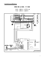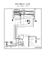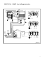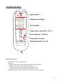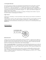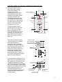
1
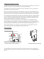
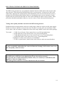
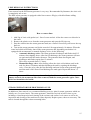
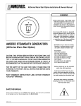
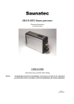
SAUNATEC GROUP Oy
New HELO- HSX M steam generator for home and
professional use.
- Operating instructions
- Installation instructions
Operating and installation instructions for models:
HELO HSX M 34, 47, 60, 77, 95, 120, 140.
7014121
314 SHS 56 D
Technical specifications:
• Voltage: 400V – 415V 3N~ 50Hz (230V – 240V 1N~ 3.4 – 7.7 kW).
• Power alternatives: 3.4kW-14kW.
• Enclosure rating: IP 20.
• Installation mounting: Floor/Wall.
• Water tank material: Aisi 316, acid-resistant steel.
• 2-phase control for thermal resistance. (Not in the special Belgian version)
• Steamer dimensions: 520 x 380 x160 mm
Easy to use:
• Automatic discharge and flush programme.
• Automatic fill and water level control.
• Floor or wall mounting.
• Digital control panel.
- Temperature control
- Time setting
- Light control
• Control panel can be installed inside the steamroom.
• Magnetic valve equipped with a large discharge port, allowing larger contaminants and lime
deposits to be flushed from the tank after each use. (Accessory)
Easy to maintain:
• Replaceable resistors (3 pcs), 1 of which is equipped with a thermal fuse.
• Lime remover (citric acid) fill port is conveniently located on top of the steam generator.
• Components can be easily replaced:
- Circuit board
- Thermal resistors
- Surface level sensor
2
OPERATION AND INSTALLATION:
The HSX M steam generator is only intended for use in the heating of steambaths. Use of the steam
generator in any space other than intended can result in structural damage.
The manufacturer is not liable for any damages caused by installation in a space not intended for
steambath use or misuse of the generator.
Before connecting the steam generator to the mains power, connect all water and steam lines. All
lines must be connected with the greatest care. Ensure that all joints are properly sealed. Although
thread seal tape can be used to properly seal threaded joints, soldering the joints is recommended.
The steam generator should be placed away from water and moisture (dry space). The space should
be well-ventilated, as the steam generator also generates heat. The minimum recommended safety
clearance on each side and above the generator is 30 cm. When placing the steam generator, also
take into consideration the space required for its maintenance.
Ensure that there is a drain in close proximity to the steam generator for discharging the tank.
The steam generator can be mounted on the floor (free standing) or on the wall using mounting
brackets. When using wall brackets, use a fastening method and mounting screws appropriate to the
wall material in question. When filled with water, the steam generator weighs approx. 17 kg.
If the automatic discharge valve is being used, a wall-mounting is recommended to ensure the
proper discharge pressure in the discharge pipe leading into the drain.
HSX M installation
Temperature sensor
Control panel
Water connection
OK
ON
OK
OF F
ON
OF F
400V 3N~
Button
Steam nozzle
Discharge
Location of control panel and button
Steam generator wall mounting
The control panel can be mounted either inside or outside the steamroom. If the control panel is
mounted outside the steamroom, a separate thermostat connected to the circuit board must always
be used.
3
EQUIPMENT CONNECTIONS
16
38
Overpressure
valve
Steam outlet
Water fill
Main switch
Control panel cable
Electrical feed
52
Automatic
magnetic
valve
connector
Water discharge valve
(manual or electrically-operated)
Water and steam line connection
Connect the ¾” flexible water line hose (included in package) from the water connector on the
steam generator installation panel (see figure) to the household cold water line. The water pressure
should be a minimum of 0.2 bar and maximum of 10 bar. The water feed pipe should be fitted with
a manual shutoff valve, which can be used to cut off the flow of water to the generator if it will be
out of use for an extended period of time.
Observe local regulations when installing the steam generator.
The steam line connector should be at least 18x16 mm (generator output: 3.4 kW-9.5 kW) and
22x20 mm (generator output: 12.0 kW- 14.0 kW) copper piping or a similarly sized heat-resistant
silicone hose. The steam line diameter should be consistent for its entire length.
The steam line should go up or down from the steam generator into the steamroom. NO drainage
traps/water pockets may be installed on the line - any water condensation forming in the steam line
must be able to run freely into the steamroom or back into the steam generator. If an odorising
pump has been connected to the steam generator, the line discharge must always run away from the
steam generator, to ensure that the chemicals do not enter the tank.
The maximum recommended steam line length is 5 m.
Additional steam line insulation is always recommneded, both for safety reasons and to prevent
water condensation in the line.
WARNING! Hot steam can cause severe burns.
The manual drain valve supplied with the steam generator is used to empty the steam generator
tank. An electrically-operated magnet valve is available as an accessory.
The steam generator tank should be discharged after each use. This will extend the service life
of the generator and reduce lime deposits.
4
ELECTRICAL CONNECTIONS:
The steam generator is connected (semi-fixed connection) to the mains power, in accordance with
local installation regulations.
Steamer
Power 400V/415V 3N 230V/240V 1N
KW
Amp
Amp
230V3~
Amp
Room size
m³ *)
HSX 34
HSX 47
HSX 60
HSX 77
HSX 95
HSX 120
HSX 140
3.4
4.7
6.0
7.7
9.5
12.0
14.0
8/8
12/11
15/14
19/18
24/23
30/29
35/34
1.5-2.5
2.5-5
5-7
7-10
10-12
12-15
15-18
5/5
7/6,5
9/8
12/11
15/13
19/17
23/21
15/14
20/19
26/25
33/32
Electrical connections are only to be installed by a licensed electrician.
*) Walls made of heavy materials, such as concrete, brick or stone require a higher output to
generate sufficient heat. Ventilation must also be given extra power.
The required power output can be estimated using the fomula below.
Volume (m3) x K1 x K2 = Required output (kW)
Ventilation
No ventilation
Acrylic walls
Light construction wall: drywall + tile
Heavy construction wall: stone, concrete + tile
K1 = 0.75
K1 = 0.52
K2 = 1.00
K2 = 1.25
K2 = 1.50
Steam generator 2-phase control: (Not in the special Belgian version)
The steam generator thermal resistors are 2-phase controlled.
Example: The temperature is set for +43 °C. When the temperature reaches +43 °C two resistors
are switched off with a contactor and one remains on to maintain the temperature with a relay on the
circuit board. If the temperature drops 1 °C, all resistors will be switched back on. If the
temperature rises 1 °C, all three resistors will be shut off. This will ensure an even steam output for
the duration of operation.
5
CONNECTION SCHEMATICS:
HSX M 3,4 kW - 7,7 kW
3 N~ 400 V - 415 V or
1 N~ 230 V - 240 V
Resistors
3 N~
Contactor
6
2
5
1
1 N~
L3
L3
L2
L2
L1
L1
N
N
N
N
Gr
Gr
Thermo fuse
Main
switch
Top cover
PE
Upper limit S2
N
Water valve
discharge
230 V AC
Water valve
fill
230 V AC
L
H1
N
H2
N
V1
N
V2
OLEA 72
LC1 LC2 B1 B2 T1 T2
N
A K S1 S2 TX RX +5 0
Lower limit S1
White
Red
Green
Serieal traffic
MIDI controller
Yellow
Levelprobe
in Tank
White
Yellow
Green
Button
Brown
White
Red
Thermostat
Alarm 12 V DC
Light control opto. max 24 V DC, 50 mA
354 SHS 30 A
6
HSX MIDI 9,5 - 14 kW
3 N~ 400 V - 415 V
Resistors
3 N~
Contactor
6
5
L3
L2
2
1
L1
N
Thermo fuse
N
Gr
Main
switch
Top cover
PE
Upper limit S2
Water valve
discharge
230 V AC
Water valve
fill
230 V AC
L
N
H1
N
H2
N
V1
N
V2
OLEA 72
A K S1 S2 TX RX +5 0
N
White
LC1 LC2 B1 B2 T1 T2
Lower limit S1
White
Red
Green
Serieal traffic
MIDI controller
Yellow
Levelprobe
in Tank
White
Yellow
Green
Button
Brown
Red
Thermostat
Alarm 12 V DC
Light control opto. max 24 V DC, 50 mA
354 SHS 31 A
7
HSX-M 3,4 - 14 kW Special Belgian version
6
5
4
3
Contactor
6
Resistor
5
K2
2
1
6
5
4
3
2
K11
3,4 - 7,7 kW 230 V 1N~ / 2~
4
3
1
2
3
4
6
5
2
L2
L1 / N
Thermofuse 167 C
1
Main
switch
3,4 - 14 kW 230 V 3~
Top cover
1
2
3
4
5
6
L2 L3
L1
OLEA 72
PE
3,4 - 14 kW 400 V 3N~
High level S2
Low level S1
N
L
N
H1
N
H2
N
V1
N
V2
OLEA 72
LC1 LC2 B1 B2 T1 T2 A K S1 S2 TX RX +5 0
Water
valve
drain
230V AC
Watervalve
filling
230V AC
White
Red
Green
Yellow
Control
keyboard
White
Yellow
Green
Brown
On / Off pushbutton
White
Red
Level probe
1
2
3
4
5
6
Thermostat
Alarm 12 V DC
Light control opto max. 24 V DC, 50 mA
N
L1 L2 L3
354 SHS
8
TEAM GENERATOR AND AUXILIARY PARTS INSTALLATION:
Temperature sensor
Control panel
Water connection
OK
ON
OFF
OK
ON
OFF
400V 3N~
Buttom
Steam nozzle
Discharge
The control panel can also be installed inside the steamroom. If the control panel is installed
outside the steamroom or so low that its own thermostat will not display the proper temperature, a
separate thermostat must be used, which is connected directly to the circuit board and installed 170
cm above floor level, preferably on the wall opposite the steamroom door.
The push button can be fitted either in the steam room or outside of it. In addition it is also
recommended to install a limiting thermostat to prevent the rise of the temperature above +50 °C
when the steam room is used for longer than 30 minutes, which is the fixed operating time of a
steamer equipped with a push button. See the separate installation and connection picture.
The steam nozzle(s) are installed approx. 20 – 40 cm above floor level under the bench or seat, or
on the wall, making sure that the hot steam does not burn your feet. When placing the nozzles, also
make sure that they will not be touched accidently. The steam temperature is + 100 °C and can
cause severe burns.
The thermostat is installed at a height of 170 cm, preferably on the wall opposite the door.
The installation space for the thermostat should also be sealed with a suitable material to prevent the
seeping of moisture into the structure. The thermostat is connected directly to the steamer circuit
card and its program will automatically incorporate it, see the connection picture.
9
CONTROL PANEL HSX M
Light control
Temperature display
Time display
Temperature control 25 - 50 °C
OK
Time setting (0 - 4 hours)
Temperature sensor
ON
OFF
Steam generator on / off
Digital control panel
-ON/OFF button for steam generator
-OK button
- Bathing temperature selector button (temperature display flashes)
- Bathing time selector button (time display flashes)
+ button increases both time setting and temperature value
- button decreases both time setting and temperature value
-Light control button, opto switch max. 24 V DC, 50 mA, (normal open)
10
Control panel function:
The steam generator is turned on by pressing the ON-OFF button on the control panel. After this,
the temperature display will begin to flash. The temperature can be set to the degree (ranging
between 25 °C – 50 °C) by pressing the + or – buttons. If the temperature value on the display is
correct, press the OK button and move on to the time display. While the display is flashing, you can
set the time to the minute (up to 90 minutes) using the + or – buttons, after which the display will
change to hours (max. 4 hours).
When the time remaining reaches 90 minutes, the display will change back to minutes. Any time
beyond 90 minutes is only displayed in full hours.
Light control:
Lights can be controlled by a control panel button, which, when pressed, will activate an LED next
to the button.
Connectors LC1 and LC2 on the circuit board are for light control. The circuit board draws external
voltage (24V DC max. 50mA), which is switched to connector LC1. When the light button is
pressed, the circuit board transistor will transfer power to connector LC2, which controls the actual
lighting unit.
BUTTON HSX M
Led indicator light
ON - OFF button
Button function:
Turning on the steam generator with the button will take 30 minutes, at which time the LED above
the button will come on. The steam generator time cannot be set – it will shut itself off. The steam
generator can also be shut off before time runs out by pressing the button, at which time the LED
will turn off. If desired, the steam generator can be turned on again.
.
When using the push button it is recommended to install the limiting thermostat to prevent the rise
of the temperature above +50 °C when the steam room is used for longer than 30 minutes, which is
the fixed operating time of a steamer equipped with a push button. See the separate installation and
connection picture.
The 2-phase control works with the button control version by switching off two thermal resistors
with a contactor when the thermostat measures a temperature of +50 °C. When the temperature
drops 1 °C, all three resistors are switched back on. If the temperature rises above +50 °C, all three
resistors will be switched off.
11
CONTROL PANEL, BUTTON AND THERMOSTAT INSTALLATION:
The control panel is filled
with mass, which makes
it moisture-resistant. The
control panel can be
installed directly in the wall.
The installation hole in the
steamroom should be sealed
to prevent moisture from
travelling along the line, thus
concealing the cable behind
the control panel. Alternatively,
the cable can be run from the
bottom of the control panel
through a pre-cut hole.
The control panel frame is
pressed directly on top of the
unit. To remove the frame,
use the included tool. The
frame has small holes around
its edges. (4) Using the tool,
lightly press the locking pin in
each hole and then pull the
frame out.
The button is filled with mass,
which allows it to be installed
inside the steamroom.
The button can be installed
through the wall (acrylic walls)
or by drilling a suitable hole, into
which the button can be set,
making sure that its edges are
sealed with a suitable caulk.
If necessary, surface-mount
boxes can be used. These do
not require sealing as the button
itself is moisture-resistant.
55 mm
Mounting hole
5 mm
Locking
Locking
Holes interval
180 mm
150 mm
OK
Locking
Locking
ON
OFF
Led indicator light
ON - OFF button
40 mm
Back nut
32 mm
46 mm
24 mm
The thermostat is installed 170 cm
above floor level, preferably on the
wall opposite the steamroom door.
If required, the back nut can be
used when working with a plexiglas
wall. On thicker walls, a hole can be
drilled out and sealed with a suitable
caulk to prevent moisture from
reaching building structures.
The thermostat is inserted into its
casing and then fastened with
locking screws.
Wall
Locking screw
24 mm
32 mm
21 mm
Thermostat
Thermostat
casing
Locking screw
12
DISCHARGING AND FLUSHING:
A separate electrically-operated valve with a separate automatic drain and rinsing operation is
available for the steamer (Accessory). The electrically-operated drain valve opens once 15 minutes
has passed since the steamer shuts down.
This function is available in both control panel and button operation versions.
In the button version the LED will flash in one-second intervals during the 15-minute discharge and
flushing wait period after the steam generator has shut off.
After the tank has been discharged, the steam generator will wait for the next start command.
DISCHARGE VALVE :
Installation of the HSX steam generator:
- Use the duct tape included (as a minimum) to seal the electrically-operated valve threads.
- Connect the included electrically-operated valve power cord to the power mains.
- Run a discharge pipe from the discharge valve into a drain. NOTE! Because water will run at its
own pressure, the steam generator
should be installed some distance away from the drain.
ALARMS:
Control panel
E1 When switching on or with the steam generator already running, the water faucet is shut or
water is for some other reason being prevented from flowing into the steam generator. Turn on the
water faucet. If the fault is in the steam generator, it may require servicing.
E2 The fault alarm will be given when the serial traffic between the control panel and circuit board
malfunctions.
Requires service to find the cause of the fault.
When the fault alarm is given, the steam generator will shut down. Repair the cause of the fault or
call an authorised service technician. Malfunctions can be reset by pressing the ON/OFF button.
In button-equipped versions the button LED will flash rapidly when the fault is detected; the steam
generator is running when the water faucet is shut or for some other reason water is being prevented
from flowing into the steam generator. This alarm is also given when the water feed is cut while the
steam generator is running. The malfunction can be reset by pressing the button. Repair or replace
the cause of the fault.
The circuit board output for an external alarm is 12 V DC max 50 mA. The output is activated when
alarm E1 or E2 is displayed or the LED flashed rapidly. The alarm is reset by pressing the ON/OFF
button.
13
HSX STEAM GENERATOR SERVICING PROCEDURES:
The HSX steam generator has a programmed automatic function which drains and rinses the tank
after each use. (The electrically-operated drain valve is an accessory.) A long service life is also
achieved by emptying the steam generator tank immediately after use in areas where the water is
perhaps not of the best possible quality. However, draining the tank is not an alternative for the
regular removal of lime from the tank. It is also worth cleaning the surface sensor at times. These
procedures should be undertaken either by a service centre or some other professional person.
Testing water quality and lime removal for the HSX steam generator
Included with the steam generator test kit are testing strips, which are used to test the water supply
hardness as follows: dip the test strip in the water for about 1 second, pull it out and shake off the
excess water. After one minute, compare the colour of the strip with the colour code on the package.
Test result: < 3° dH, Very soft water, Lime removal once every 500 operating hours.
> 4° dH, Soft water, Lime removal once every 100 operating hours.
> 7° dH, Moderately hard water, Lime removal once every 50 operating hours.
> 14°dH, Hard water, Lime removal once every 30 operating hours,
installation of a lime removal device recommended.
> 21°dH, very hard water, Install a lime removal device and retest water hardness.
These maintenance intervals are the maximum times as recommended by the manufacturer.
It can be worthwhile undertaking the removal of lime and cleaning of the surface sensor even
more frequently, when necessary.
Warranty for the equipment is void, if the steamgenerator has been installed or it has been
used differently to what has been stipulated in the (use instructions) manual.
The warranty also excludes functional problems, if they are caused by so called hard (with
high dH) or otherwise impure water.
The steam generator must be serviced as instructed in the user manual.
14
LIME REMOVAL INSTRUCTIONS:
Lime removal on the HSX steam generator is very easy. Recommended by Saunatec, the citric acid
is completely safe to use.
The HSX steam generator is equipped with a lime remover fill pipe, which facilitates adding
remover to the water tank.
How to remove lime:
1. Add 50g of citric acid (packet) to 1 litre of water and stir. Allow the remover to dissolve in
the water.
2. Remove the plastic cover from the steam generator and open the fill pipe cap.
3. Pour the solution into the steam generator tank (use a funnel if necessary) and screw the cap
back on.
4. Turn on the steam generator and let the water boil for approximately 10 minutes. When the
water has boiled sufficiently, shut off the steam generator and, depending on whether it is
equipped with an automatic or manual discharge valve, do the following:
• Automatic discharge valve: The steam generator discharges and flushes itself 15
minutes after shutting down. After the first discharge, the steam generator will turn
on again and refill the tank with water. The generator shuts down again, and
discharges and flushes again after 15 minutes.
This can be repeated about 3-5 times.
• Manual discharge valve: After boiling, allow the citric acid solution work in the
tank for about 15 minutes and then discharge the tank by opening the discharge
valve. Close the valve after the first discharge and turn on the steam generator again
until the tank is full. Shut off and discharge the tank again. Repeat this about 3-5
times.
The steam generator will be ready to use immediately after lime removal. If you detect a
lemony aroma in the steamroom after lime removal, flush the steam generator again. Citric
acid is not harmful to the health.
STEAM GENERATOR FOR PROFESSIONAL USE:
In addition to lime removal, we recommend drafting a service plan for steam generators which are
in daily use (5 or more hours). The steam generator should be serviced at least 2 times a year,
including a visual inspection and cleaning of the resistors and surface level sensor as well as an
inspection and cleaning of the tank interior (lime deposits). Replace parts, wherever necessary. The
tank is cleaned through the resistor mounting holes.
15