1
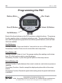
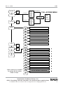
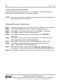
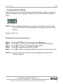
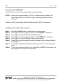
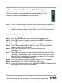
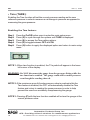
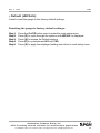
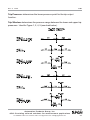
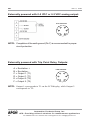
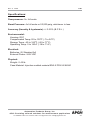
AUTOMATION
P R O D U C T S
G R O U P,
I N C.
Operator’s Manual
PG-7
Full Access
DOC. 9003312
Rev A 12/09
Automation Products Group, Inc.
APG...Providing tailored solutions for measurement applications
Tel: 1/888/525-7300 • Fax: 1/435/753-7490 • www.apgsensors.com • E-mail: sales@apgsensors.com
PG7
Rev. A, 12/09
Table of Contents
Warranty ................................................................................ 3
Programming the PG7 ....................................................... 4-23
Menu Flow Chart ................................................................ 5
Mode Setting ..................................................................... 6
Accessing/Exiting the Setup Menu .................................... 7
Maximum/Minimum Function ........................................... 8
Units of Measure ............................................................... 9
Using Custom Units ................................................... 10
Peak-Hold Feature .......................................................... 11
Advanced Settings ...................................................... 12-17
Auto-Off ...................................................................... 12
Decimal Place ............................................................ 13
Sample Rate .............................................................. 14
Bar Graph ................................................................... 15
Range Adjustment ...................................................... 16
Quick Calibration ........................................................ 17
Tare Feature .................................................................... 18
Default ............................................................................. 19
Outputs ....................................................................... 20-24
Analog Outputs ....................................................... 20-21
Trip Point Outputs ................................................... 22-24
Wiring ............................................................................ 25-26
Specifications ................................................................ 27-28
Automation Products Group, Inc.
APG...Providing tailored solutions for measurement applications
2
Tel: 1/888/525-7300 • Fax: 1/435/753-7490 • www.apgsensors.com • sales@apgsensors.com
Rev. A, 12/09
PG7
• Warranty and Warranty Restrictions
APG warrants its products to be free from defects of material and workmanship
and will, without charge, replace or repair any equipment found defective upon
inspection at its factory, provided the equipment has been returned,
transportation prepaid, within 18 months from date of shipment from factory.
THE FOREGOING WARRANTY IS IN LIEU OF AND EXCLUDES ALL OTHER
WARRANTIES NOT EXPRESSLY SET FORTH HEREIN, WHETHER
EXPRESSED OR IMPLIED BY OPERATION OF LAW OR OTHERWISE
INCLUDING BUT NOT LIMITED TO ANY IMPLIED WARRANTIES OF
MERCHANTABILITY OR FITNESS FOR A PARTICULAR PURPOSE.
No representation or warranty, express or implied, made by any sales
representative, distributor, or other agent or representative of APG which is not
specifically set forth herein shall be binding upon APG. APG shall not be liable
for any incidental or consequential damages, losses or expenses directly or
indirectly arising from the sale, handling, improper application or use of the
goods or from any other cause relating thereto and APG’s liability hereunder, in
any case, is expressly limited to the repair or replacement (at APG’s option) of
goods.
Warranty is specifically at the factory. Any on site service will be provided at
the sole expense of the Purchaser at standard field service rates.
All associated equipment must be protected by properly rated electronic/
electrical protection devices. APG shall not be liable for any damage due to
improper engineering or installation by the purchaser or third parties. Proper
installation, operation and maintenance of the product becomes the
responsibility of the user upon receipt of the product.
Returns and allowances must be authorized by APG in advance. APG will
assign a Return Material Authorization (RMA) number which must appear on
all related papers and the outside of the shipping carton. All returns are subject
to the final review by APG. Returns are subject to restocking charges as
determined by APG’s “Credit Return Policy”.
Automation Products Group, Inc.
APG...Providing tailored solutions for measurement applications
Tel: 1/888/525-7300 • Fax: 1/435/753-7490 • www.apgsensors.com • sales@apgsensors.com
3
PG7
Rev. A, 12/09
Programming the PG7
Battery Meter
Bar Graph
Zero (Z) Button
Select (S) Button
On/Off Button
Each of the three buttons on the PG7 performs multiple functions. The primary
function applies when in standard operating mode. The secondary functions
are used for programming operations and when special features, such as PeakHold, are enabled.
On/Off Button
Primary Function: Press and hold for 1 second to turn on or off the gauge.
Secondary Function: Press once to access the main setup menu.
Zero Button (Z)
Primary Function: Press to “zero” the gauge reading (the reading must be less
than 5% of full-scale in order to zero the gauge).
Secondary Function: Cycles through the options in the setup menus.
Select Button (S)
Primary Function: Cycles between the current, maximum, and minimum pressure
readings.
Secondary Function: Used to accept the displayed option while in the setup
menus.
Secondary Function: Resets the peak-hold reading when the peak-hold feature
is enabled.
Automation Products Group, Inc.
APG...Providing tailored solutions for measurement applications
4
Tel: 1/888/525-7300 • Fax: 1/435/753-7490 • www.apgsensors.com • sales@apgsensors.com
Rev. A, 12/09
MAXMIN
PG7
YES
NO
<= 120 psi
UNITS
P HOLD
ON
OFF
ADVSET
TARE
ON
OFF
DEFAULT
YES
NO
> 120 psi
PSI
BAR
KPA
CUSTOM
MBAR
INHG
INH20
MMHG
PSI
BAR
KPA
CUSTOM
KGCM^2
MPA
FTH20
CMHG
CUSTOM ONLY
FULL ACCESS MENU
SELECT
MULTIPLIER
LBF
KN
LBS
KG
NEWTON
CUSTOM ONLY
AUTO
OFF, 2 MIN, 4 MIN, 8 MIN, 16 MIN, 32 MIN
DEC PL
HI RES, MEd Res, LO RES
SAMPLE
SLOW, MEDIUM, FAST
BAR 0
SET BAR GRAPH 0%
BAR100
SET BAR GRAPH 100%
RANGE
SET RANGE (LBS ONLY)
CALIBR
FAST CALIBRATE, ZERO AND SPAN
EXIT
AL SET
SET ANALOG LOW SET PRESSURE
AH SET
SET ANALOG HIGH SET PRESSURE
AL CAL
SET ANALOG LOW CALIBRATION
AH CAL
SET ANALOG HIGH CALIBRATION
T1TYPE
TYPE0, TYPE1, TYPE2, TYPE3, TYPE4, TYPE5
T1PRES
SET TRIP PRESSURE 1 START PRESSURE
T1WIN
SET TRIP PRESSURE 1 WINDOW SIZE
T2TYPE
TYPE0, TYPE1, TYPE2, TYPE3, TYPE4, TYPE5
T2PRES
SET TRIP PRESSURE 2 START PRESSURE
T2 WIN
SET TRIP PRESSURE 2 WINDOW SIZE
OUTPUT
EXIT
* Menu options only available
for gauges with an analog
output or relays.
EXIT
Automation Products Group, Inc.
APG...Providing tailored solutions for measurement applications
Tel: 1/888/525-7300 • Fax: 1/435/753-7490 • www.apgsensors.com • sales@apgsensors.com
5
PG7
Rev. A, 12/09
Accessing the Mode Setting:
Step 1: Simultaneously press and hold the On/Off button and the (S) button
for approximately 3 seconds. This will bring up the 3 digit mode
number.
Step 2: Enter the desired mode number (see mode definitions below)
by using (Z) to change the value of the flashing digit, and (S) to
advance to the next digit.
Mode Definitions:
Mode 000: Full Access
- Provides access to all menu settings. If no buttons are pushed for 1
minute, the gauge will revert back to Mode 003 (factory default).
Mode 002: Limited Access
- Menu is locked
- (Z) button zeros the reading
- (S) cycles between the Max and Min readings
- On/Off functions only on battery powered gauges
Mode 003: Factory Default
- Full access except Full Scale Calibration is locked
Mode 005: Locked Access
- All buttons locked except the on/off button on battery powered
gauges.
Automation Products Group, Inc.
APG...Providing tailored solutions for measurement applications
6
Tel: 1/888/525-7300 • Fax: 1/435/753-7490 • www.apgsensors.com • sales@apgsensors.com
Rev. A, 12/09
PG7
Zero (Z) Button
Select (S) Button
On/Off Button
Accessing the Full Setup Menu:
Step 1: Simultaneously press and hold the On/Off button and the (S) button
for approximately 3 seconds. This will bring up the 3 digit mode
number.
Step 2: Using (Z) to change the value of the flashing digit, and (S) to advance
to the next digit, change the mode number to 000.
Step 3: Press On/Off to enter the setup menu, and press (Z) to scroll through
menu choices.
Exiting the Main Setup Menu:
Step 1:
Step 2:
Step 3:
Step 4:
While in the main setup menu, press (Z) until EXIT is displayed.
Press (S) to access the Exit options.
Press (Z) until YES is displayed.
Press (S) to Exit the main setup menu and return to the standard
operating mode.
Automation Products Group, Inc.
APG...Providing tailored solutions for measurement applications
Tel: 1/888/525-7300 • Fax: 1/435/753-7490 • www.apgsensors.com • sales@apgsensors.com
7
PG7
Rev. A, 12/09
• Maximum/Minimum Reset (MAXMIN):
Pressing the (S) button while in standard operating mode will cycle between
displaying the current pressure reading, the Maximum pressure reading and the
Minimum pressure reading. The maximum and minimum readings will be stored
until the gauge is powered down or the max/min readings are reset.
Resetting the Max/Min readings:
Step 1:
Step 2:
Step 3:
Step 4:
Step 5:
Press the On/Off button once to enter the main setup menu.
Press (Z) to cycle through the options until MAXMIN is displayed.
Press (S) to access the Max/Min reset options.
Press (Z) to toggle between YES and NO until YES is displayed.
Press (S) to reset the Max/Min readings and return to the main setup
menu.
Automation Products Group, Inc.
APG...Providing tailored solutions for measurement applications
8
Tel: 1/888/525-7300 • Fax: 1/435/753-7490 • www.apgsensors.com • sales@apgsensors.com
Rev. A, 12/09
PG7
• Units of Measure (UNITS):
Allows the user to select the unit of measure to be displayed as the pressure
reading.
Options:
For gauges over 120 psi:
PSI
(pounds per square inch)
bAR
(bar)
KPA
(kilopascals)
*CUSTOM
(see “Using Custom Units” on next page)
KGCM^2
(kilograms per cubic centimeter)
MPA
(megapascals)
FTH20
(feet of water @ 60 F)
cmHG
(centimeters of mercury)
For gauges less than 120 psi:
PSI
(pounds per square inch)
bAR
(bar)
KPA
(kilopascals)
*CUSTOM
(see “Using Custom Units” on next page)
mbAR
(millibar)
INHG
(inches of mercury)
INH20
(inches of water @ 60 F)
mmHG
(millimeters of mercury)
Setting the Unit of Measure:
Step 1:
Step 2:
Step 3:
Step 4:
Press the On/Off button once to enter the main setup menu.
Press (Z) to cycle through the options until UNITS is displayed.
Press (S) to access the Units options.
Press (Z) to cycle through setting options until the desired unit of
measure is displayed.
Step 5: Press (S) to apply the setting and return to the main setup menu.
Automation Products Group, Inc.
APG...Providing tailored solutions for measurement applications
Tel: 1/888/525-7300 • Fax: 1/435/753-7490 • www.apgsensors.com • sales@apgsensors.com
9
PG7
Rev. A, 12/09
Using Custom Units (CUSTOM):
The Custom Units setting allows the user to display a volumetric weight by
applying a conversion factor to the pressure reading.
NOTE: The conversion factor must be calculated using Pound per Square Inch
(psi) as the base unit of measure.
Setting the Custom Units feature:
Step 1:
Step 2:
Step 3:
Step 4:
Step 5:
Step 6:
Step 7:
Step 8:
Step 9:
Step 10:
Calculate the conversion factor from psi to the desired unit of measure.
Press the On/Off button once to enter the main setup menu.
Press (Z) to cycle through the options until UNITS is displayed.
Press (S) to access the Units setting options.
Press (Z) to cycle through the Units options until CUSTOM is
displayed.
Press (S) to access the Custom Units setting. A 5-digit conversion
factor will appear with the first digit flashing.
Press (Z) to change the value of the flashing digit (options: 0-9).
Press (S) to accept the flashing digit and advance to the next
digit......repeat steps 7 and 8 as necessary.
After the last digit is accepted by pressing (S), use (Z) to scroll
through the custom units of measure; LBF, KN, LBS, KG, NEWTON.
Press (S) to accept the custom unit and return to the main setup menu.
Automation Products Group, Inc.
APG...Providing tailored solutions for measurement applications
10
Tel: 1/888/525-7300 • Fax: 1/435/753-7490 • www.apgsensors.com • sales@apgsensors.com
Rev. A, 12/09
PG7
• Peak-Hold (P HOLd):
When the Peak-Hold is enabled, the gauge will display the “peak” or maximum
pressure reading since the gauge was powered on or the Max/Min value was
reset.
NOTE 1: When the Peak-Hold feature is enabled, a small box containing the
words PEAK HOLD will be displayed in the upper left corner of the
display.
Options: Off or On
Enabling the Peak-Hold feature:
Step 1:
Step 2:
Step 3:
Step 4:
Step 5:
Press the On/Off button to enter the main setup menu.
Press (Z) to cycle through the options until P HOLd is displayed.
Press (S) to access the Peak-Hold setting options.
Press (Z) to toggle between OFF and ON.
Press (S) to apply the displayed setting and return to main setup menu.
NOTE 2: The peak value can be reset by pressing (S) with the Peak-Hold
function enabled.
Automation Products Group, Inc.
APG...Providing tailored solutions for measurement applications
Tel: 1/888/525-7300 • Fax: 1/435/753-7490 • www.apgsensors.com • sales@apgsensors.com
11
PG7
Rev. A, 12/09
• Advanced Settings (AdVSET):
The Advanced Settings menu is used to customize the LCD display and to
setup any optional features, such as an analog output.
Auto-Off (AUTO):
This function is applicable to battery powered units only. The Auto-Off feature
allows the user to designate the time of inactivity (no buttons pushed) until the
gauge automatically powers down.
Options: 2 MIN, 4 MIN, 8 MIN, 16 MIN, 32 MIN and OFF
NOTE: Selecting OFF disables the Auto-Off feature; the gauge will then remain
powered indefinitely as long as there is sufficient voltage being
supplied (~1.8V).
Setting the Auto-Off feature:
Step 1: Press the On/Off button to enter the main setup menu.
Step 2: Press (Z) to cycle through the menu options until AdVSET is
displayed.
Step 3: Press (S) to enter the Advanced Settings menu.
Step 4: Press (Z) to cycle through the menu options until AUTO is displayed.
Step 5: Press (S) to access the Auto-Off setting options.
Step 6: Press (Z) to cycle through setting options until the desired setting is
displayed.
Step 7: Press (S) to apply the setting and return to advanced setup menu.
Step 8: To exit the advanced setup menu, press (Z) until EXIT is displayed and
press (S) to exit to the main setup menu.
Automation Products Group, Inc.
APG...Providing tailored solutions for measurement applications
12
Tel: 1/888/525-7300 • Fax: 1/435/753-7490 • www.apgsensors.com • sales@apgsensors.com
Rev. A, 12/09
PG7
Decimal Place (dEC PL):
The reading can be set to display in High Resolution (HI RES), Medium
Resolution (MEdRES) or Low Resolution (LO RES) mode. Switching between
resolutions will shift the displayed reading by one decimal place position.
NOTE: Gauges without a decimal place position will display a dummy zero (or
zeros) when the resolution is changed to medium or low.
Options: HI RES (high resolution), MEdRES (medium resolution) or LO RES
(low resolution)
Setting the Decimal Place feature:
Step 1:
Step 2:
Step 3:
Step 4:
Step 5:
Step 6:
Step 7:
Press the On/Off button to enter the main setup menu.
Press (Z) to cycle through the options until AdVSET is displayed.
Press (S) to enter the Advanced Settings menu.
Press (Z) to cycle through the options until dEC PL is displayed.
Press (S) to access the Decimal Place setting options.
Press (Z) to cycle through the resolution settings.
Press (S) to apply the displayed setting and return to advanced setup
menu.
Step 8: To exit the advanced setup menu, press (Z) until EXIT is displayed and
press (S) to exit to the main setup menu.
Automation Products Group, Inc.
APG...Providing tailored solutions for measurement applications
Tel: 1/888/525-7300 • Fax: 1/435/753-7490 • www.apgsensors.com • sales@apgsensors.com
13
PG7
Rev. A, 12/09
Sample Rate (SAMPLE):
Adjusts the rate at which the gauge takes sample readings.
NOTE: Setting the Sample Rate to “SLOW” will help preserve battery life
(when applicable) and will also help to smooth rapidly fluctuating
readings.
Options: SLOW (4x/second), MEdIUM (8x/second), FAST (16x/second)
Setting the Sample Rate feature:
Step 1:
Step 2:
Step 3:
Step 4:
Step 5:
Step 6:
Press the On/Off button to enter the main setup menu.
Press (Z) to cycle through the options until AdVSET is displayed.
Press (S) to access the Advanced Settings menu.
Press (Z) to cycle through the options until SAMPLE is displayed.
Press (S) to access the Sample Rate setting options.
Press (Z) to cycle through the setting options until the desired setting
is displayed.
Step 7: Press (S) to apply the displayed setting and return to advanced setup
menu.
Step 8: To exit the advanced setup menu, press (Z) until EXIT is displayed and
press (S) to exit to the main setup menu.
Automation Products Group, Inc.
APG...Providing tailored solutions for measurement applications
14
Tel: 1/888/525-7300 • Fax: 1/435/753-7490 • www.apgsensors.com • sales@apgsensors.com
Rev. A, 12/09
PG7
Bar Graph 0% (bAR 0) & Bar Graph 100% (bAR100) Settings:
Allows the user to define the reading values associated with 0% and
100% on the display bar graph. Bars will appear/disappear in 10%
increments of the total span between the two values.
NOTE: The 0% reference does not have to be the lower pressure setting; 0%
can be set as the higher pressure setting, thereby causing the bar
graph to increase as the pressure decreases. Negative pressure
settings can also be used as either the 0% or 100% reference points.
Setting the Display Bar Graph:
Step 1:
Step 2:
Step 3:
Step 4:
Step 5:
Step 6:
Step 7:
Step 8:
Step 9:
Step 10:
Press the On/Off button once to enter the main setup menu.
Press (Z) to cycle through the options until AdVSET is displayed.
Press (S) to access the Advanced Settings menu.
Press (Z) to cycle through the options until BAR 0 is displayed.
Press (S) to access the Bar Graph 0% value. A 5-digit number will
appear with the first digit flashing.
Press (Z) to change the value of the first flashing digit
(options: 0-9 or “-”).
Press (S) to accept the value of the flashing digit and advance to the
next digit......repeat steps 6 and 7 until the desired 0% reading is fully
entered. After the last digit is accepted by pressing (S), the display
will return to the advanced setup menu.
Press (Z) to cycle through the options until BAR100 is displayed.
Repeat Steps 5-7 to enter the Bar Graph 100% value.
To exit the advanced setup menu, press (Z) until EXIT is displayed and
press (S) to exit to the main setup menu.
Automation Products Group, Inc.
APG...Providing tailored solutions for measurement applications
Tel: 1/888/525-7300 • Fax: 1/435/753-7490 • www.apgsensors.com • sales@apgsensors.com
15
PG7
Rev. A, 12/09
Full-Scale Range Adjust (RANGE):
Allows the user to adjust the reading at full-scale pressure. The reading can be
adjusted by +/-10% full-scale.
NOTE: The pressure reading must be within 5% of the full-scale value in order
to make Range adjustments. For example, a 1000 psi gauge would need
to be reading between 950 psi and 1050 psi in order to adjust the Range
feature. If the reading is not within 5% of full scale, NOAdJU (No
Adjustment) will be displayed when trying to adjust the Range.
Adjusting the Full-Scale Range:
Step 1:
Step 2:
Step 3:
Step 4:
Step 5:
Step 6:
Step 7:
Step 8:
Ensure that the pressure reading is within 5% of full-scale.
Press the On/Off button to enter the main setup menu.
Press (Z) to cycle through the options until AdVSET is displayed.
Press (S) to access the Advanced Settings menu.
Press (Z) to cycle through the options until RANGE is displayed.
Press (S) to enter the Range adjust mode.
Press (Z) to increase the reading, or press (S) to decrease the reading.
Press the On/Off button to accept the adjusted reading and return to
the advanced setup menu.
Step 9: To exit the advanced setup menu, press (Z) until EXIT is displayed and
press (S) to exit to the main setup menu.
Automation Products Group, Inc.
APG...Providing tailored solutions for measurement applications
16
Tel: 1/888/525-7300 • Fax: 1/435/753-7490 • www.apgsensors.com • sales@apgsensors.com
Rev. A, 12/09
PG7
Quick Calibration (CALIBR):
Allows the user to perform a quick calibration of the zero and span.
NOTE: Both zero pressure and full-scale pressure must be applied to the
gauge in order to complete the quick calibration process.
Step 1: Press the On/Off button to enter the main setup menu.
Step 2: Press (Z) to cycle through the menu options until AdVSET is
displayed.
Step 3: Press (S) to enter the Advanced Settings menu.
Step 4: Press (Z) to cycle through the options until CALIBR is displayed.
Step 5: Press (S) to access the CALIBR mode. The gauge will display the
word ZERO, prompting the user to perform the zero pressure quick
calibration.
Step 6: Ensure no pressure is applied to the gauge. Press (Z) to zero the gauge.
The gauge will then display the word SPAN, prompting the user to
perform the full-scale pressure quick calibration.
Step 7: Apply full jack pressure to the gauge and press the (S) button to
complete the quick calibration and return to advanced setup menu.
Step 9: To exit the advanced setup menu, press (Z) until EXIT is displayed and
press (S) to exit to the main setup menu.
Automation Products Group, Inc.
APG...Providing tailored solutions for measurement applications
Tel: 1/888/525-7300 • Fax: 1/435/753-7490 • www.apgsensors.com • sales@apgsensors.com
17
PG7
Rev. A, 12/09
• Tare (TARE):
Enabling the Tare function will set the current pressure reading as the zero
reference pressure in order to measure a net change in pressure as opposed to
measuring the gross pressure.
Enabling the Tare feature:
Step 1:
Step 2:
Step 3:
Step 4:
Step 5:
Press the On/Off button once to enter the main setup menu.
Press (Z) to cycle through the options until TARE is displayed.
Press (S) to access the Tare setting options.
Press (Z) to toggle between OFF and ON.
Press (S) button to apply the displayed option and return to main setup
menu.
NOTE 1: When tare function is enabled, the T5 symbol will appear in the lower
left corner of the display.
WARNING: Do NOT disconnect the gauge from the pressure fitting while the
tare function is enabled. The gauge could still be under pressure
even though the reading shows 0.
NOTE 2: If the maximum gross full-scale pressure value is reached while the
Tare feature is enabled, the PG7 will automatically disable the Tare
feature and return to reading the gross pressure in order to help
prevent the user from accidently overpressuring the gauge.
NOTE 3: Pressing (Z) with the tare function enabled will re-tare the gauge at the
current pressure value.
Automation Products Group, Inc.
APG...Providing tailored solutions for measurement applications
18
Tel: 1/888/525-7300 • Fax: 1/435/753-7490 • www.apgsensors.com • sales@apgsensors.com
Rev. A, 12/09
PG7
• Default (dEFAUL):
Used to reset the gauge to the factory default settings.
Resetting the gauge to factory default settings:
Step 1:
Step 2:
Step 3:
Step 4:
Step 5:
Press the On/Off button once to enter the main setup menu.
Press (Z) to cycle through the options until dEFAUL is displayed.
Press (S) to access the Default options.
Press (Z) to cycle between NO and YES.
Press (S) to apply the displayed setting and return to main setup menu.
Automation Products Group, Inc.
APG...Providing tailored solutions for measurement applications
Tel: 1/888/525-7300 • Fax: 1/435/753-7490 • www.apgsensors.com • sales@apgsensors.com
19
PG7
Rev. A, 12/09
• OUTPUT:
Used to configure any optional gauges outputs, such as an analog signal or trip
point relays.
Analog Low (AL SET) & Analog High (AH SET) Setpoints:
Allows the user to define the reading values associated with the Low Analog
signal (i.e. 4mA or 0V) and the High Analog signal (i.e. 20mA, 2V or 5V).
NOTE: The analog setpoints must be entered using the gauge’s base unit of
measure (typically PSI).
Setting the Analog Signal Span:
Step 1:
Step 2:
Step 3:
Step 4:
Step 5:
Step 6:
Step 7:
Step 8:
Step 9:
Step 10:
Step 11:
Press the On/Off button once to enter the main setup menu.
Press (Z) to cycle through the options until OUTPUT is displayed.
Press (S) to access the Output Settings menu.
Press (Z) to cycle through the options until AL SET is displayed.
Press (S) to access the Analog Low setpoint value. A 5-digit number
will appear with the first digit flashing.
Press (Z) to change the value of the first flashing digit
(options: 0-9 or “-”).
Press (S) to accept the value of the flashing digit and advance to the
next digit......repeat steps 6 and 7 until the desired Analog Low reading
is fully entered. After the last digit is accepted by pressing (S), the
display will return to the main options menu.
Press (S) to reenter the Output Settings menu.
Press (Z) to cycle through the options until AH SET is displayed.
Repeat Steps 5-7 to enter the Analog High setpoint value.
To exit the output menu, press (Z) until EXIT is displayed and press
(S) to exit to the main setup menu.
Automation Products Group, Inc.
APG...Providing tailored solutions for measurement applications
20
Tel: 1/888/525-7300 • Fax: 1/435/753-7490 • www.apgsensors.com • sales@apgsensors.com
Rev. A, 12/09
PG7
Analog Low (AL CAL) & Analog High (AH CAL) Calibration:
Allows the user to calibrate or “trim” the endpoints of the analog signal output
(i.e. 4mA & 20mA or 0V & 2V/5V)
Calibrating the Analog Signal End-Points:
Step 1: Use a calibrated meter to monitor the analog output signal.
Step 2: Force a low analog output signal (i.e. 4mA or 0V) either by adjusting
the applied pressure or by adjusting the Analog Setpoints (see
“Analog Setpoints”on page 18 for details).
Step 3: Press the On/Off button once to enter the main setup menu.
Step 4: Press (Z) to cycle through the options until Output is displayed.
Step 5: Press (S) to access the Output Settings menu.
Step 6: Press (Z) to cycle through the setup options until AL CAL is displayed.
Step 7: Press (S) to access the Analog Low Calibration value. A 5-digit number
will appear with the first digit flashing.
Step 8: Press (Z) to change the value of the flashing digit.
NOTE: Increasing this 5-digit number will increase the output signal. Changing
the digit farthest to the left will produce the coarsest adjustment, while
each successive digit moving to the right will cause subsequently finer
adjustments to the output signal.
Step 9: Press (S) to accept the value of the flashing digit and advance to the
next digit......repeat steps 6 and 7 until the desired Analog Output
signal is displayed on the meter. After the last digit is accepted by
pressing (S), the display will return to the output menu.
Step 10: Press (S) to reenter the Output Settings menu.
Step 11: Press (Z) to cycle through the options until AH CAL is displayed.
Step 12: Repeat Steps 5-7 to adjust the Analog High Calibration value.
Step 13: To exit the output menu, press (Z) until EXIT is displayed and press
(S) to exit to the main setup menu.
Automation Products Group, Inc.
APG...Providing tailored solutions for measurement applications
Tel: 1/888/525-7300 • Fax: 1/435/753-7490 • www.apgsensors.com • sales@apgsensors.com
21
PG7
Rev. A, 12/09
Trip Points: The optional trip point relay outputs can be configured to perform
one of six different logic functions as described below and on the chart on the
next page.
IMPORTANT NOTE: The trip point outputs are solid state relays rated for a
maximum switched load of 130 mA.
Trip Relay Output Types (T1TYPE or T2TYPE): determines the logic
function of the output relays (see chart on next page).
"Type 0" or Normally Closed setting will close the trip relay whenever the
pressure is less than the Trip Pressure setting.
"Type 1" or Exclusive setting will close the trip relay whenever the pressure is
less than the Trip Pressure or greater than the Trip Pressure + Trip Window.
"Type 2" or Normally Closed with Hysteresis setting will close the trip relay
when the pressure drops below the Trip Pressure. Once closed, the trip relay
will remain closed until the pressure becomes greater than the Trip Pressure +
Trip Window, at which point the trip relay will open. Once open the trip relay
will remain open until the pressure once again drops below the Trip Pressure
setting.
"Type 3" or Normally Open setting will close the relay whenever the pressure
is greater than the Trip Pressure setting.
"Type 4" or Inclusive setting will close the relay whenever the pressure is
within the Trip Window pressure range (greater than the Trip Pressure, less than
the Trip Pressure + Trip Window).
"Type 5" or Normally Open with Hysteresis is used for pump up applications,
or for a low level alarm with hysteresis function. This is the opposite function
of the Type 2.
Automation Products Group, Inc.
APG...Providing tailored solutions for measurement applications
22
Tel: 1/888/525-7300 • Fax: 1/435/753-7490 • www.apgsensors.com • sales@apgsensors.com
Rev. A, 12/09
PG7
Trip Pressure: determines the lower pressure point for the trip output
function.
Trip Window: determines the pressure range between the lower and upper trip
pressures. Used for Types 1, 2, 4, 5 (see chart below).
Automation Products Group, Inc.
APG...Providing tailored solutions for measurement applications
Tel: 1/888/525-7300 • Fax: 1/435/753-7490 • www.apgsensors.com • sales@apgsensors.com
23
PG7
Rev. A, 12/09
Setting the Trip Point Outputs:
Step 1:
Step 2:
Step 3:
Step 4:
Press the On/Off button once to enter the main setup menu.
Press (Z) to cycle through the options until OUTPUT is displayed.
Press (S) to access the Output Settings menu.
Press (Z) to cycle through the options until T1TYPE (or T2TYPE) is
displayed.
Step 5: Press (S) to access the Trip Type setting.
Step 6: Press (Z) to change the setting to the desired trip type function (see
explanation on previous pages).
Step 7: Press (S) to accept the trip type setting and return to the Output
Settings menu.
Step 8: Press (Z) to cycle through the Output menu options until T1PRES (or
T2PRES) is displayed.
Step 9: Press (S) to enter the Trip Pressure setting. A 5-digit number will appear
with the first digit flashing.
Step 10: Press (Z) to change the value of the first flashing digit
(options: 0-9 or “-”).
Step 11: Press (S) to accept the value of the flashing digit and advance to the
next digit......repeat steps 10 and 11 until the desired Trip Pressure is
fully entered. After the last digit is accepted by pressing (S), the
display will return to the Output Settings menu.
Step 12: Press (Z) to cycle through the Output menu options until T1WIN
(or T2WIN) is displayed.
Step 13: Press (S) to enter the Trip Window setting. A 5-digit number will
appear with the first digit flashing.
Step 14: Press (Z) to change the value of the first flashing digit (options: 0-9).
Step 15: Press (S) to accept the value of the flashing digit and advance to the
next digit......repeat steps 14 and 15 until the desired Trip Window is
fully entered. After the last digit is accepted by pressing (S), the
display will return to the Output Settings menu.
Step 11: To exit the output menu, press (Z) until EXIT is displayed and press (S)
to exit to the main setup menu.
Automation Products Group, Inc.
APG...Providing tailored solutions for measurement applications
24
Tel: 1/888/525-7300 • Fax: 1/435/753-7490 • www.apgsensors.com • sales@apgsensors.com
Rev. A, 12/09
PG7
Wiring the PG7
Battery Replacement:
Step 1: Press on the front bezel and turn counter-clockwise to release the bezel
from the gauge.
Step 2: Remove the front display to access the batteries.
Step 3: Replace the front display ensuring that the notch in the display aligns
with the tab on the gauge housing.
Step 4: Replace the bezel by lining up with the tabs on gauge while pressing
inward and twisting clockwise.
4-20 mA Option (loop powered):
NOTE 1: The supply voltage must be sufficient to maintain a minimum of 9
VDC after “dropping” voltage across the load resistance with the
output at 20mA. Example: If RL = 250 ohm then the “drop” is 0.02
Amps X 250 ohm = 5 volts. Therefore power supply minimum is 5 V +
9 V = 14V.
NOTE 2: Completion of the earth ground (Pin F) is recommended for proper
circuit protection.
6 Pin Connector
F
A
B
E
D
C
Automation Products Group, Inc.
APG...Providing tailored solutions for measurement applications
Tel: 1/888/525-7300 • Fax: 1/435/753-7490 • www.apgsensors.com • sales@apgsensors.com
25
PG7
Rev. A, 12/09
Externally powered with 0-5 VDC or 0-2 VDC analog output:
6 Pin Connector
F
A
B
E
D
C
NOTE: Completion of the earth ground (Pin F) is recommended for proper
circuit protection.
Externally powered with Trip Point Relay Outputs:
A = Excitation +
B = Excitation C = Output 1 (T1)
D = Output 1 (T1)
E = Output 2 (T2)
F = Output 2 (T2)
6 Pin Connector
F
A
B
E
D
C
NOTE: Output 1 corresponds to T1 on the LCD display, while Output 2
corresponds to T2.
Automation Products Group, Inc.
APG...Providing tailored solutions for measurement applications
26
Tel: 1/888/525-7300 • Fax: 1/435/753-7490 • www.apgsensors.com • sales@apgsensors.com
Rev. A, 12/09
PG7
Specifications:
Overpressure: 2x full scale
Burst Pressure: 4x full scale or 20,000 psig, whichever is less.
Accuracy (linearity & hysteresis): +/-0.25% (B.F.S.L.)
Environmental:
Housing: IP67
Compensated Temp: 20 to 1300F (-7 to 540C)
Storage Temp: -40 to 1600F (-40 to 710C)
Operating Temp: 0 to 1600F (-18 to 710C)
Electrical:
Batteries: (2) Standard AA
External Power: 9-28 VDC
Physical:
Weight: 0.42 lb.
Case Material: Injection molded material EMI-X PDX-W-88341
Automation Products Group, Inc.
APG...Providing tailored solutions for measurement applications
Tel: 1/888/525-7300 • Fax: 1/435/753-7490 • www.apgsensors.com • sales@apgsensors.com
27
PG7
Rev. A, 12/09
Output Specifications:
4-20 mA Output:
Input Voltage (Excitation): 9 VDC min (no load) to 28 VDC max
Input Current: 3-30 mA max
Signal Variance: +/-0.16 mA at set points
Output/Input: 2 wire loop powered
Resolution: 14 bit
Protection: Reversed polarity
0-2 VDC Output:
Input Voltage (excitation): Battery powered
Output: Zero set point is +/-0.15 V with a 2 VDC span +/-0.02 VDC
Output/Input: 2 wire
Resolution: 14 bit
0-5 VDC Output:
Input Voltage (Excitation): 9 to 28 VDC
Input Current: 6 mA max
Output: 0-5 VDC / +/-0.5 VDC at set points
Output/Input: Non-isolated 3 wire
Resolution: 14 bit
Protection: Reversed polarity
Trip Point Solid State Relay Outputs:
Maximum Switched Voltage: 120 V AC/DC
Maximum Switched Current: 120 mA
Automation Products Group, Inc.
APG...Providing tailored solutions for measurement applications
28
Tel: 1/888/525-7300 • Fax: 1/435/753-7490 • www.apgsensors.com • sales@apgsensors.com
Rev. A, 12/09
PG7
Automation Products Group, Inc.
APG...Providing tailored solutions for measurement applications
Tel: 1/888/525-7300 • Fax: 1/435/753-7490 • www.apgsensors.com • sales@apgsensors.com
29
PG7
Rev. A, 12/09
Automation Products Group, Inc.
APG...Providing tailored solutions for measurement applications
30
Tel: 1/888/525-7300 • Fax: 1/435/753-7490 • www.apgsensors.com • sales@apgsensors.com
AUTOMATION
P R O D U C T S
G R O U P,
I N C.
Operator’s Manual
Automation Products Group, Inc.
APG...Providing tailored solutions for measurement applications
Tel: 1/888/525-7300 • Fax: 1/435/753-7490 • www.apgsensors.com • E-mail: sales@apgsensors.com