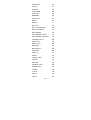
1
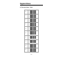
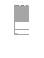
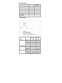
FI-300
Fixed-Mount Area Imager Scanner
User’s Manual
Contents
1.Configuring ....................................................................................... 1
1.1 Preface ....................................................................................... 1
1.2 Changing Scanner Settings with Programming Codes ............. 1
1.3 Changing Scanner Settings with Utility Tool ............................. 2
1.4 Factory Default Settings ............................................................ 2
2.Operating Settings ........................................................................... 3
2.1 Scanning Triggering ................................................................... 3
2.2 Time Out .................................................................................... 5
2.3 Good Read Mode....................................................................... 5
2.4 Buzzer Beep Tone ..................................................................... 5
2.5 Good Read Duration .................................................................. 7
2.6 Bad Read Message Settings ..................................................... 8
3.Imager Settings ................................................................................. 9
3.1 Imager Mode .............................................................................. 9
3.2 Firmware Version ....................................................................... 9
4. Programming Codes ..................................................................... 10
4.1 Factory Default ......................................................................... 10
4.2 RS232 Parameters Baud Rate ................................................ 11
4.3 USB HID Parameter................................................................. 15
4.4 Decoding Selection .................................................................. 16
Appendixes ........................................................................................ 27
A. Decimal Value Table ................................................................. 27
B. ASCII Table ............................................................................... 28
C. Readable Symbologies ............................................................. 29
D. Scan Map .................................................................................. 30
E. Test Symbologies ...................................................................... 31
F. Complement .............................................................................. 32
1. Configuring
1.1 Preface
How to configure this device: The Barcode
Programming Feature gives the possibility to change
the scanner settings with use programming codes.
1.2 Changing Scanner Settings with
Programming Codes
You can setup your device by scanning all necessary
programming codes for parameters that meet
applications. After these scans, the device will save
directly and permanently. To go back to the factory
default settings, just scans the programming code
factory default.
In order to change the scanner settings please follow
the sequence below:
1) Power-up the scanner.
2) Change scanner settings by scanning any of
the programming code that meet applications.
An Example:
For changing the Baud rate to 38400 only scan the
programming code that represents this.
After reading a valid programming code the scanner
will give a High beep and the green led indicator will
lights on.
At any moment, you can stop your programming and
read programming code factory default to go back to
default.
1
1.3 Changing Scanner Settings with
Utility Tool
Manufacturer has setup this scanner with the most
common used programming codes, it could be
possible that you need more advanced settings to use
the scanner without any problems into your application.
In this case you can setup your scanner by using the
advanced Utility Tool. This tool can be used with the
following operation systems: Windows98,
Windows2000, Windows XP en Windows Vista.
This Utility Tool can be delivered on request. Please
contact your dealer
1.4 Factory Default Settings
The factory default settings are shown with * and bold
in the followings sections
The readable and default enable symbologies list,
please see Appendixes C.
2
2. Operating Settings
2.1 Scanning Triggering
<Level>
A reading session begins (lighting and decode
processing on) when beam is activated and stops
when beam is deactivated.
Continuous Scanning
When the scanner is turned on a continuous reading
session begins (lighting and decode processing on).
Pulse
A reading session begins when beam is activated and
stays on until a period of inactivity lasting the time
specified by the timeout.
After the timeout, the scan engine turns off.
Flashing
Flashing mode allows power up the lighting and
decoding are on (no need to activate the trigger line)
and after a period of inactivity lasting the time specified
by the trigger timeout, the scanner starts flashing,
checking for a bar code to be read.
When a bar code is detected, the lighting and decoding
automatically turn on and stay on until another period
of inactivity (timeout), after the timeout the scanner
starts flashing again.
3
Autostand
This mode allows you to switch from Flashing trigger
mode to Level trigger mode.
Autostand begins in flashing mode: At power up the
lighting and decoding are on (no need to activate the
trigger line) and after a period of inactivity lasting the
time specified by the trigger timeout, the scanner starts
flashing.
To switch to Level trigger mode activate the trigger line
(press the trigger).
When in Level trigger mode, after a period of inactivity
lasting the time specified by the trigger timeout, the
scanner switches back to flashing mode.
Toggle
This mode allows lighting and decoding toggle when
the trigger line is activated.
First trigger activation = lighting and decoding on,
second trigger activation = lighting and decoding off.
Presentation
This mode allows power up lighting and decoding are
on. After a period of inactivity lasting the time specified
by the trigger timeout, the lighting turns off or is
dimmed. When a new bar code is presented the
lighting and decoding restart and stay on until another
period inactivity.
4
2.2 Time Out
<2 sec>
4 sec
6 sec
2.3 Good Read Mode
When active, the scan engine stops the reading
session after a successful decoding.
Note: This parameter is NOT used with continuous and
continuous + flashing modes.
<Active >
Not Active
2.4 Buzzer Beep Tone
2.4.1 Beep Tone Setup
<High >
Medium
Low
5
2.4.2 Good Read Beeps
<One Beep >
Two Beeps
None
2.4.3 Beep Duration
60 msec
<80 msec>
200 msec
Off
2.4.4 Timing
<During Transmission>
Before Transmission
After Transmission
6
2.5 Good Read Duration
2.5.1 Good Read Led Duration
<80 msec >
0.5 sec
1 sec
Off
2.5.2 Error Beep
<On >
Off
2.5.3 Setup Beep
<On>
Off
7
2.6 Bad Read Message Settings
<Default = "NOREAD" >
Active
<Not Active >
8
3. Imager Settings
3.1 Imager Mode
You can set the best reading performance depends on
the environment, your used application and type of
barcodes.
• Linear mode for decode 1D Barcodes.
• Area mode for decode 1D and 2D barcodes.
Area mode allows you to set the position of the FI-300
in any direction regardless of the orientation of the
barcode, and perform a good read on 1D and 2D
barcodes.
Linear mode allows you to increase your decoding
speed while scanning 1D barcodes. But, you need to
position the beam across all bars in the 1D barcode.
Linear imager
<Area imager>
Area imager
Bright Environment
Area imager with
Reflective Surface
3.2 Firmware Version
Display the firmware version of the scanner, please
scan below barcode.
Firmware Version
9
4. Programming Codes
4.1 Factory Default
The default RS232 settings are 57600 baud, 8 data
bits, and no parity.
The factory default settings are shown with bold
< > in the following pages.
To set the scanner parameters to factory
default
Set factory default
Reset all configuration parameters to their factory
default setting. After this reset you must select all
required parameters that meet applications.
Note: The “Set factory default” setting would return to
the original default setting instead of the customized
setting. That is, if you are using the USB HID interface,
your device will lose USB interface settings when the
“Set factory default” be set. Then you must to chapter
7.3 to re-configure USB HID mode setting barcode
again.
10
4.2 RS232 Parameters Baud Rate
4800
9600
19200
38400
<57600>
115200
4.2.1 Data Bits
Data Bits 7
<Data Bits 8>
4.2.2 Stop Bits
<Stop Bits 1>
Stop Bits 2
11
4.2.3 Parity
<None>
Even
Odd
4.2.4 Hardware/Software Protocols Timeout
Compose (ms): 500
<Compose (ms):1000>
Compose (ms): 1500
Compose (ms): 2000
Compose (ms): 2550
4.2.5 RS-232 Parameters–ENQ
<Not Active>
Active
<Default: 05H>
12
4.2.6 RS-232 Parameters–ACK
<Not Active>
Active
<Default: 06H>
4.2.7 RS-232 Parameters–NAK
<Not Active>
Active
<Default: 15H>
4.2.8 Software Protocol–XON/XOFF
Active
<Not Active>
13
4.2.9 Hardware Protocol–RTS/CTS
<Not Active>
Active, RTS idle after
each character
Active, RTS idle after
whole message
4.2.10 RS-232 Parameters-LRC
(Longitudinal Redundancy Check)
<Not Active>
Active
4.2.11 RS-232 Parameters-Inter-Character
Delay
<None>
10 ms
20 ms
30 ms
40 ms
50 ms
14
4.2.12 RS-232 Parameters-Inter-Message Delay
<None>
10 ms
30 ms
50 ms
80 ms
100 ms
4.3 USB HID Parameter
USB HID Mode
Note: The “Set factory default” setting (Chapter 7.1)
would return to the original default setting instead of
the customized setting. That is, if you are using the
USB interface, your device will lose USB HID interface
settings when the “Set factory default” be set. Then
you must to re-configure USB HID mode setting
barcode again.
15
4.4 Decoding Selection
4.4.1 Symbologies Selection
Australian Post ON
<Australian Post OFF>
AZTEC ON
<AZTEC OFF>
BPO ON
<BPO OFF>
Canada Post ON
<Canada Post OFF >
CODABAR ON
<CODABAR OFF>
Codablock A ON
16
<Codablock A OFF>
Codablock F ON
<Codablock F OFF>
CODE 11 ON
<CODE 11 OFF>
<CODE 39 ON>
CODE 39 OFF
CODE 93 ON
<CODE 93 OFF>
<CODE 128 ON>
CODE 128 OFF
<GS1-128 ON>
17
GS1-128 OFF
<DATAMATRIX ON>
DATAMATRIX OFF
DATAMATRIX - MIRROR ON
<DATAMATRIX - MIRROR OFF>
Dutch Post ON
<Dutch Post OFF>
<EAN-8 ON>
EAN-8 OFF
<EAN-13 ON>
EAN-13 OFF
18
<EAN 128 ON>
EAN 128 OFF
GS1 CC-A/B ON
<GS1 CC-A/B OFF>
GS1 CC-C ON
<GS1 CC-C OFF>
GS1 DataBar-Omni ON
<GS1 DataBar Omni OFF >
GS1 DataBar Limited ON
<GS1 DataBar Limited OFF>
GS1 DataBar Expanded ON
<GS1 DataBar Expanded>
19
Infomail ON
<Infomail OFF>
Interleaved 2 of 5 ON
<Interleaved 2 of 5 OFF>
Japan Post ON
<Japan Post OFF>
Matrix 2 of 5 ON
<Matrix 2 of 5 OFF>
MaxiCode ON
<MaxiCode OFF>
MicroPDF417 ON
<MicroPDF417 OFF>
20
MSI ON
<MSI OFF>
<PDF417 ON>
PDF417 OFF
Planet ON
<Planet OFF>
PLESSEY ON
<PLESSEY OFF>
Postnet ON
<Postnet OFF>
QR Code ON
<QR Code OFF>
21
Standard 2 of 5 ON
<Standard 2 of 5 OFF>
Sweden Post ON
<Sweden Post OFF >
Telepen ON
<Telepen OFF>
TLC 39 ON
<TLC 39 OFF>
<UPC-A ON>
UPC-A OFF
<UPC-E ON>
UPC-E OFF
22
4.4.2 Disable All Symbologies
If you want to disable all Symbologies, please
scan below programming code. Or you can scan
the “Off” option to disable individual symbologies.
Disable All Symbologies
Note: Do not reset individual parameters settings for
each symbology. When you enable a symbology, you
will recover the parameter settings stored in memory.
Anytime, you may reset to factory defaults by scanning
the programming code of “Set factory default” .
4.4.3 Multi Code
The multicode function is used configure the scanner
to read a series of bar codes and then transmit them
all at once.
<Not active>
Active
Active exclusive
Number of bar codes –
compose: 2
Number of bar codes –
compose: 3
23
Number of bar codes compose: 4
Number of bar codes –
compose: 5
Number of bar codes compose: 6
4.4.4 Activates user defined symbology
identifier (UDSI) transmission for all
symbologies.
[UDSI symbology id] <data>
<not transmitted>
UDSI transmitted
[UDSI symbology id] <data>
symbology
default identifier
Australia Post
P3
Aztec
D3
BPO
P2
Canada Post
P6
Codabar
B7
Codablock A
K0
24
Codablock F
K1
Code 11
C1
Code 39
B1
Code 93/93i
B6
Code 128
B3
DataMatrix
D0
Dutch Post
P4
EAN-8
FF
EAN-13
F
GS1-128
C9
GS1 Composite A/B
G0
GS1 Composite C
G1
GS1 DataBar
C3
GS1 DataBar Limited
C4
GS1 DataBar Expanded
C5
Interleaved 2 of 5
B2
Japan Post
P5
Matrix 2 of 5
B4
MaxiCode
D2
MicroPDF417
C8
MSI Code
B8
PDF417
C7
Planet
P1
Plessey Code
C2
Postnet
P0
QR Code
D1
Standard 2 of 5
B5
Sweden Post
P7
Telepen
C6
TLC 39
H0
UPC-A
A0
UPC-E
E0
25
4.4.5 Postambles
The scanner can be programmed to output Barcode
data according to the following format: [BAR CODE
DATA] [POSTAMBLE STRING]
Example:
To send a <ETX> after the Barcode, scan only
programming code <ETX>.
As a result, the scanner will give the following barcode
data output:
[BAR CODE DATA] [<ETX>]
Postamble None
<CR+LF >
CR
LF
TAB
SP
26
Appendixes
A. Decimal Value Table
0
1
2
3
4
5
6
7
8
9
27
B. ASCII Table
A
B
C
D
E
F
G
H
I
J
K
L
M
N
O
P
Q
R
S
T
U
V
W
X
Y
Z
28
C. Readable Symbologies
1D Symbologies
Symbologies
Readable
EAN/UPC
UCC/EAN128
ISBN
ISBT
Code 11
Code 39
Code 93/93i
Code 128
Interleaved 2 of 5
Matrix 2 of 5
Instustrial 2 of 5
Standard 2 of 5
Codabar
MSI
Plessey
Telepen
BPO
Codablock
Informail
Planet
TLC 39
Postnet
Postal codes
GS1-128
GS1 CC-A/B/C
GS1 DataBar
Omnidirectional
GS1 DataBar
Limited
GS1 DataBar
Expanded
○
○
○
○
○
○
○
○
○
○
○
○
○
○
○
○
○
○
○
○
○
○
○
Default
Enable
○
○
○
○
○
○
○
○
○
29
2D Symbologies
Symbologies
Readable
○
○
○
○
○
○
○
Data Matrix
PDF417
MicroPDF417
MaxiCode
QR code
Aztec
EAN.UCC
composite
Default
Enable
○
D. Scan Map
Symbology
Code 39
UPC / EAN
Data matrix
PDF417
Density
Minimum
Distance
(+/- 10%)
5.2 cm
2.0 cm
2.4 cm
4 cm
7 cm
4 cm
5.3 cm
3.8 cm
*
5.2 cm
3.5 cm
3 cm
0.125 mm
0.20mm
0.25mm
0.5mm
1mm
0.33 mm
0.191 mm
0.254 mm
0.381 mm
0.16 mm
0.254 mm
0.381 mm
30
Maximum
Distance
(+/- 10%)
12.1 cm
21.5 cm
26 cm
44 cm
82 cm
31 cm
16.2 cm
21 cm
28 cm
14.4 cm
22 cm
36 cm
E. Test Symbologies
Scan one or more of these barcodes to test barcode
symbologies you enabled.
Codabar
Code 39
Code 93
Code 128
DataMatrix
EAN 8
1234 5670
EAN13
1 234567 890128
EAN 128
Interleaved 2 of 5
MSI code
PDF417
31
GS1 DataBar
Omnidirectional
GS1 DataBar Omni Stacked
GS1 DataBar Expanded
GS1DataBar Expanded
Stacked
GS1 DataBar Limited
UPC A
0
12345 67890
5
UPC E
0
123456 5
F. Complement
AIM identifier transmitted
AIM identifier not transmitted
32
Set factory default
Engine Firmware Version
Scanner Decoder Firmware Version
Due to Champtek’s / Scantech ID’s continuing product
improvement programs, specifications and features are
subject to change without notice.
October 2010
33