1
Oakley Sound Systems
Power Supply Unit (PSU)
PCB Issue 3
Project Builder's Guide
V3.0
Tony Allgood
Oakley Sound Systems
CARLISLE
United Kingdom
1
Introduction
This is the Project Builder's Guide for issue 3 of the PSU circuit board from Oakley Sound.
This document contains the circuit diagram of the completed board, a full parts list for the
components needed to populate the board and some basic testing methods.
You will also need the PSU User Manual which gives details on how to use the module as
well as example wiring diagrams. This can be found on the Oakley PSU webpage.
For general information regarding where to get parts and suggested part numbers please see
our useful Parts Guide at http://www.oakleysound.com/parts.pdf.
For general information on how to build our modules, including circuit board population,
mounting front panel components and making up board interconnects please see our
Construction Guide at http://www.oakleysound.com/construct.pdf.
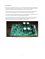
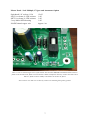
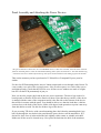
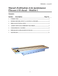
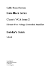
The issue 3 Oakley PSU board awaiting fitting to the front panel.
2
Which Power Devices?
The two off board transistors are awesomely chunky devices in a TO-3P package. The devices
I recommend are TIP35C for the NPN and TIP145 or TIP147 for the Darlington PNP. I buy
Multicomp's MOSPEC ones available from Farnell.
If you are using the standard TIP devices you may also need two TO-3P mounting kits. This
comprises usually of an insulating pad or plate and an insulating bush which looks like a little
top-hat. The kit may also have a sachet of some heatsink compound if the insulation material
is made from mica. Newer kits contain a pad made from a fibre glass cloth which is usually
grey, but I have seen white and pale green ones too. This pad has two functions: Firstly it
insulates the metal tab of the housing, which is internally connected to the collector of the
transistor, from the panel or heatsink. Secondly it improves thermal transfer because it
squashes itself into the two surfaces so it doesn't normally need any heatsink paste. The
insulating bush is like a little top hat made from a very brittle plastic. This will sit in the hole of
the device and insulate the mounting screw from the metal tab. The MOSPEC TIP35 and
TIP145 devices need no insulating bush, only the insulating pad, since the mounting hole is
already insulated as part of the device.
Alternatively, you can use any large power NPN and PNP device you fancy, but just make
sure you have wired the correct pins to the right pads on the PCB. Remember, for the PNP
device you need to ensure that the minimum hfe is sufficiently high. This is because there is a
direct relationship between the current draw on the power supply and the current that is
needed to drive the transistor. I would recommend devices with hfe of 80 or more. Using a
Darlington device for the PNP transistor will ensure that you have enough gain – although too
much gain could lead to instability. Remember also that older TO-3 packages will need special
mounting kits with bushes, solder tags and insulating pads.
3
Parts List
For general information regarding where to get parts and suggested part numbers please see
our useful Parts Guide at the project webpage or http://www.oakleysound.com/parts.pdf.
The components are grouped into values, the order of the component names is of no particular
consequence.
A quick note on European part descriptions:
For resistors: R is shorthand for ohm. K is shorthand for kilo-ohm. M is shorthand for megaohm
For capacitors: 1uF = 1,000nF = 1,000,000pF. Sometimes the F is not included on the circuit
diagram to indicate a capacitor's value, ie. 100n = 100nF.
To prevent loss of the small ‘.’as the decimal point, a convention of inserting the unit in its
place is used. eg. 4R7 is a 4.7 ohm, 4K7 is a 4700 ohm resistor, 4n7 is a 4.7 nF capacitor.
Resistors
R13 is not a resistor but a wire link. You can use solid core copper wire or a discarded
resistor lead clipping. Simply solder the wire so that it connects both pads of R13 together.
5% 1/4W carbon or better (1/4W 1% metal film is recommended)
1K
4K7
R1, R11
R4, R5, R10
1% 1/4W metal film
10K
12K
R7, R9, R8
R6, R12
2W metal film or wirewound (5% or better)
Yamaha PA-20:
1R
R2, R3
Yamaha PA-30:
0R82
R2, R3
4
Capacitors
22pF low-K ceramic 2.5mm
330p low-K ceramic 2.5mm
100nF axial ML ceramic
10uF, 35V electrolytic
22uF, 35V electrolytic
470uF, 35V electrolytic
1800uF, 35V electrolytic
C4
C5
C1, C2, C9
C3, C6, C10, C11
C12
C15
C7, C8, C13, C14
Note: C7, C8, C13 and C14 are 105 degree Celsius radial types and have standard wire ended
leads. Lead spacing is 7.5mm. I recommend Panasonic type EEUFC1V182 but any decent 105
degree part can be used that will fit on the board will do.
Alternatively, you can use two 3300uF, 35V instead. Fit these to positions C8 and C14 and
leave C7 and C13 empty.
Integrated Circuits
7805 5V 1A regulator
LM723CN 100mA voltage regulator
OP177GPZ single precision op-amp
U1
U2
U3
Good quality DIL sockets are recommended. You need one 14-pin and one 8-pin.
Discrete Semiconductors
1N4004 rectifier diode
1N5401 rectifier diode
TIP35C NPN transistor
TIP145 or TIP147 PNP Darlington transistor
BC560 PNP transistor
D1, D2, D3, D4, D5, D6, D7, D8
D9, D10, D11, D12
Q1
Q2
Q3
Do not solder the two power transistors until the board is ready to be mounted on its panel
There are three LEDs that can be fitted to the board to indicate power status. However, these
can be optionally fitted to any front panel you are using. In this case I would recommend that
you fit 2-way 0.1” KK or MTA headers to the board in place of the LEDs.
5mm red LED
5mm green LED
5mm orange LED
AC
-VE
+VE
Trimmer
10K multiturn trimmer
AD
5
Miscellaneous
2A antisurge 20mm fuse
20mm fuseholder PC mount
4-way screw terminal 5mm
F1, F2
F1, F2
POWER, SWITCH, OP1, OP2
Heatsink compound if you are using the TIP devices with a clear mica insulating pad.
TO-3P mounting kits (2 off) for mounting the TIP power devices. Note if you have bought
MOSPEC power devices the mounting hole is already insulated from the substrate of the
transistor. This means you do not need to purchase a 'top hat' bush – all you need is a TO-3P
insulating pad.
Connecting wire of your choice. I use 22AWG (0.5 sq.mm) appliance wire for all power
connections.
Mounting hardware for Master Panel
M3 20mm Countersunk screws
M3 10mm Countersunk screws
M3 star washers
M3 washers
M3 hex threaded 10mm spacers
M3 hex nuts
4 off
2 off
10 off
2 off
4 off
6 off
Mounting hardware for 19” rack panel
M3 6mm pan head screws
M3 20mm pan head screws
M3 hex threaded 10mm spacers
M3 star washers
M3 washers
M3 hex nuts
4 off
2 off
4 off
10 off
2 off For power devices
2 off For power devices
And any mounting hardware for the Dizzy boards if needed.
Optional Extras
Power switch DPST
3-way connector
LED clip
1 off
1 off
1 off
Power on
Connector to the line-lump
6
Master Panel - Jack Multiple, CV/gate and Attenuator Option
Switchcraft 1/4” sockets 112A
47K 5% or better, 0.25W resistors
4K7 5% or better, 0.25W resistors
3-way Molex/MTA housing
20AWG tinned copper wire
12 off
1 off
1 off
1 off
Approx. 1m
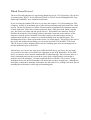
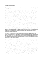
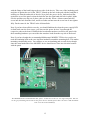
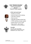
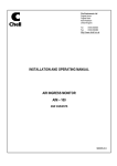
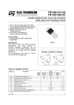
Here we can see bottom right corner of the board. Note that the SWITCH terminal block has not been
fitted as this board will be fitted to a unit that has a mains transformer directly wired to the board. Two
links are fitted so that a standby switch does not need to be fitted.
R13 is also a wire link so as to directly connect the mounting hole pad to ground.
7
Circuit Description
The design is based around some very traditional methods so there are no claims for originality
with this board.
The line lump outputs a two phase AC signal each one with a peak of nearly 25V with respect
to its centre tap output. The difference between the two phases is that one is completely out of
phase with the other. It's a bit like an audio balanced output in that respect. Both phases
should be present for the power supply to work correctly.
Each phase is separately fused. Note that the fuses should be anti-surge, or ‘slo-blo’. The
standard convention is for a ‘T’ in front of the value, where T is for time lag. For example,
T2A would mean a two ampere anti-surge fuse. Anti-surge fuses have a higher thermal mass
than fast blow fuses to prevent them blowing when they see a short burst of current. The
inrush current when the supply is first switched on is completely normal and we don’t want
our fuses blowing at that point.
D8, C12 and R12 provide a low current DC feed to a standby AC in LED. This lights up
whenever the line lump is connected and powered up. It is wired in before the modular's
power switch to remind you that the power on switch is actually a standby switch and does
not switch the line lump off.
It is possible to run the Oakley PSU module on a single phase. This means that the unit could
be connected to a single output AC adapter, ie. one with just two leads to pins 1 and 2.
However, the regulators and the AC adapter will have to work very hard in this application. It
is therefore not recommended to run the PSU in single phase unless the output current is
going to be less than 250mA or so.
The raw AC is fed to a bridge rectifier based around D9, D10, D11 and D12. This is the
classic bridge rectifier circuit. Although it is drawn somewhat differently in the schematic than
the usual ‘bridge’ style. If you think about a diode as passing current through it just one way,
you should be able to work out why the voltage across C13 and C14 ends up as only positive,
and across C7 and C8 as only negative.
I have used 1N5401 diodes in this place. These are 3A devices and are plenty large enough to
cope with any abuse the power supply is given.
The outputs of the rectifiers supply current to the two smoothing capacitors. These act as
reservoirs of charge when the AC voltage dips below its peak output. You can think about the
rectifiers as merely topping up the reservoirs 100 times a second (120 in North America),
whilst the capacitors actually provide the power to keep the modular powered.
The smoothing capacitors are generously rated both in terms of voltage and capacitance. It is
essential that you use good quality components here and that they have sufficiently high ripple
current rating. Since this PSU could possibly be supplying nearly 1A per supply rail, a single
smoothing capacitor would need to have twice that to be on the safe side. A cheaper and less
rugged capacitor will overheat and won’t last as long. The issue 3 Oakley PSU uses two
smoothing capacitors in parallel per supply rail. The current through each capacitor is,
8
therefore, roughly half that what it would be with just one larger smoothing capacitor per rail.
This reduces the internal heating of the capacitors thus increasing longevity, as well as making
the whole PSU assembly physically less high.
The voltage across the smoothing capacitors is fairly constant but it is not stable enough to
drive a modular synth. Modular synths need to have a regulated supply so that they stay in
tune and behave in a predictable fashion whatever patches are selected. The regulators smooth
out the voltage across the big capacitors even more and will produce a constant, low ripple
+15V and -15V output.
Both of the regulators work in a similar way. You can think of them like a person controlling
the speed of a water wheel. If the wheel runs too fast, the water flowing over the wheel is cut
back by closing the sluice gate. If it runs too slowly, then the water flow is increased by
opening the gate. The person uses his own eyes to monitor the speed of the wheel, and will
make adjustments to the sluice accordingly. Now the wheel speed will depend on two things
primarily, firstly the water rate, but also the load on the wheel itself. If the wheel needs to do
more work it will slow down unless the water rate is increased.
The regulated power supply must also control its output with changes of load [ie. the number
of synth modules in your system] and the input voltage [ie. fluctuations in the line lump’s
output].
Before we talk about the circuit in more detail, I ought to say why I haven’t used the more
common and I might add cheaper 7815 and 7915 regulators. The main reason is down to
controllable current limiting. The 78XX and 79XX series do not feature this. In fact, if you
were to short out a 7815 to ground, it would take around 1.7A from the supply and would
heat up until the inbuilt thermal limiter kicked in. 1.7A may well be high enough to damage
any connected transformer or line lump, to say nothing of the rectifiers and smoothing
capacitors that would have to supply this current. By using the LM723 and a few external
components we put the control back in the hands of the builders of the circuit.
Let us look at the positive regulator first since this actually also controls the negative rail too.
The circuit is built around the venerable LM723 chip, U2. It contains pretty much everything
you need to make a small regulator, including precision voltage reference, feedback control
systems and a current limiter. However, it doesn’t have a very big output current capacity so
to use it for anything greater than 100mA, one needs to use an external pass transistor, Q1.
The pass transistor is analogous to our sluice gate. The resistance of the pass transistor is
effectively changed by the voltage at its base (pin 1). Decrease the voltage at its base with
respect to its emitter (pin 3) and the transistor will increase its effective resistance and the
output voltage of the PSU will drop.
The base voltage is controlled by the internal electronics of the LM723, but this in turn
responds to the feedback from the output of the power supply. The feedback path is
analogous to the sluice gate man’s visual record of the water wheel’s motion. In this case a
fraction of the output signal is fed back into the LM723 at pin 4. The electronics will
determine whether to make the base drive for Q1 higher or lower depending on what it ‘sees’.
The ADJ trimmer adjusts the fraction of the output voltage pin 4 will see and thus controls the
overall output voltage.
9
R2 forms an important part of the current limiting circuit. When current travels through this
resistor a voltage develops across it. When the voltage approaches 630mV, ie. 630mA
through the resistor, the internal electronics in the LM723 starts to pull down the base voltage
on Q1. This effectively lowers the output voltage to make sure the current doesn’t climb much
above that value.
The value of R2 (and also R3) will determine the actual value of the current limit. For
example, a 1R resistor will set the current limit to be around 630mA and a 0.82R resistor will
make it around 770mA. The resistor value is chosen so that it will develop 630mV across it
when your chosen current limit would be going through it.
Ilimit = 0.63V/Rlimit
Ilimit is the current limit value in amperes and the Rlimit is the value in ohms of the resistor.
However, there are several things to be taken into consideration should you decide to increase
the current limit above the values I have chosen.
Firstly, you need to ensure your transformer will be able to handle the additional current you
are asking from it. The simple rule of thumb is:
Iac = 1.8 x Idc.
Where Iac is the steady state AC current in the transformer's secondary coil, and I dc is the
current taken by the load connected to the +15V and -15V rails. For example: The Yamaha
PA-20 can supply 0.94A of alternating current into a simple resistative load from each of its
two outputs. But by the time the output of the PSU has been rectified and smoothed the DC
current taken should not exceed 0.52A on a continuous basis.
Secondly, the amount of current needed to drive the pass transistors, Q1 and Q2, is directly
related to the amount of current draw on the supply lines. Thus to ask for more from the
supply would be to ask more from the 723 on the positive rail and the op-amp on the negative
rail. The actual relationship between load current and drive current is related to hfe or the gain
of the pass transistor. Choosing a pass transistor with too little gain will mean that you cannot
obtain your required current. The recommended TIP35C and TIP145 devices have been tested
to work with a supply that can supply up to 1.1A, ie. R2 and R3 are both 0.56R.
Thirdly, the printed circuit board's copper tracks are not thick enough to pass huge amounts of
current.
Fourthly, you need to consider how you are going to get rid of the extra heat the power
devices will develop. The amount of heat given out by those devices is not only dependant on
the current taken by the output load but also the supply voltage. The latter being dependant on
the transformer being used and your local mains voltage.
The 3U wide 5U high panel design has only been tested to work with a maximum of 0.52A
per rail when driven from a PA-20 or PA-30. The 4U 19” panel is capable of considerably
more – it has been tested up to 0.94A with 25V across the smoothing capacitors. However, I
10
would advise you to do your own experiments carefully otherwise you run the serious risk of
overheating.
Finally, I think modular systems work better with a number of smaller power supplies rather
than one big one. This is because as power is distributed around a large modular it gets
'corrupted' by the connected modules and the cabling. The cables have resistance and as
current flows through the cables the voltage at the end of the cable gets reduced. The more
current that flows and the longer the cable the worse the problem.
Having multiple power supplies does create the not insignificant question of what to do with
the multiple grounds you will now have in your system. However, I would like to deal with
this in the User Manual which covers the application of the power supply module.
Now let us look in more detail at the negative part of the power supply. The negative supply
works in a similar way to the positive regulator but uses an op-amp, U3, and discrete
components. The reference for the negative rails comes not from a precision reference but
from the output of the +15V regulator. This means that the negative output voltage will track
the positive one, but not vice versa I should add.
The op-amp is wired as a simple inverting amplifier although its difficult to see this at first
glance. The input is via R9 which is connected to the +15V output. The feedback is provided
via R8 which is connected to the negative supply output. The output of the op-amp drives the
base of the pass transistor, Q2, via R11, which in turn controls the level of the negative
output. Q2, a TIP145, is a PNP Darlington transistor. This is actually two transistors in one
enclosure – but it can treated as one device with a larger than normal current gain (hfe) and
twice than normal base-emitter voltage of 1.2V. Having a high gain requires only a small
amount of drive current from the op-amp via R11 even when the load on the power supply is
relatively high.
U3 will act so that its output will force all the current flowing through R9 to be passed onto
R8. This is one of the op-amp golden rules; that is, no current shall flow into the input pins so
long as feedback is maintained. To do this the op-amp must force the pass transistor to pass
enough current though it to establish exactly -15V at the output.
Q3 and R3 form part of the current limit circuit. If the voltage across R3 exceeds 640mV then
Q3 will turn on dragging current away from Q2’s base and thus lowering the output voltage of
the negative rail accordingly.
The op-amp U3 derives its positive power from its own 5V supply based around a simple
7805 regulator chip. This allows the negative regulator to function correctly when the +15V
rail is under stress and allows the negative rail to fall gracefully when the mains power is
switched off.
D1, D7, D2 and D6 protect the +15V and -15V output rails from a variety of naughties. On
power down any excess current left in the modular will be shunted to the smoothing caps and
not damage the now un-powered power supply components. Also, they also prevent the
negative rail from going positive should the negative rail die for some reason. And vice versa
too.
11
Panel Assembly and Attaching the Power Devices
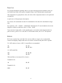
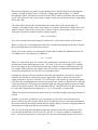
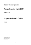
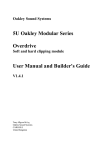
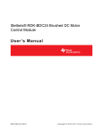
The powered devices shown here are two MOSPEC devices. This issue 2 board, issue has been removed
from the heatsink panel to show the insulated mounting holes of the TO-3P devices. Note that both the big
transistors have been soldered from the top side of the board with the leads coming up from the bottom.
This section assumes you have purchased a 3U Schaeffer or Frontpanel Express panel or
similar.
For the four PCB mounting holes, insert a 20mm countersunk screw through each of them. Fit
a star washer over each of the exposed screws. Now fit a hex spacer over each of the screws
and tighten firmly. Check that the PCB fits over all four screws without too much of a fight,
but don’t fit the PCB permanently in just yet.
Now you need to prepare the leads on the two power transistors. The three legs need to be
bent upwards so that the PCB can be fitted over them. Note that the top surface of the device
is marked with the name of the component and it is the flat side on the bottom of the device
that will be in contact with the panel. You should be able to see that the leads have a thicker
section close to the body of the device. Make a 90 degree bend upwards at a point 1mm away
from this thicker section. Do this for all three legs of the device.
If you are using TIP device with a metal mounting plate check that the mounting bush ('top
hat') fits through the two holes in the panel that the power devices will be attached to. If it
doesn't fit, don't force it in but widen the hole slightly with a reamer or suitable twist drill.
Make sure all the swarf is cleaned away. Now place the bush into the hole of the transistor,
12
with the flange of the bush lying on the top side of the device. Take one of the insulating pads
and place it against the rear of the TIP35C. Match up the hole in the pad with the bush that is
sticking out from the underside of the tab. Now place the power device, bush and pad flat
against the rear of the panel so that the bush fits into the right hand side hole in panel. Make
sure the pad does not slip out of place when you do this. Insert a 10mm countersunk M3
screw into the hole from the front, and fit a washer and nut onto the screw but do not tighten
fully. Do the same for the TIP145 in the left hand hole.
Now if you have done all this correctly, you should find that the when the power supply PCB
is fitted back onto the four screws, you can coax the power devices’ legs through the
respective pads on the board. With both the board and transistors secured to the panel with
their mounting hardware you can solder the transistor leads from the top side of the board.
Note if you have bought the recommended Multicomp's MOSPEC TIP devices you do not
need the insulating bush as the case itself has insulation around the mounting hole. This makes
mounting considerably easier. You still have to use an insulating pad on each device though
since the metal underside of the MOSPEC device should never come into electrical contact
with the panel.
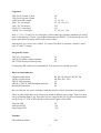
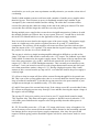
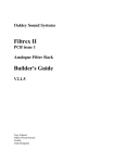
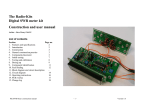
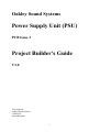
The MOSPEC devices mounted onto their panel – in this case it's the 19” 4U high rack panel. You can
see the grey insulating sheets between the power devices and the panel. This is an issue 2 PSU board but
issue 3 can be treated similarily.
13
Master Module: Jack Multiple and Attenuator Option
Fit twelve Switchcraft sockets into the spaces on the Master Panel. Align them so that the
bevel faces to the top right as you look at the back of the unit. With a single piece of 20SWG
tinned solid core wire connect all the earth lugs together on the right hand column. Now do
the same on the left hand column.
Now connect all the signal lugs, marked as T on the body of the socket, on the first four of the
right hand column of sockets. Then do the same on the left hand row.
You should now have four vertical wires, two running down the top four sockets, and two
running down over six. Your multiples are now complete.
The KEY CV and GATE sockets now need to be connected to the Oakley Dizzy buss. Use a
three way 0.1” Molex or MTA100, as described in the Dizzy User Guide, to connect the
signal lugs on these two sockets to the CV and Gate buss.
The 10:1 attenuator is simply made. Connect the signal lug on the right hand socket (IN) to
the signal lug of the left hand socket (OUT) with a 47K resistor. Then solder a 4K7 resistor
from the signal lug of the left hand socket to the earth lug of the same socket. And that's it!
14
Testing and Calibration
Note all testing must be done with the heatsink or panel attached to the power devices.
After wiring the unit according to the instructions given in the Users Manual you should apply
power to the unit. Check that no device is running hot. Any sign of smoke or strange smells
turn off the power immediately and recheck the all the external wiring first, and then the
components on the board. Both the +VE and -VE LEDs should be lit and neither should be
too bright or too dim.
With a multimeter, check the DC voltage across the +15V and -15V output terminals. You
should get around 30V or so. Adjust the trimmer so that you get exactly 30.00V. Now
measure the voltage across the +15V and one of the 0V terminals. This should read 15.0V or
very close to it. Check that the voltage across -15V and 0V is -15.0V. It is advisable that the
+VE and -VE LEDs are fitted for this adjustment, or that at least one Oakley or MOTM
module is connected up to the power supply board. This is to ensure that there is some current
running through the series pass devices (Q1 & Q2) which allows them to work properly.
If all is well, then it is time to check the current limit. Put your multimeter into current mode.
Use the 2A or 10A setting. Now put your probes across the +15V and 0V terminals. The
meter should read 630mA (for current limit resistors of 1R) or 780mA (for current limit
resistors of 0R82). The red LED should go out only when the probes are in place. There is a
problem if the LED does not come on again when the probes are removed. Now do the same
for the -15V and 0V terminals. This time we should get a slightly higher reading of around
720mA. (for 1R resistors) or 870mA (for 0R82 resistors). This time, the green LED should go
out.
While doing the current limit check you may notice the power devices getting warm. This is
perfectly normal.
If all is well, everything is probably working and you can now connect your new supply up to
your modules.
The output voltages will vary a little with load. That is, it will change marginally depending on
how many modules you connect up to the power supply board. Feel free to re-adjust the
trimmer when you add more modules to your system.
Tony Allgood at Oakley Sound
Cumbria, UK
© April 2014
15