Download S3FN41F External Interrupt


Transcript
S3FN41F
External Interrupt
Revision 1.00
August 2012
Appli cat i on Not e
2012
Samsung Electronics Co., Ltd. All rights reserved.
Important Notice
Samsung Electronics Co. Ltd. (“Samsung”) reserves the
right to make changes to the information in this publication
at any time without prior notice. All information provided is
for reference purpose only. Samsung assumes no
responsibility for possible errors or omissions, or for any
consequences resulting from the use of the information
contained herein.
This publication on its own does not convey any license,
either express or implied, relating to any Samsung and/or
third-party products, under the intellectual property rights of
Samsung and/or any third parties.
any information provided in this publication. Customer shall
indemnify and hold Samsung and its officers, employees,
subsidiaries, affiliates, and distributors harmless against all
claims, costs, damages, expenses, and reasonable attorney
fees arising out of, either directly or indirectly, any claim
(including but not limited to personal injury or death) that
may be associated with such unintended, unauthorized
and/or illegal use.
Customers are responsible for their own products and
applications. "Typical" parameters can and do vary in
different applications. All operating parameters, including
"Typicals" must be validated for each customer application
by the customer's technical experts.
WARNING No part of this publication may be reproduced,
stored in a retrieval system, or transmitted in any form or by
any means, electric or mechanical, by photocopying,
recording, or otherwise, without the prior written consent of
Samsung. This publication is intended for use by designated
recipients only. This publication contains confidential
information (including trade secrets) of Samsung protected
by Competition Law, Trade Secrets Protection Act and other
related laws, and therefore may not be, in part or in whole,
directly or indirectly publicized, distributed, photocopied or
used (including in a posting on the Internet where
unspecified access is possible) by any unauthorized third
party. Samsung reserves its right to take any and all
measures both in equity and law available to it and claim full
damages against any party that misappropriates Samsung’s
trade secrets and/or confidential information.
Samsung products are not designed, intended, or authorized
for use in applications intended to support or sustain life, or
for any other application in which the failure of the Samsung
product could reasonably be expected to create a situation
where personal injury or death may occur. Customers
acknowledge and agree that they are solely responsible to
meet all other legal and regulatory requirements regarding
their applications using Samsung products notwithstanding
警 告 本文件仅向经韩国三星电子株式会社授权的人员提供,
其内容含有商业秘密保护相关法规规定并受其保护的三星电
子株式会社商业秘密,任何直接或间接非法向第三人披露、
传播、复制或允许第三人使用该文件全部或部分内容的行为
(包括在互联网等公开媒介刊登该商业秘密而可能导致不特
定第三人获取相关信息的行为)皆为法律严格禁止。此等违
法行为一经发现,三星电子株式会社有权根据相关法规对其
采取法律措施,包括但不限于提出损害赔偿请求。
Samsung makes no warranty, representation, or guarantee
regarding the suitability of its products for any particular
purpose, nor does Samsung assume any liability arising out
of the application or use of any product or circuit and
specifically disclaims any and all liability, including without
limitation any consequential or incidental damages.
Copyright 2012 Samsung Electronics Co., Ltd.
Samsung Electronics Co., Ltd.
San #24 Nongseo-Dong, Giheung-Gu
Yongin-City, Gyeonggi-Do, Korea 446-711
Contact Us: como.jin@samsung.com
Home Page: http://www.samsungsemi.com
Trademarks
All brand names, trademarks and registered trademarks belong to their respective owners.
Exynos, Exynos4210, FlexOneNAND, and OneNAND are trademarks of Samsung Electronics.
ARM, Jazelle, TrustZone, and Thumb are registered trademarks of ARM Limited.
Cortex, ETM, ETB, Coresight, ISA, and Neon are trademarks of ARM Limited.
Java is a trademark of Sun Microsystems, Inc.
SD is a registered trademark of Toshiba Corporation.
MMC and eMMC are trademarks of MultiMediaCard Association.
JTAG is a registered trademark of JTAG Technologies, Inc.
Synopsys is a registered trademark of Synopsys, Inc.
I2S is a trademark of Phillips Electronics.
I2C is a trademark of Phillips Semiconductor Corp.
MIPI and Slimbus are registered trademarks of the Mobile Industry Processor Interface (MIPI) Alliance.
All other trademarks used in this publication are the property of their respective owners.
Chip Handling Guide
Precaution against Electrostatic Discharge
When using semiconductor devices, ensure that the environment is protected against static electricity:
1. Wear antistatic clothes and use earth band.
2. All objects that are in direct contact with devices must be made up of materials that do not produce static
electricity.
3. Ensure that the equipment and work table are earthed.
4. Use ionizer to remove electron charge.
Contamination
Do not use semiconductor products in an environment exposed to dust or dirt adhesion.
Temperature/Humidity
Semiconductor devices are sensitive to:
Environment
Temperature
Humidity
High temperature or humidity deteriorates the characteristics of semiconductor devices. Therefore, do not store or
use semiconductor devices in such conditions.
Mechanical Shock
Do not to apply excessive mechanical shock or force on semiconductor devices.
Chemical
Do not expose semiconductor devices to chemicals because exposure to chemicals leads to reactions that
deteriorate the characteristics of the devices.
Light Protection
In non- Epoxy Molding Compound (EMC) package, do not expose semiconductor IC to bright light. Exposure to
bright light causes malfunctioning of the devices. However, a few special products that utilize light or with security
functions are exempted from this guide.
Radioactive, Cosmic and X-ray
Radioactive substances, cosmic ray, or X-ray may influence semiconductor devices. These substances or rays
may cause a soft error during a device operation. Therefore, ensure to shield the semiconductor devices under
environment that may be exposed to radioactive substances, cosmic ray, or X-ray.
EMS (Electromagnetic Susceptibility)
Strong electromagnetic wave or magnetic field may affect the characteristic of semiconductor devices during the
operation under insufficient PCB circuit design for Electromagnetic Susceptibility (EMS).
Revision History
Revision No.
Date
1.00
August 08, 2012
Description
Creation
Author(s)
Younghee Jin
Table of Contents
1 INTRODUCTION............................................................................................. 10
1.1 Overview ....................................................................................................................................................10
1.2 General Description ...................................................................................................................................10
1.3 Reference...................................................................................................................................................10
2 EXTERNAL INTERRUPT ............................................................................... 11
2.1 EXI Pin Configuration .................................................................................................................................11
2.2 External Interrupt Mapping .........................................................................................................................12
2.3 External Interrupt Enable ...........................................................................................................................15
2.4 External Interrupt Handler ..........................................................................................................................17
2.5 External Interrupt Configuration .................................................................................................................18
3 EXAMPLE....................................................................................................... 20
3.1 Hardware ....................................................................................................................................................20
3.2 Software .....................................................................................................................................................22
List of Figures
Figure
Number
Figure 1
Figure 2
Figure 3
Figure 4
Figure 5
Figure 6
Figure 7
Title
Page
Number
Mapping between WSRCx (WIx) and EXIn ...........................................................................................14
WI0 Interrupt and WSI0 Vector ..............................................................................................................15
WIx Interrupt and WSIx Vector ..............................................................................................................16
Flow Chart for External Interrupt ............................................................................................................18
Block Diagram of S3FN41F Evaluation Board .......................................................................................20
Board Condition for Example .................................................................................................................21
The Execution Message Through UART ...............................................................................................23
List of Tables
Table
Number
Table 1
Table 2
Table 3
Table 4
Title
Page
Number
External Interrupt Pins .............................................................................................................................11
CM_WCR0 (from WSRC0 to WSRC3) ...................................................................................................12
CM_WCR1 (from WSRC4 to WSRC7) ...................................................................................................12
External Interrupt/Wake-Up Sources and Pin Assignment .....................................................................13
List of Examples
Example
Number
Example 1
Example 2
Example 3
Title
Page
Number
External Interrupt Handler ..................................................................................................................17
I/O Configuration Function .................................................................................................................22
EXI10 (WI0) and EXI0 (WI1) Interrupt Configuration .........................................................................23
S3FN41F_Application Note_REV1.00
1
1 Introduction
Introduction
1.1 Overview
This document describes about the external interrupt of S3FN41F. It includes the configuration to use the external
interrupt and the example.
1.2 General Description
S3FN41F has 16 external interrupt pins (EXI0 to EXI15). The maximum number of external interrupt to enable at
the same time is eight.
16 external interrupt pins (EXI0 to EXI15)
Selectable external interrupts (up-to eight)
Support falling/rising edge
Interrupt enable/disable control
The external interrupt can be used to execute any specific operation or wakeup from low power mode when the
external event is detected. The signal to trigger external event should be asserted through EXI (External Interrupt
Pin). Refer to chapter 26.5 External Interrupt Input Characteristics in S3FN41F user's manual for the detailed
condition of external event signal.
1.3 Reference
You can download the related document and example code from Samsung web site.
http://www.samsung.com/global/business/semiconductor/product/microcontroller/detail?productId=6784&iaId=804
S3FN41F User's Manual
S3FN41F Board Manual
External Interrupt Example (Software)
10
S3FN41F_Application Note_REV1.00
2
2 External Interrupt
External Interrupt
2.1 EXI Pin Configuration
As you can see, a pin can be defined as one function pin among maximum 4 functions. If you want to use the
external interrupt, input pins for external event signal should be configured as EXI function by IOCONF register
before enabling each external interrupt. You can set the target function, external interrupt, using the mode
registers (IOCONF_MLR0/1, IOCONF_MHR0/1).
EXI0 pin configuration
IOCONF_MLR0 01'b << 30 (Write 01'b into IO0_15_FSEL field to assign as F1 function)
EXI11 pin configuration
IOCONF_MLR0 10'b << 12 (Write 10'b into IO0_6_FSEL field to assign as F2 function)
EXI8 pin configuration
IOCONF_MHR1 11'b << 6 (Write 11'b into IO1_19_FSEL field to assign as F3 function)
Table 1
External Interrupt Pins
IO Group 0/1
Function Number
F0
F1
F2
F3
Pin Number
IO0x.y_FSEL[1:0]
00'b
01'b
10'b
11'b
13
IO0.6_FSEL[1:0]
P0_6
PWMOFF
EXI11
ADTRG
18
IO0.7_FSEL[1:0]
P0_7
SSPRX0
VLCD1
EXI12
19
IO0.8_FSEL[1:0]
P0_8
SSPTX0
VLCD2
EXI13
22
IO0.11_FSEL[1:0]
P0_11
TPWM2
COM0
EXI14
23
IO0.12_FSEL[1:0]
P0_12
TCAP2
COM1
EXI15
24
IO0.13_FSEL[1:0]
P0_13
TCLK2
COM2
TPWM2
25
IO0.14_FSEL[1:0]
P0_14
COP
COM3
TPWM3
26
IO0.15_FSEL[1:0]
P0_15
EXI0
COM4_SEG0
PWM0
27
IO0.16_FSEL[1:0]
P0_16
EXI1
COM5_SEG1
PWM1
35
IO0.24_FSEL[1:0]
P0_24
TCLK5
SEG9
EXI2
38
IO0.27_FSEL[1:0]
P0_27
TCLK6
SEG12
EXI3
39
IO0.28_FSEL[1:0]
P0_28
TCAP6
SEG13
EXI4
53
IO1.1_FSEL[1:0]
P1_1
USARTRX0
SEG18
EXI5
54
IO1.2_FSEL[1:0]
P1_2
USARTTX0
SEG19
EXI6
70
IO1.18_FSEL[1:0]
P1_18
AIN9
COP8
EXI7
71
IO1.19_FSEL[1:0]
P1_19
AIN10
COP4
EXI8
72
IO1.20_FSEL[1:0]
P1_20
EXI9
OP0_P
TPWM7
74
IO1.22_FSEL[1:0]
P1_22
EXI10
OP0_O
TPWM1
11
S3FN41F_Application Note_REV1.00
2 External Interrupt
2.2 External Interrupt Mapping
If you choose which external interrupt you use, you should register target external interrupt to CM_WCR0 or
CM_WCR1 (Wakeup Control Register 0 or 1). You can register up-to eight sources from WSRC0 to WSRC7.
10
9
8
7
6
5
8
7
6
5
4
3
4
3
2
1
0
1
0
WSRC0
11
RSVD
12
WSRC1
13
RSVD
CM_WCR1 (from WSRC4 to WSRC7)
20
19
18
17
16
15
14
13
12
11
10
9
2
WSRC4
21
14
EDGE0
22
15
EDGE4
23
16
WEN0
24
17
WEN4
25
18
WSRC5
26
RSVD
RSVD
27
EDGE6
EDGE7
28
WEN6
29
WSRC7
30
WEN7
Table 3
31
19
RSVD
20
EDGE1
21
RSVD
22
EDGE5
23
WEN1
24
WEN5
25
WSRC2
26
CM_WCR0 (from WSRC0 to WSRC3)
WSRC6
RSVD
27
RSVD
EDGE3
28
EDGE2
29
WEN2
30
WSRC3
31
WEN3
Table 2
To enroll target external interrupt, you should fill out three fields in CM_WCR0/1 (Wakeup Control Register).
Name
Description
WSRCx
External Interrupt/Wake-Up Source Selection Field
Refer to the below table.
EDGEx
Edge Type Selection Bit
0 = Rising edge trigger selected (for external event or interrupt)
1 = Falling edge trigger selected (for external event or interrupt)
WENx
External Interrupt/Wake-Up Enable/Disable Control Bit
0 = The edge trigger selected by EDGEx bit disable
1 = The edge trigger selected by EDGEx bit enable
NOTE: x = 0, 1, 2, 3, 4, 5, 6 , or 7
12
S3FN41F_Application Note_REV1.00
2 External Interrupt
WSRCx field should have one among 16 external interrupts. The corresponding value is included in the below
table.
When mapping EXI0 onto WSRC7
WSRC7[4:0] of CM_WCR1 00000'b (Write 00000'b into WSRC7 field )
When mapping EXI15 onto WSRC0
WSRC0[4:0] of CM_WCR0 01111'b (Write 01111'b into WSRC0 filed)
When mapping EXI8 onto WSRC4
WSRC4[4:0] of CM_WCR1 01000'b (Write 01000'b into WSRC4 field)
Table 4
External Interrupt/Wake-Up Sources and Pin Assignment
WSRCx[4:0]
External Interrupt
Pin Information
00000
EXI0
P0.15/EXI0/COM_SEG0/PWM0
00001
EXI1
P0.16/EXI1/COM_SEG1/PWM1
00010
EXI2
P0.24/TCLK5/SEG9/EXI2
00011
EXI3
P0.27/TCLK6/SEG12/EXI3
00100
EXI4
P0.28/TCAP6/SEG13/EXI4
00101
EXI5
P1.1/USARTRX0/SEG18/EXI5
00110
EXI6
P1.2/USARTTX0/SEG19/EXI6
00111
EXI7
P1.18/AIN9/–/EXI7
01000
EXI8
P1.19/AIN10/–/EXI8
01001
EXI9
P1.20/EXI9/OP0_P/TPWM7
01010
EXI10
P1.22/EXI10/OP0_O/TPWM1
01011
EXI11
P0.6/PWMOFF/EXI11/ADTRG
01100
EXI12
P0.7/MISO0/VLCD1/EXI12
01101
EXI13
P0.8/MOSI0/VLCD2/EXI13
01110
EXI14
P0.11/TPWM2/COM0/EXI14
01111
EXI15
P0.12/TCAP2/COM1/EXI15
13
S3FN41F_Application Note_REV1.00
2 External Interrupt
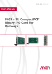
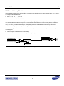
The external interrupt number (EXIn) doesn't have relation with the wakeup source number (WSRCx). WSRC0
can have something among 16 external interrupts (from EXI0 to EXI15). And the interrupt of WSRCx becomes
WIx. In other words, the interrupt of WSRC0 (WSRC1/WSRC2/WSRC3/WSRC4/WSRC5/WSRC6/WSRC7) is WI0
(WI1/WI2/WI3/WI4/WI5/WI6/WI7).
EXI0
WSRC0
WI0
WSRC1
WI1
WSRC2
WI2
WSRC3
WI3
WSRC4
WI4
WSRC5
WI5
WSRC6
WI6
WSRC7
WI7
EXI1
EXI2
EXI3
EXI4
EXI5
EXI6
EXI7
EXI8
EXI9
EXI10
EXI11
EXI12
EXI13
EXI14
EXI15
Figure 1
Mapping between WSRCx (WIx) and EXIn
14
S3FN41F_Application Note_REV1.00
2 External Interrupt
2.3 External Interrupt Enable
If the mapping between EXIn and WSCRx is completed, let's think WIx as the same name of EXIn. WIx is one-toon correspondent with WSCRx.
EXIn: n = 0, 1, 2, … , 14, or 15
WSCRx, WIx: x = 0, 1, 2, 3, 4, 5, 6, or 7
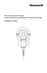
You can enable or disable WIx interrupt (EXIn interrupt) using CM_WIMSCR register. To use the interrupt, also
you should enable the interrupt vector for the corresponding interrupt source. WI0 interrupt has the separated
vector (WSI0, the IRQ number is 6.) Other WIx interrupts have the common shared vector (WSIx, the IRQ number
is 31). So when you enable WI0 interrupt, WSI0 (IRQ6) should be enabled. Other WIx interrupts should be
enabled with WSIx (IRQ31) interrupt vector together.
See the below figures. That shows the relation between registers for the control interrupt and each interrupt vector
control register.
WI0 Interrupt WSI0 Interrupt Vector (IRQ6)
WI1/2/3/4/5/6/7 Interrupt WSIx Interrupt Vector (IRQ31)
NVIC_ISER/ICER
CM_WIMSCR.WI0
External Interrupt Trigger
CM_WMISR.WI0
CM_WRISR.WI0
NVIC_ISPR/ICPR
clear
CM_WICR.WI0
Figure 2
WI0 Interrupt and WSI0 Vector
15
IRQ6
WSI0
S3FN41F_Application Note_REV1.00
CM_WIMSCR.WI1
External Interrupt Trigger
2 External Interrupt
CM_WMISR.WI1
CM_WRISR.WI1
clear
CM_WICR.WI1
CM_WIMSCR.WI2
External Interrupt Trigger
CM_WMISR.WI2
CM_WRISR.WI2
clear
CM_WICR.WI2
CM_WIMSCR.WI3
External Interrupt Trigger
CM_WMISR.WI3
CM_WRISR.WI3
clear
CM_WICR.WI3
NVIC_ISER/ICER
CM_WIMSCR.WI4
External Interrupt Trigger
OR
CM_WMISR.WI4
CM_WRISR.WI4
NVIC_ISPR/ICPR
clear
CM_WICR.WI4
CM_WIMSCR.WI5
External Interrupt Trigger
CM_WMISR.WI5
CM_WRISR.WI5
clear
CM_WICR.WI5
CM_WIMSCR.WI6
External Interrupt Trigger
CM_WMISR.WI6
CM_WRISR.WI6
clear
CM_WICR.WI6
CM_WIMSCR.WI7
External Interrupt Trigger
CM_WMISR.WI7
CM_WRISR.WI7
clear
CM_WICR.WI7
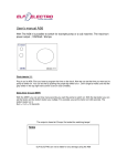
Figure 3
WIx Interrupt and WSIx Vector
16
IRQ31
WSIx
S3FN41F_Application Note_REV1.00
2 External Interrupt
2.4 External Interrupt Handler
In external interrupt handler, you should clear the pending interrupt as like other interrupt handler. It can be done
by writing "1" into each interrupt bit of CM_WICR register. Also additional operation can be added by your system
application. The below table is one of the simple example.
Example 1
External Interrupt Handler
void CSP_WSI0Handler(void)
{
CSP_CM_SET_WICR (CM0, CM_WI0); /* Clear WI0 interrupt pending bit */
}
void CSP_WSIxHandler(void)
{
isr_flag = CSP_CM_GET_WMISR (CM0);
if((isr_flag & CM_WI1)== CM_WI1)
CSP_CM_SET_WICR(CM0, CM_WI1);
if((isr_flag & CM_WI2)== CM_WI2)
CSP_CM_SET_WICR(CM0, CM_WI2);
if((isr_flag & CM_WI3)== CM_WI3)
CSP_CM_SET_WICR(CM0, CM_WI3);
if((isr_flag & CM_WI4)== CM_WI4)
CSP_CM_SET_WICR(CM0, CM_WI4);
if((isr_flag & CM_WI5)== CM_WI5)
CSP_CM_SET_WICR(CM0, CM_WI5);
if((isr_flag & CM_WI6)== CM_WI6)
CSP_CM_SET_WICR(CM0, CM_WI6);
if((isr_flag & CM_WI7)== CM_WI7)
CSP_CM_SET_WICR(CM0, CM_WI7);
}
17
S3FN41F_Application Note_REV1.00
2 External Interrupt
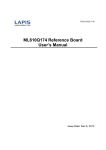
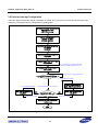
2.5 External Interrupt Configuration
The below figure includes the register information to control when you want to use the external interrupt. And it
shows the overall flow from the configuration to pending clear.
Generate interrupt handler (ISR)
CSP_WSI0Handler
CSP_WSIxHandler
EXI pin configuration
IOCONF_MLR0/1
IOCONF_MHR0/1
Configure EXI interrupt source
CM_WCR0
CM_WCR1
Clear status bit (RISR, MISR)
CM_WICR
Enable target interrupt … (a)
CM_WIMSCR
It is possible to enable interrupt
(a) after enable IRQ vector (b).
Enable IRQ Vector …(b)
(NVIC_ISER)
Waiting for the external event.
Triggered external signal?
Jump WSIx Handler
automaticllay
Jump WSI0 Handler
automatically
Clear interrupt pending
CM_WICR
YES
Check pending source
CM_WMISR/CM_WRISR
The external event occurred.
CM_WIMSR.WI0 ==1
Return from ISR
NO
Clear interrupt pending
CM_WICR
Return from ISR
Execute the next instruction
continuously
END
Figure 4
Flow Chart for External Interrupt
18
S3FN41F_Application Note_REV1.00
2 External Interrupt
You can find the detailed description about each register from S3FN41F user's manual and ARM's manual.
Refer to chapter 14. I/O Configuration of S3FN41F user's manual
IOCONF_MLR0/1
IOCONF_MHR0/1
Refer to chapter 6. Clock & Power Manager of S3FN41F user's manual
CM_WCR0/1
CM_WIMSCR
CM_WICR
CM_WMISR
CM_WRISR
Refer to chapter ARMv6-M Architecture Reference Manual
NVIC_ISER
19
S3FN41F_Application Note_REV1.00
3
3 Example
Example
This section provides the external interrupt example using the S3FN41F evaluation board.
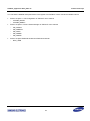
3.1 Hardware
This example needs POWER, H/L Gen, LED, and Wakeup Source parts basically. Also if you want to watch the
display through UART, include USART2 part.
Figure 5
Block Diagram of S3FN41F Evaluation Board
20
S3FN41F_Application Note_REV1.00
3 Example
Each part should be controlled according to the following guide.
H/L Gen part
Wakeup Source part
Connect between WAKEUP and EXI0 in J61
Connect between WAKEUP and EXI10 in J61
4 x LED part
Connect between WAKEUP and L in J62
Connect J63 jumpers
USART2
Connect between P1.8_RX and UART in J53
Connect between P1.9_TX and UART in J54
Connect to PC comport through P3 (Baud-rate 19200bps)
Figure 6
Board Condition for Example
21
S3FN41F_Application Note_REV1.00
3 Example
3.2 Software
This example uses EXI0 and EXI10 pin. EXI10 interrupt is remapped to WI0 interrupt by writing EXI10 value to
WSRC0. EXI0 interrupt is remapped to WI1 interrupt by writing EXI0 value to WSRC1. Simply it can be described
as like this.
P1.22 EXI10 WSRC0 WI0 WSI0
P0.15 EXI0 WSRC1 WI1 WSIx
Example 2
I/O Configuration Function
void CSP_IOFunctionConfigure(eGROUPy iogroup,U8_T port, U8_T function)
{
U32_T temp = 0;
U8_T new_port =0;
if(iogroup == GROUP0 )
{
if(port <16)
{
temp = CSP_IOCONF_GET_MLR0(IOCONF0) & (~(IOCONF_FSEL_MASK <<(2*port)));
CSP_IOCONF_SET_MLR0(IOCONF0, temp|(function << (2*port )));
}
else
{
new_port= port-16;
temp = CSP_IOCONF_GET_MHR0(IOCONF0) & (~(IOCONF_FSEL_MASK <<(2*new_port)));
CSP_IOCONF_SET_MHR0(IOCONF0, temp|(function << (2* new_port )));
}
}
if(iogroup == GROUP1 )
{
if(port <16)
{
temp = CSP_IOCONF_GET_MLR1(IOCONF0) & (~(IOCONF_FSEL_MASK <<(2*port)));
CSP_IOCONF_SET_MLR1(IOCONF0, temp|(function << (2*port )));
}
else
{
new_port= port-16;
temp = CSP_IOCONF_GET_MHR1(IOCONF0) & (~(IOCONF_FSEL_MASK <<(2*new_port)));
CSP_IOCONF_SET_MHR1(IOCONF0, temp|(function << (2* new_port )));
}
}
}
22
S3FN41F_Application Note_REV1.00
Example 3
3 Example
EXI10 (WI0) and EXI0 (WI1) Interrupt Configuration
/* External interrupt configuration - EXI10 */
CSP_IOFunctionConfigure(GROUP1, 22, IOCONF_F1);
//P1.22 is defined as EXI10 (Function 1)
source0 = CM_WSRC0(CM_WSRC_EXI0)|CM_EDGE0|CM_WEN0;
//WSRC0 setting value
CSP_CM_SET_WCR0(CM0, source0);
//WI0 interrupt is configured as EXI10 interrupt
CSP_CM_SET_WICR(CM0,CM_WI0);
//Clear WI0 interrupt status
CSP_CM_SET_WIMSCR(CM0,CM_WI0);
//Enable WI0 interrupt
CSP_NVIC_SET_ISER(NVIC0, 0, NVIC_INT6);
//Enable WSI0 interrupt vector for WI0 interrupt
/* External interrupt configuration - EXI0 */
CSP_IOFunctionConfigure(GROUP0, 15, IOCONF_F1);
//P0.15 is defined as EXI0 (Function 1)
source1 = CM_WSRC1(CM_WSRC_EXI10)|CM_EDGE1|CM_WEN1;
//WSRC1 setting value
CSP_CM_SET_WCR0(CM0, CSP_CM_GET_WCR0(CM0)|source1);
//WI1 interrupt is configured as EXI0 interrupt.
CSP_CM_SET_WICR(CM0,CM_WI1);
//Clear WI1 interrupt status
CSP_CM_SET_WIMSCR(CM0,CSP_CM_GET_WIMSCR(CM0)|CM_WI1); //Enable WI1 interrupt
CSP_NVIC_SET_ISER(NVIC0, 0, NVIC_INT31);
//Enable WSIx interrupt vector for WI1 interrupt
If the external interrupt configuration is completed, the external interrupt can occur by the signal to be asserted
through EXI0 or EXI10 pin. In this example, WI1 and WI0 interrupts occur at the same time because event signal
triggered by SW17 is connected with both EXI0 and EXI10. But the WI0 interrupt handler will be served first. The
reason is that the default priority of WI0 interrupt vector (WSI0 = IRQ6) is higher than WI1 interrupt vector (WSIx =
IRQ31).
Let's execute this example. After reset, the configuration is done. If that is completed, you can see the message to
be displayed until (a). At this time, four LEDs turn on. If there is no SW17's push, there will be no change any
more. Because the microcontroller is waiting for the external interrupt trigger signal. Let's push the switch button of
SW17. You can see the result to be done by the external interrupt handler. That is (b) and (c). These are sent
while microcontroller serves each interrupt handler operation. If you see all message as like the below, this
example execution is finished. To notify the end, all LEDs will blink.
Figure 7
The Execution Message Through UART
23