1
Freescale Semiconductor
Application Note
Document Number: AN4064
Rev. 0, 03/2010
Utilizing 36-Bit Physical Addressing
in U-Boot and Linux
Many of Freescale Semiconductor’s PowerPC cores,
including both the e600 and e500v2 processor families and
their derivatives, provide support for 36-bit physical
addressing. This support enables the processor core to access
64 Gbytes of physical address space, increasing the amount
of memory and device address space supported by the
system. This is increasingly necessary as more and more
embedded systems require large amounts of memory.
This document explains how to enable and utilize 36-bit
physical addressing. In particular, it describes the 36-bit
capabilities of the e600 and e500v2, and later processor
families. It also details how U-Boot and Linux have been
modified to support this feature and explains the limitations
of this support.
Note that the U-Boot and Linux descriptions specified in the
document only describe the operation of the software as
implemented for platforms based on the e600 and e500
processor families.
© Freescale Semiconductor, Inc., 2010. All rights reserved.
1.
2.
3.
4.
5.
Contents
Understanding Addressing . . . . . . . . . . . . . . . . . . . . . 2
Hardware Support Overview . . . . . . . . . . . . . . . . . . . 4
Utilizing 36-Bit Physical Addressing in U-Boot . . . . 7
36-Bit Addressing in the Device Tree . . . . . . . . . . . 10
Enabling and Utilizing 36-Bit Addressing in Linux . 12
Understanding Addressing
1
Understanding Addressing
Addressing and memory management in a computer system is a difficult topic that is largely beyond the
scope of this document. This section explains some of the basic concepts that are essential to understand
in order to develop system-level software that utilizes 36-bit physical addressing.
1.1
Addressing Definitions
In order to understand 36-bit physical addressing support, it is first necessary to understand the different
types of addresses used by a PowerPC processor and how each address is used. The different address types
include the effective address, virtual address, and the physical (or real) address.
An effective address is the address that is used by a program to access storage. On a 32-bit processor, an
effective address is 32 bit. Thus, 32 bits worth of address space, or 4 Gbytes, is the maximum amount of
address space reachable at one time by a single user process on a 32-bit processor. An operating system
may further restrict this amount as described later in this document.
A virtual address, as defined by the PowerPC architecture, is an intermediate address that is generated by
the processor core during the address translation process. Whenever a program performs a storage access
operation (for example, loads and stores), the processor core’s Memory Management Unit, or MMU,
creates a larger virtual address by concatenating an implementation-dependent number of bits to the
effective address that represent the process context, along with some other information. This virtual
address is then used to translate the address into a physical address.
A physical (or real) address is the address obtained when the virtual address is translated by the MMU
using address mappings programmed by operating system software. The physical address is then sent on
to the memory subsystem, and is used to access memory and devices such as PCI. A physical address
corresponds to some physical resource in the system. Physical addresses are not generally visible to
software except where they are used by the operating system to set up virtual address mappings in the
MMU.
Note that the physical address may be larger than effective addresses, as is the case on 32-bit PowerPC
processors that support 36-bit physical addressing. The operating system manages the larger physical
space as described in Section 1.2, “Addressing in User Software,” and the increase in physical address size
is invisible to user processes.
For a detailed explanation of the PowerPC address translation process, refer to the user’s manual for the
specific processor family of interest. 85xx and 86xx processors have very different MMU
implementations, but the concepts are the same.
1.2
Addressing in User Software
User programs are generally unaware of the location or layout of physical memory in a computer system.
This would put a huge burden on the application programmer. Instead, it is the job of the operating system
to utilize the processor’s MMU hardware to provide a memory management scheme that hides the details
of physical memory from the user program. This allows the user program to see a flat, apparently
contiguous 32-bit address space.
Utilizing 36-Bit Physical Addressing in U-Boot and Linux, Rev. 0
2
Freescale Semiconductor
Understanding Addressing
In reality, though, the memory accessed by a user program may be scattered throughout physical memory,
and it may be located anywhere in the physical memory space. In the case of a system that supports 36-bit
physical addresses, the user program’s memory may exist, in all or in part, at physical addresses that are
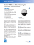
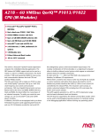
greater than 32 bits. As an example, the physical memory layout for a simplified 32-bit process on a system
with more than 4 Gbytes of memory may look like Figure 1.
0x00000000
0x00000000
0xFFFFFFFF
32-bit Process
Effective
Address Space
Physical
Memory
0xF_FFFFFFFF
(or top of memory,
whichever is smaller)
Figure 1. Process Memory Layout
The operating system constructs a table of effective to physical addresses for each process, and uses this
table to set up MMU mappings in the processor that allows the user process to see the memory as part of
its 32-bit effective address space, regardless of its actual physical location. Whenever a user program
performs a memory access, the 32-bit effective address is translated by the MMU to a 36-bit physical
address that is used to access the physical memory.
As physical (real) addresses are never used directly by a user program, and because the effective address
is limited to 32 bits, a user program can only ever access 32 bits, or 4 Gbytes, of the address space at one
time. Systems may place further limits on the amount of address space a user program can access, as
described below. Because user programs do not use physical addresses, no change to a user program is
required to run on a system with 36-bit physical addressing.
Note that even though individual processes have an effective address space that is limited to 32 bits, it is
still possible to make use of the large amounts of memory in a system. This is because most modern
Utilizing 36-Bit Physical Addressing in U-Boot and Linux, Rev. 0
Freescale Semiconductor
3
Hardware Support Overview
operating systems provide the ability to have multiple processes, each accessing 32 bits (or less, depending
on operating system constraints) of address space. Having multiple processes allows the large amounts of
memory supported by cores that implement 36-bit physical addressing support to be used.
2
Hardware Support Overview
Hardware support for 36-bit physical addressing consists of two main parts: PowerPC Core support and
SOC support. The following sections give an overview of the specific hardware capabilities for each of
which a system software programmer should be aware.
2.1
PowerPC Core Hardware Support
The MMU of PowerPC cores that support 36-bit physical addressing allows a 32-bit effective address to
be translated into a 36-bit physical address. In most cases, this simply means that the core data structures
that control the operation and programming of the MMU have been expanded to accommodate an
additional 4 bits of physical address. The system-level software-visible changes to each core are
highlighted below. Refer to the relevant core reference manual for the details on how these changes impact
address translation and how each is used.
For e600 cores, the changes include:
• The extended addressing enable (XAEN) bit in HID0, which enables the processor to use 36-bit
physical addresses. When this is disabled, the processor only uses 32 bits of physical address
• An additional 3 bits of physical address (HTABEXT) and an additional 4 bits of mask (HTMEXT)
in SDR1
• An additional 4 bits of real page number (RPN) in the lower BAT register, represented by the
BXPN and BX fields
• Support for an extended block size in the upper BAT register, represented by the XBL field
• An additional 4 bits of RPN in the hardware page table entry (PTE), represented by the XPN and
X fields
• An additional 4 bits of RPN in the translation lookaside buffer (TLB), represented by the XPN and
X fields
• An additional 4 bits of physical address in the PTELO register, represented by the XPN and X
fields. Note that this register is only used when a software page table walk is in effect. Most
operating systems utilize the processor’s hardware page table walk feature.
For e500v2 and later cores, the changes include:
• An additional 4 bits of RPN in the TLB entries
• An additional 4 bits of RPN for programming/reading the TLB entries, stored in MAS7
• The EN_MAS7_UPDATE bit in HID0, which enables MAS7 updates when a TLB read or search
instruction is executed
Utilizing 36-Bit Physical Addressing in U-Boot and Linux, Rev. 0
4
Freescale Semiconductor
Hardware Support Overview
2.2
System on a Chip (SOC) Details
In addition to the core support for 36-bit physical addressing, the SOC must also provide capabilities for
accessing devices in 36-bit physical space. The software-visible aspects of this support may include:
• Local access windows (LAWs) that support 36-bit physical addresses and specify the target
mapping for physical accesses.
• Address translation and mapping unit (ATMU) support for large physical addresses. Interfaces
such as PCI Express and serial RapidIO use inbound and outbound windows to translate addresses
between the local address space to the PCI Express or serial RapidIO address space.
• DDR controllers that are capable of dealing with more than 4 Gbytes of memory.
• Additional bits in the local bus controller (LBC) configuration registers to allow access to
larger-sized address spaces. The number of additional bits may be less than 4; for example, the
MPC8641 LBC supports 34 bits of address.
• Support for programming the configuration, control, and status base address register (CCSRBAR)
for 36-bit physical space.
2.3
PCI Express Address Translation
Some interfaces such as PCI Express and serial RapidIO provide address translation and mapping units
(ATMUs) to translate addresses between the internal platform address space and the interface’s private
address space. As mentioned above, the move to 36-bit physical addressing can impact the programming
of these ATMUs. In order to understand this, one must first fully understand how these ATMUs work, and
how they fit into the overall address translation scheme.
Consider the PCI Express ATMU as an example. The PCI Express controllers on parts such as the
MPC8572 and the MCP8641 provide a connection to the PCI Express bus to which various PCI devices
may be attached. These PCI Express controllers support both 32- and 64-bit PCI devices. The PCI Express
bus has its own 64-bit address space that is used by the devices on the PCI Express bus, and mappings
to/from this address space from/to the rest of the system are defined by the inbound and outbound ATMU
windows.
The inbound ATMU windows provide a translation mechanism for transactions issued from PCI space to
the internal platform, while outbound windows provide a mapping for transactions issued to PCI Express.
The outbound windows are typically set up to map the PCI Express MMIO space to allow incoming
transactions access to this space. Likewise, the inbound windows typically map the system memory to
allow outgoing PCI Express transactions to access memory. This means that the 64-bit PCI Express
address is split between outbound mappings for PCI Express memory-mapped IO (MMIO) and inbound
mappings for system memory.
Since all PCI devices are not capable of accessing all 64 bits of the PCI Express address space, anything
that needs to be reachable by all PCI devices must be mapped by software into the low 32 bits of the PCI
Express address space.
Utilizing 36-Bit Physical Addressing in U-Boot and Linux, Rev. 0
Freescale Semiconductor
5
Hardware Support Overview
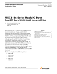
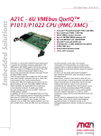
A typical 64-bit PCI Express address space layout is depicted in Figure 2.
0x00000000_00000000
System Memory
0x00000000_E0000000
PCI Express MMIO
0x00000000_FFFFFFFF
System Memory
0xFFFFFFFF_FFFFFFFF
Figure 2. Example PCI Express Address Map
In Figure 2, the first 3.5 Gbytes of the PCI Express address space from 0x00000000_00000000 to
0x00000000_DFFFFFFF is allocated to map system memory. The next 512 Mbytes from
0x00000000_E0000000 to 0x00000000_FFFFFFFF is dedicated to PCI Express MMIO. At this point, the
limit of the 32-bit PCI Express address space is reached, and any mapping beyond this point is not usable
by 32-bit PCI devices. More system memory can be mapped beyond 32-bit space, but it is only visible to
64-bit capable PCI devices, and an operating system may or may not support a hole in the PCI system
memory mapping (Linux does not as of version 2.6.31).
Using the example of PCI Express address map above, the inbound windows for the PCI Express controller
would be programmed to map the first 3.5 Gbytes of system memory from the PCI address space to its
physical address in the system (specified by the memory map for the board). For Linux and U-Boot, the
system memory is usually located at physical address 0, so the inbound windows would be programmed
to start at 0. Depending on the maximum window size supported, it may take more than one window to
map in the 3.5 Gbytes. The outbound windows are programmed such that the PCI Express MMIO, located
at 0x00000000_E0000000 on the PCI bus in this example, is mapped into the 36-bit physical space at the
location specified by the board’s memory map. In this example, that location would be 0xC_00000000.
In this example, because a maximum of 3.5 Gbytes of system memory is mapped into the PCI Express
address space, PCI devices cannot directly access system memory beyond the 3.5 Gbyte point. When
access above 3.5 Gbytes is required, the operating system software must intervene. For Linux, this
intervention is explained in Section 5.2, “SWIOTLB Bounce Buffering Support.”
Utilizing 36-Bit Physical Addressing in U-Boot and Linux, Rev. 0
6
Freescale Semiconductor
Utilizing 36-Bit Physical Addressing in U-Boot
2.4
Address Translation Examples
With all the different layers of address mappings and translations, it can be difficult to understand the full
path an access might take from the time a program accesses an effective address to the point where
hardware is accessed, particularly when looking at 36-bit physical addressing. This section provides a
couple of quick examples of different translation paths that might be used.
One of the simplest examples is how a user process accesses memory. The user process accesses a 32-bit
effective address. This address is then formed by the processor into a virtual address as described in
Section 1.2, “Addressing in User Software.” The processor matches this virtual address against the
MMU’s translation entries to produce a 36-bit physical address. The 36-bit address is then matched against
the LAW entries that point the access to the memory controller. The memory controller then uses the
address to access memory.
However, accessing the PCI MMIO space is slightly more complicated. As above, a 32-bit effective
address is used by software, which is again translated into a 36-bit physical address by the MMU. This
physical address is then matched against the LAWs to determine that the access should be processed by
the PCI Express controller. The PCI Express controller then uses the outbound ATMU entries to determine
what 64-bit address on the local PCI Express bus corresponds to the 36-bit physical address presented to
the interface. Finally, this 64-bit PCI Express address is used to access PCI Express MMIO space.
3
Utilizing 36-Bit Physical Addressing in U-Boot
The U-Boot boot loader is widely available for the various PowerPC processor families, and provides
support for utilizing 36-bit physical addressing starting with version v2009.06.
This section details the 36-bit memory map considerations and explains how U-Boot uses the MMU. It
also discusses how to build a 36-bit capable U-Boot.
3.1
Memory Map
Each board configuration supported by U-Boot must specify a memory map that details the allocation of
the 36-bit physical address space. On most of the 32-bit PowerPC configurations, U-Boot utilizes
one-to-one mappings for the address space; that is, the effective address and the physical address are
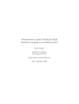
always equal. As an example, consider the 32-bit memory map for the MPC8641 HPCN platform with PCI
enabled as shown in Table 1.
Table 1. 32-bit MPC8641 HPCN Memory Map
Effective
Physical
Device
Size
0x0000_0000
0x0000_0000
DDR memory
0x8000_0000
0x8000_0000
PCI1/PCI Express 1 MEM
512 Mbyte
0xA000_0000
0xA000_0000
PCI2/PCI Express 2 MEM
512 Mbyte
0xFFE0_0000
0xFFE0_0000
CCSR
1 Mbyte
0xFFDF_0000
0xFFDF_0000
PIXIS
8 Kbyte
0xFFDF_8000
0xFFDF_8000
Compact Flash
8 Kbyte
2 Gbyte
Utilizing 36-Bit Physical Addressing in U-Boot and Linux, Rev. 0
Freescale Semiconductor
7
Utilizing 36-Bit Physical Addressing in U-Boot
Table 1. 32-bit MPC8641 HPCN Memory Map (continued)
Effective
Physical
Device
Size
0xF840_0000
0xF840_0000
Stack space
32 Kbyte
0xFFC0_0000
0xFFC0_0000
PCI1/PCI Express 1 IO
64 Kbyte
0xFFC1_0000
0xFFC1_0000
PCI2/PCI Express 2 IO
64 Kbyte
0xEF80_0000
0xEF80_8000
Flash
8 Mbyte
On switching to a 36-bit physical addressing, this one-to-one mapping is no longer possible if the devices
above 32 bits need to be placed because the physical address space is larger than the effective address
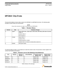
space. Therefore, a new memory map for the board must be established. Using MPC8641 HPCN as an
example, the new memory map is shown in Table 2.
Table 2. 36-bit MPC8641 HPCN Memory Map
Effective
Physical
Device
Size
0x0000_0000
0x0_0000_0000
DDR memory
0x8000_0000
0xC_0000_0000
PCI1/PCI Express1 MEM
512 Mbyte
0xA000_0000
0xC_2000_0000
PCI2/PCI Express2 MEM
512 Mbyte
0xFFE0_0000
0xF_FFE0_0000
CCSR
1 Mbyte
0xFFDF_0000
0xF_FFDF_0000
PIXIS
8 Kbyte
0xFFDF_8000
0xF_FFDF_8000
Compact Flash
8 Kbyte
0xF840_0000
0xF_F840_0000
Stack space
32 Kbyte
0xFFC0_0000
0xF_FFC0_0000
PCI1/PCI Express 1 IO
64 Kbyte
0xFFC1_0000
0xF_FFC1_0000
PCI2/PCI Express 2 IO
64 Kbyte
0xEF80_0000
0xF_EF80_8000
Flash
8 Mbyte
2 Gbyte
The effective addresses remain the same as for the 32-bit implementation, but with the exception of
memory, the devices are all located at physical addresses above 32 bits. This physical memory placement
is intentional, and allows for large amounts of memory to be present and contiguous starting at 0. This
memory placement is more important to Linux than U-Boot; U-Boot is only able to access as much
memory as it has effective address space allocated for memory, but it sets things up correctly so that Linux
may make use of larger amounts of memory once it begins to use paging.
Note that many devices power up at a default location that differs from the desired final location. These
devices are carefully moved into high physical address space during the U-Boot initialization process in
order to establish this memory map.
3.2
MMU Setup
U-Boot does not provide sophisticated memory management features like demand paging. Instead, U-Boot
utilizes fixed mappings for any memory or devices it needs to access. These fixed MMU mappings are
Utilizing 36-Bit Physical Addressing in U-Boot and Linux, Rev. 0
8
Freescale Semiconductor
Utilizing 36-Bit Physical Addressing in U-Boot
created using the BAT registers on e600 family processors, or using the variable-sized TLB array (TLB1)
on e500 family processors. Devices and memory are mapped into the effective address space according to
the memory map for the board as described in Section 3.1, “Memory Map.” These mappings are for
U-Boot’s use only; Linux reprograms the MMU after it takes over the processor.
3.3
U-Boot Initialization
One of the most important jobs of U-Boot is to set up some of the hardware features that are used by an
operating system. In particular, U-Boot must set up the local access windows (LAWs), the LBC, and the
PCI or serial RapidIO (SRIO) ATMU to match the memory map that has been specified for a board.
Without this setup, devices are inaccessible.
The LAWs contain information that specifies the target device for ranges of addresses. The effective
address used by a process is translated into a physical address by the processor’s MMU. The physical
address goes out on the bus and is matched against the LAWs to determine which device should respond
to the transaction. These windows must be correctly programmed with the physical address range assigned
to each device in the memory map.
The PCI and SRIO interfaces provide an ATMU. One of the functions of the ATMU is to translate between
external addresses and addresses within the local PCI or SRIO address space. These mappings must also
be changed to support the new 36-bit physical memory map.
Many of th Freescale Semiconductor’s SOCs provide an LBC that must also be configured for 36-bit
addressing. Unfortunately, the LBC does not usually support the full 36 bits of physical address space
(refer to the SOC documentation for specific information about the LBC on a particular chip). Therefore,
the LBC should be configured for as many address bits as it supports. The lack of a full 36 bits of address
at the LBC is not generally an issue, because the LBC does not require large amounts of address space.
Linux does not modify the LAW and LBC setup, so it is important that these are correctly initialized by
U-Boot. The PCI and SRIO ATMU settings are changed by Linux at boot time.
3.4
Building a 36-bit U-Boot
Each board that supports 36-bit physical addressing provides a make configuration option that
automatically builds a U-Boot with a 36-bit memory map and support for 36-bit physical addressing. For
the Freescale boards that have both a 32- and 36-bit configuration, the configuration name is same as the
32-bit configuration version, but with “_36BIT_” added. As an example, to configure a 32-bit U-Boot for
the MPC8641 HPCN, the command is make MPC8641HPCN_config. To make a 36-bit U-Boot, the command
becomes make MPC8641HPCN_36BIT_config. Note that some platforms may always enable 36-bit support;
for those platforms, the standard <boardname>_config file enables this option.
The underlying configuration option that enables large physical addressing is CONFIG_PHYS_64BIT. To
add a 36-bit make configuration option for a board with existing 32-bit support, commands should be
added to U-Boot’s global Makefile that set this configuration option, and then complete the board
configuration using the standard configuration file for the board. The actual configuration file should never
be duplicated to accomplish this.
Utilizing 36-Bit Physical Addressing in U-Boot and Linux, Rev. 0
Freescale Semiconductor
9
36-Bit Addressing in the Device Tree
3.5
U-Boot Memory Usage Limitations
As the effective address space is still only 32 bits and U-Boot does not demand paging, in many cases, all
the memory in a system cannot be mapped by U-Boot. The specific limitation for a particular platform can
be determined by looking at the fixed MMU mapping the platform sets up to map memory (through a BAT
register or variable-size TLB array entry). The implication of this limitation is that it is not possible to
access the portion of the memory that is not mapped, and it is not possible to do a memory test on the entire
memory. However, a 36-bit-enabled U-Boot correctly initializes the DDR controller and reports the correct
memory size to Linux, so that Linux is capable of using all of the memory.
4
36-Bit Addressing in the Device Tree
In order to utilize the 36-bit support in Linux, each platform must provide a 36-bit device tree (.dts file)
that describes the various devices in the system and how they are mapped. Since there are numerous
quantities in the device tree that represent CPU physical addresses and sizes of large areas, the .dts file
must be updated now that these quantities are larger. This section details some of these changes and
provide some examples.
For more information about:
• the device tree as used by Linux, refer to documentation/powerpc/booting-without-of.txt in the
Linux source tree.
• the device tree and node definitions, see the URL for embedded Power Architecture® platform
requirements (ePAPR) at http://www.power.org/resources/downloads.
4.1
#address-cells and #size-cells
Each device tree provides a top-level bus #address-cells and #size-cells that describe the format of an
address and is applied to the direct children of the top-level bus. This value represents the number of 32-bit
quantities, or “cells”, that are required to represent an address and to indicate the size of address regions.
Many 32-bit device trees define #address-cells and #size-cells to be 1; however, for a 36-bit physical
configuration, these must be changed to 2 to accommodate the additional address bits and larger supported
sizes.
Generally, only the top-level #address-cells and #size-cells in a .dts file must be updated to support 36-bit
addressing – lower-level addresses and sizes specify quantities within the bus, so unless a bus requires
more than 4 Gbytes of address space, those quantities need not change.
Note that some 32-bit device trees are already using a “2” value – in this case the extra bits are just set to
0. This makes it easier to look at the differences between a 32- and 36-bit device trees and can reduce code
maintenance. This is now the preferred method for specifying 32-bit device trees.
4.2
reg Property
The format of the reg property varies depending on the parent node, but in many cases, the reg property
consists of a physical address and a size. The size of these values is determined by #address-cells and
#size-cells as explained above. Therefore, any node that is impacted by a #address-cells and #size-cells
Utilizing 36-Bit Physical Addressing in U-Boot and Linux, Rev. 0
10
Freescale Semiconductor
36-Bit Addressing in the Device Tree
change and which has a reg property that contains a physical address also requires a change to the reg
property. As an example, consider this change to the reg property of the MPC8641HPCN pci0 node:
reg = <0xffe08000 0x1000>;
becomes
reg = <0x0f 0xffe08000 0x0 0x1000>;
4.3
Unit Addresses
Each node in the device tree has a unit name, which is a unique identifier for the node. As part of this unit
name, many nodes specify a unit address for the device they represent. The unit address is the numerical
portion of the unit name which follows the “@” character. The unit address contains the address of the first
reg property of the device. For example:
pci0: pcie@ffe08000 {
in the 32-bit .dts for the MPC8641 HPCN becomes
pci0: pcie@fffe08000 {
when switching to a 36-bit memory map.
4.4
Ranges Property
The ranges property is used to translate addresses into the parent bus address. A typical ranges property
consists of:
bus address, parent bus address, size
The format of the bus address and parent bus address varies by device and parent bus. If either of those
quantities has become larger as the result of the conversion to 36-bit physical addressing, then these values
must be updated. An example of this is the PCI node on the MPC8641 HPCN. The bus address format for
the node does not change on going to 36-bit physical addressing, but the parent bus address represents a
CPU physical address that must now be expanded to hold the additional address bits. Thus, given the
memory map listed earlier, and adding support for the larger, different CPU physical addresses,
ranges = <0x02000000 0x0 0x80000000 0x80000000 0x0 0x20000000
0x01000000 0x0 0x00000000 0xFFC00000 0x0 0x00010000>;
becomes
ranges = <0x02000000 0x0 0x80000000 0x0C 0x00000000 0x0 0x20000000
0x01000000 0x0 0x00000000 0x0F 0xFFC00000 0x0 0x00010000>;
In this example, the bus address consists of three cells (0x02000000 0x0 0x80000000) that are unmodified.
The parent bus address, which is 0x80000000, in the example, is increased in size by one cell and changed
to accommodate the new physical address space layout and becomes 0x0C 0x00000000. The size field,
which was already two cells, remains unchanged.
Utilizing 36-Bit Physical Addressing in U-Boot and Linux, Rev. 0
Freescale Semiconductor
11
Enabling and Utilizing 36-Bit Addressing in Linux
5
Enabling and Utilizing 36-Bit Addressing in Linux
The Linux support for 36-bit physical addressing is available as of version 2.6.31 and consists of 4
components. These components are:
• Core Kernel MMU Modifications
• SWIOTLB Bounce Buffering Support
• Platform-specific 36-bit Support
• Device Driver Changes
This section explains each of these components, and, for the platform-specific and device driver sections,
gives some hints about how to enable new platforms and devices. It describes how to build a Linux kernel
with full 36-bit support enabled, and also explains Linux limits on process size. In addition, it briefly
discusses the performance implications of 36-bit physical addressing support.
5.1
Core Kernel MMU Modifications
Since it is the job of the Linux memory management code to allocate and track physical addresses, this
code must be updated to understand larger physical addresses. In general, this means that the kernel data
structures that represent effective-to-real translations must be increased in size to accommodate the
increased number of address bits. The kernel must also deal with the fact that it is possible that there is
more memory in the system than many of the devices can access for DMA operations. The kernel provides
SWIOTLB bounce buffering support to allow the affected devices to operate correctly.
5.2
SWIOTLB Bounce Buffering Support
Many devices that have DMA capability do not have the ability to address the entire 36-bit physical
address space. For example, many PCI devices only support 32 bits of address. This means that these
devices cannot directly DMA to the entire address space. To deal with this problem, the kernel provides
DMA bounce buffering capability known as SWIOTLB.
The data structure in Linux that represents a device contains a list of pointers to a set of DMA operations.
During boot, the kernel looks at the properties of the device and at how much memory the system has, and
decides if a device cannot address all of memory for DMA transfers. If it is determined that a device cannot
access all of memory, then the DMA operations for the device are set to point to the SWIOTLB
implementation instead of pointing to the normal direct DMA operations.
The concept of the SWIOTLB bounce buffering code is simple. Whenever a DMA is attempted to or from
an address that is not directly accessible by a device, the kernel provides a temporary buffer for the device
to use. All operations occur to that temporary buffer. Data is copied to or from the original DMA location
by the kernel as needed. Depending on the direction of the DMA operation (DMA_TO_DEVICE,
DMA_FROM_DEVICE, DMA_BIDIRECTIONAL), data may be written when a page is mapped or
unmapped (or both, for DMA_BIDIRECTIONAL). Data is also read from or written to the original DMA
location whenever any of the DMA synchronization operations are performed.
The address boundary at which a device must utilize bounce buffering is device-dependent. For simple
platform devices, the bounce buffering point is usually the address width of the device. That is, 32-bit
devices must bounce buffer accesses that require more than 32 bits to address. However, for some devices,
Utilizing 36-Bit Physical Addressing in U-Boot and Linux, Rev. 0
12
Freescale Semiconductor
Enabling and Utilizing 36-Bit Addressing in Linux
determining the point at which a device must begin to use the SWIOTLB facilities is slightly more
complicated, and a bus or controller may place additional limits on the addresses that devices can directly
access.
For example, as PCI Express controllers have their own internal address space (as discussed in Section 2.3,
“PCI Express Address Translation”) and part of this address space is for PCI Express MMIO, the
maximum address that can be directly accessed is reduced. Using the example, PCI Express address map
that is 512 Mbytes, is reserved for the MMIO; so, 3.5 Gbytes is the maximum address directly addressable
by 32-bit PCI devices. Accesses above this point must bounce buffer. The Linux kernel looks at the size
of the PCI controller’s windows and use this information to figure out when bounce buffering must occur.
NOTE
There is a kernel limitation in version 2.6.31 that causes 64-bit PCI devices
to bounce buffer as if they were only 32-bit capable. This will be addressed
in a future version of Linux.
5.3
Platform-Specific 36-Bit Support
Because the bulk of the kernel support for 36-bit is either completely generic code, or PowerPC
architecture code, enabling an existing platform to support 36-bit physical addressing is relatively simple.
The platform code must be changed in order to allow proper setup of DMA operations and to enable the
SWIOTLB bounce buffering support for the platform as follows:
• Add select SWIOTLB to the platform in arch/powerpc/platform/<platform family>/Kconfig
• Add code to the architecture setup function for the platform to change the default set of PCI DMA
operations to use the SWIOTLB versions if the PCI window setup and the amount of memory in
the system warrant it.
• Register the SWIOTLB bus notifier, which enables proper setup of the DMA API function pointers
for platform devices.
The following commits in the public Linux tree can be utilized as reference examples:
• powerpc/85xx: Add SWIOTLB support to FSL boards located at
http://git.kernel.org/?p=linux/kernel/git/torvalds/linux-2.6.git;a=commit;h=152d0182822e871a3f
e1f6d97949d83fad950e26.
• powerpc: Add 86xx support for SWIOTLB located at
http://git.kernel.org/?p=linux/kernel/git/torvalds/linux-2.6.git;a=commit;h=5cef379b34ffcd96567
066ddc1012bd40e6e7675.
5.4
Device Driver Changes
Correctly written Linux device drivers should require no modifications to work in a 36-bit physical
configuration. Unfortunately, correctly written device drivers are not the norm. There are three key
problems that should be looked for when making a driver 36-bit compliant:
• Assumption of 32-bit values for DMA addresses and physical addresses
• Non-adherence to the DMA API
• Passing incorrect/NULL dev pointer to the DMA API functions
Utilizing 36-Bit Physical Addressing in U-Boot and Linux, Rev. 0
Freescale Semiconductor
13
Enabling and Utilizing 36-Bit Addressing in Linux
Device drivers often require knowledge of the physical address of areas in system memory. Drivers for
devices that support direct memory access also use a type of address known as a DMA address to represent
the device’s view of the address of a location in system memory. The DMA address for a region is often
the same as the physical address, but may differ by a simple offset or other mechanism depending on the
device.
On a system that utilizes 36-bit physical addresses and has more than 4 Gbytes of system memory, a driver
must represent DMA addresses and physical addresses as 36-bit quantities. However, many driver writers
make the assumption that DMA addresses and physical addresses are always 32 bits and can be
represented by unsigned int or unsigned long data types. Use of these data types causes the driver to fail
any time an access is to 36-bit space, since there are not enough bits in these data types to contain the
entire address.
The Linux kernel hides possible variations in DMA and physical address size by providing the
dma_addr_t and phys_addr_t data types. These data types are correctly sized based on the kernel
configuration and should be used whenever a DMA address or physical address must be represented.
These types should also be used for mask quantities and for temporary variables that hold the result of
operations on DMA and physical addresses.
Note that aside from the portions of driver code that require direct knowledge of DMA addresses and
physical addresses (which, for example, may include device setup code, ioremap(), and DMA API calls),
a driver uses 32-bit effective addresses that are automatically translated into 36-bit physical addresses
using the processor’s MMU address translation tables. In this case, the driver behaves like any other piece
of code that uses effective addresses, and no other changes are required since this type of code has no
visibility into the physical location of system memory buffers.
The second common problem is finding that device drivers do not conform to the DMA API, as
documented in the Linux kernel tree in Documentation/DMA-API.txt. The DMA API specifies that for
every DMA map operation, there should be a corresponding unmap operation. In addition, it requires that
DMA sync operations should be utilized whenever the driver requires data from the device to be seen by
the CPU, and vice-versa. Following the DMA API is important because the SWIOTLB bounce-buffering
technique relies on this API – if it not followed, data can be lost or delayed, since there may be an
intermediate copy of the data that has to be synchronized before it is seen.
Another common driver issue is passing incorrect arguments to the DMA API functions. Older kernels did
not always use the dev pointer that is often passed into these functions, and many device drivers pass
NULL or an incorrect value in this field. The kernel has been modified to warn in the NULL case, but
drivers that pass incorrect pointers may see more subtle symptoms such as timeouts and dropped data.
5.5
32-Bit Process Size Limits in PowerPC Linux
User processes are limited to a 32-bit effective address space, which would imply that the maximum size
of a user process is 4 Gbytes. However, PowerPC Linux further limits the amount of memory a single user
process can access because it splits the 32-bit effective address space into two chunks (note that Linux
implementations for other architectures may behave differently). The first chunk is used for private,
non-global mappings that are not visible to all process contexts. These types of translations allow multiple
processes to use the same effective addresses yet have process-specific translations in the MMU. This
works because the process context is part of the information that is concatenated with an effective address
Utilizing 36-Bit Physical Addressing in U-Boot and Linux, Rev. 0
14
Freescale Semiconductor
Enabling and Utilizing 36-Bit Addressing in Linux
to create a virtual address, which is matched against MMU translation entries to determine if an entry can
be used to translate an address. If the process context information does not match, the translation is not
used.
The second chunk of the effective address space is used for global mappings. A global mapping is a special
type of MMU translation entry that is valid in all contexts. With a global mapping, the translation entry
matches to all process contexts. Linux uses this global mapping to map in a large chunk of memory that
contains the operating system itself as well as free memory space. This mapping is protected from
unwanted accesses by user processes because the MMU translation for this region has user-mode access
disabled.
In general, on PowerPC systems, the global kernel mapping uses the highest 1 Gbytes of the effective
address space. This means that user processes are limited to 3 Gbytes in size. Therefore, a process may not
access more than 3 Gbytes of memory at one time. If an application requires more than 3 Gbytes, it must
either be broken up into multiple processes, or it must implement its own memory management scheme to
map memory in and out of the process address space as needed, such that no more than 3 Gbytes of
memory is mapped at any particular time.
A detailed explanation of why Linux and many other operating systems require this type of global mapping
for the kernel is beyond the scope of this paper. The important thing to understand is that the size of a single
process is limited to 3 Gbytes. It is possible to change certain kernel parameters and rebuild the kernel to
allow for a larger process size. Although there may be some circumstances in which this is helpful, it is
not generally recommended.
While it is true that individual processes are limited to 3 Gbytes in size under Linux, having 36-bit physical
addressing allows more memory to exist in the system, which allows multiple large processes to exist at
once without swapping to disk. This greatly improves overall system performance because disk accesses
are much slower than accesses to system memory.
5.6
The ioremap() Function
The ioremap() function in Linux is used to map physical addresses into the kernel virtual address space.
Device drivers commonly use ioremap()to map in a physical range of device memory. The ioremap()
call continues to function exactly as it did before the introduction of 36-bit physical addressing, except that
the physical address passed into the function can be in 36-bit space, because the phys_addr_t data type
used to pass the physical address to ioremap()accommodates the larger data type. The ioremap()call
returns a 32-bit virtual address that the driver uses to access the area normally.
Note that the limits on how much address space a driver can ioremap()are no different than with a Linux
kernel that does not support 36-bit physical addressing. This is because the available kernel virtual address
space, not the physical address space, is the limiting factor for how much memory a device can ioremap().
The kernel usually reserves the top 1 Gbytes of the 32-bit virtual address space to use for kernel mappings.
Of this 1 Gbyte, 756 Mbytes is usually used for the kernel’s linear mapping of the first 758 Mbytes of
memory. This leaves 256 Mbytes available in the kernel’s virtual address space for dynamic mappings,
such as those created with vmalloc() and ioremap(). This means that the maximum amount of memory
a driver can ioremap()at one time is less than 256 Mbytes.
Utilizing 36-Bit Physical Addressing in U-Boot and Linux, Rev. 0
Freescale Semiconductor
15
Enabling and Utilizing 36-Bit Addressing in Linux
5.7
Building 36-Bit Linux Kernels
There are two configuration options that enable 36-bit physical support in Linux. They are
CONFIG_PHYS_64BIT and CONFIG_SWIOTLB.
CONFIG_PHYS_64BIT can be enabled by selecting “Large physical address support” in the top-level
“Processor Support” menu. This option enables the core support for 36-bit physical addressing and causes
phys_addr_t and dma_addr_t to be 64-bit wide.
CONFIG_SWIOTLB is required in systems with large amounts of memory and enables software bounce
buffering of DMA accesses. The exact amount of memory at which CONFIG_SWIOTLB is required
varies per platform. Since the kernel determines when bounce buffering is necessary and only bounces
those addresses that are above the bounce buffering point, kernel builds for platforms with 36-bit support
automatically enables this option.
In summary, to build a 36-bit enabled kernel:
• Run make <defconfig> for the platform
• Run make menuconfig, select “Processor Support”, and enable “Large physical address support”
• Run make
5.8
Performance Implications of 36-Bit Physical Addressing
The performance implication of running with a 36-bit enabled Linux kernel varies according to the board
configuration and the pattern of the DMA operations occurring in the system. In general, aside from a
slightly increased kernel size, there is often no measurable performance hit from simply enabling 36-bit
physical addressing in the kernel. All accesses (DMA and non-DMA) below the bounce buffering point
and non-DMA accesses above 32 bits incurs very little, if any performance penalty. Some types of
programs with large numbers of TLB misses may notice a small performance penalty due to the increased
size of the page table and the slight instruction count in the TLB miss handler.
DMA accesses, however, may see a significant performance hit, depending on the physical address of the
access. Whenever a DMA access must bounce buffer, it essentially requires all the DMA data to be copied
into or out of the kernel space when certain kinds of DMA accesses are performed. This incurs a significant
performance penalty. How often this occurs depends on the addresses to which a device must DMA.
Device drivers that allocate all of their memory in low memory never bounces buffer and does not see any
performance hit. However, in many cases, devices must perform DMA operations to memory that was not
allocated by the device driver itself, and it is possible for those memory locations to require bounce
buffering. There is no way to prevent these types of accesses.
Utilizing 36-Bit Physical Addressing in U-Boot and Linux, Rev. 0
16
Freescale Semiconductor
Enabling and Utilizing 36-Bit Addressing in Linux
THIS PAGE INTENTIONALLY LEFT BLANK
Utilizing 36-Bit Physical Addressing in U-Boot and Linux, Rev. 0
Freescale Semiconductor
17
How to Reach Us:
Home Page:
www.freescale.com
Web Support:
http://www.freescale.com/support
USA/Europe or Locations Not Listed:
Freescale Semiconductor, Inc.
Technical Information Center, EL516
2100 East Elliot Road
Tempe, Arizona 85284
1-800-521-6274 or
+1-480-768-2130
www.freescale.com/support
Europe, Middle East, and Africa:
Freescale Halbleiter Deutschland GmbH
Technical Information Center
Schatzbogen 7
81829 Muenchen, Germany
+44 1296 380 456 (English)
+46 8 52200080 (English)
+49 89 92103 559 (German)
+33 1 69 35 48 48 (French)
www.freescale.com/support
Information in this document is provided solely to enable system and software
implementers to use Freescale Semiconductor products. There are no express or
implied copyright licenses granted hereunder to design or fabricate any integrated
circuits or integrated circuits based on the information in this document.
Freescale Semiconductor reserves the right to make changes without further notice to
any products herein. Freescale Semiconductor makes no warranty, representation or
guarantee regarding the suitability of its products for any particular purpose, nor does
Freescale Semiconductor assume any liability arising out of the application or use of
any product or circuit, and specifically disclaims any and all liability, including without
limitation consequential or incidental damages. “Typical” parameters which may be
provided in Freescale Semiconductor data sheets and/or specifications can and do
vary in different applications and actual performance may vary over time. All operating
parameters, including “Typicals” must be validated for each customer application by
customer’s technical experts. Freescale Semiconductor does not convey any license
Japan:
Freescale Semiconductor Japan Ltd.
Headquarters
ARCO Tower 15F
1-8-1, Shimo-Meguro, Meguro-ku
Tokyo 153-0064
Japan
0120 191014 or
+81 3 5437 9125
support.japan@freescale.com
under its patent rights nor the rights of others. Freescale Semiconductor products are
Asia/Pacific:
Freescale Semiconductor China Ltd.
Exchange Building 23F
No. 118 Jianguo Road
Chaoyang District
Beijing 100022
China
+86 10 5879 8000
support.asia@freescale.com
claims, costs, damages, and expenses, and reasonable attorney fees arising out of,
For Literature Requests Only:
Freescale Semiconductor
Literature Distribution Center
1-800 441-2447 or
+1-303-675-2140
Fax: +1-303-675-2150
LDCForFreescaleSemiconductor
@hibbertgroup.com
Document Number: AN4064
Rev. 0
03/2010
not designed, intended, or authorized for use as components in systems intended for
surgical implant into the body, or other applications intended to support or sustain life,
or for any other application in which the failure of the Freescale Semiconductor product
could create a situation where personal injury or death may occur. Should Buyer
purchase or use Freescale Semiconductor products for any such unintended or
unauthorized application, Buyer shall indemnify and hold Freescale Semiconductor
and its officers, employees, subsidiaries, affiliates, and distributors harmless against all
directly or indirectly, any claim of personal injury or death associated with such
unintended or unauthorized use, even if such claim alleges that Freescale
Semiconductor was negligent regarding the design or manufacture of the part.
Registered trademarks: Freescale, the Freescale logo, CodeWarrior,
ColdFire, PowerQUICC, StarCore, and Symphony are trademarks of
Freescale Semiconductor, Inc. Reg. U.S. Pat. & Tm. Off.
Trademarks: CoreNet, QorIQ, QUICC Engine, and VortiQa are trademarks
of Freescale Semiconductor, Inc. All other product or service names are the
property of their respective owners. The Power Architecture and Power.org
word marks and the Power and Power.org logos and related marks are
trademarks and service marks licensed by Power.org.
© 2010 Freescale Semiconductor, Inc.