1
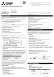
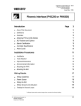
PR-9D12
1. Forew ord
All information and w arnings about 3 phase controlled reactive pow er controller, PR-9DXX*, are given in this User's Manual. Please
for your pow er netw ork's and your ow n safety, read this manual caref ully before commissioning the system. Please contact us for
unclear points.
RTR Energía S.L.
Albatros, 30
Pol. Ind. Pinto-Estación
28320 PINTO (Madrid) SPAIN
Tel.: 34 91 691 66 12
Fax: 34 91 691 22 57
e-mail:info@rtr.es
2. Warnings:
1- The connection, operation and parameter settings of device must be done by authorised technical service staff. Also, system
checks must be done by this person w hen necessary.
2- Since compensation is a complex process, subscribers are advised to keep the system tracking by contracted service staff.
3- Please do not open or do not let others open the device. There are no user serviceable parts inside.
4- Before making the connections to device's terminals, please be sure that there is no voltage across the cables or terminals. Also be
sure that the panel is de-energised.
5- Please do not use the device for purposes other then compensation.
6- Please fix the device to electric panel w ith apparatuses supplied.
7. Please press the buttons only by your fingers, do not press it w ith any other objects.
8- Before cleaning the device, please be sure that it is de-energised and use only dry tissue-paper to clean it. Water or any other
chemicals used for cleaning may harm the device.
9- Before installing the device, please be sure that the terminal connections are made exactly the same as in the connection diagram
and avoid any connection problems, such as loose connections or contact of diff erent cables.
10- For each capacitor bank on the compensation system, please prefer contactors w ith suitable discharge resistors considering the
bank pow er.
11- Please consider total currents draw n by the inductors of contactors w hile choosing the common contact line, line 'C', fuse value.
When contactors w ith high inductor currents are chosen, for protecting the contact outputs of the device, auxiliary relay must be
used.
* The statement PR-9DXX covers both 8 and 12 steps models of the device.
Ins tallation Ins tructions :
1. A hole w ith 140 mm x 140 mm must is needed on the panel for device installation
2. Remove the fixing apparatus before installing the device
3. Place the device in the prepared hole f rom the front side.
4. Use the fixing apparatus to f ix the device from the back side to the panel.
CAUTION:
Leave at least 50mm space betw een the back side of the device and the internal w all of the pannel for airing purpose
Wall
140 mm
Panel Hole Dimensions
140 mm
50 mm
3. Gene ral Inform ation
The most important properties of PR-9DXX that make it different from traditional type controllers are;
1- Measuring current and voltage samples from all 3 phases, calculating active and reactive pow ers and storing consumed energies,
2- Instead of reaching to target cosΦ value, compensating the system as much as close to real axis betw een the capacitive and
inductive bound values. (Bound values can be changed by the user w hen desired),
3- Automatic C/k calculation,
4- Automatic learning and monitoring of capacitor bank pow ers (capacitor bank pow ers can be set by the user w hen desired. Device
also detects any false setting and corrects it by its ow n as it operates),
5- Dynamically adjusting of normal region boundaries and capacitor sw itching on&off times w ith respect to consumed reactive/active
percentage,
6- Extending capacitor bank pow er life by storing sw itching on&of f times separately for each bank,
7- Automatic learning of current transformer polarities even if (k,l) is connected in reverse direction,
8- Calculating current reactive pow er value and directly sw itching on or off the most suitable group instead of sequential sw itching,
9- Making system tracking and fault detection easier w ith many hand alarms,
10- Compensation w ith respect to resultant pow er factor(Σ cosΦ) calculated as the vectorial sum of three phase pow ers.
1
PR-9D12
3.1 Ope rating Principles
When the device is energised, it checks first the voltage values. Then, it detects current transformer polarities even if connected in
reverse direction. The direction of system's reactive pow er is calculated through resultant reactive pow er and resultant pow er
factor. Compensation starts for pulling the system into 'normal region'. Device measures active, inductive (+Q) and capacitive (-Q)
pow ers for each phase and stores the consumed energies. After mathematical calculations, inductive and capacitive percentage
values of the system are calculated continuously and the system is kept under control.
Capacitor sw itching on&off times are calculated separately for each bank. When necessary, the appropriate bank is directly
sw itched if its time is up. Since the Sw itching Time Values and Normal Region Boundaries are related to consumed energies, they
change betw een the max and min values proportional to percentage energies. During the operation, every capacitor bank's pow er is
calculated w hen it is sw itched. Therefore, any change of the capacitor bank's pow er is detected and stored. Instead of sequential
sw itching of capacitors, the most suitable bank is directly sw itched. PR-9DXX contains 9 alarms from AL01 to AL09 and 1 alarm
relay output to w arn and inform the user. Alarms are; over voltage, under voltage, over current, over compensation, under
compensation, system fault, capacitor bank fault, phase failure and over temperature. If desired, as much as alarms can disabled by
the user. Device also measures the panel temperature and energises the fan relay w hen temperature exceeds adjusted fan relay
limit (adjusted separately from temperature alarm). 4 different operating modes of the device exist. When the device is energised for
the first time, it starts from Mod 1. The device can be restricted to Mode1 or Mode 2 if desired. Otherw ise it promotes to full automatic
mode, Mode 3, after learning/setting all capacitor bank values.
M OD 0 :
This is the manual mode. In this mode, device does not sw itch the banks by its ow n. It is accessed by pressing dow n the set button
3 seconds in Main Menu. In this mode, both mode leds are off, 'El' text and current display value are continuously interchanged. By
pressing dow n the up button, capacitors are sequentially sw itched on and by the dow n button sw itched of f. During the process, the
last parameter accessed in the main menu is displayed on the display. By pressing dow n the set button, system returns to main
menu. This mode is used only for testing the system.
M OD 1 :
When the device is energised for the first time, it start in Mode 1. Since it know s none of the capacitor bank pow ers, Normal Region
is dynamically calculated through penalty boundaries, consumed inductive and capacitive energies. Capacitor sw itching is done as
st
'first-in-first-out'. Device tries to calculate each bank's pow er after every sw itching. When the device learns 1 bank's pow er by its
ow n or it is set by Atrf (Current transformer ratio) and C-01 parameters under Advanced Menu-Cset, it skips Mode 1.
M OD 2 :
st
If the device learns 1 bank's pow er by its ow n or it is set by the user, system operates in MODE 2. In this mode, additionally to
st
Mode 1, since the 1 bank's pow er is know n, C/k is automatically calculated. Except this, it is identical to Mode 1. When the device
learns pow er values of rest of the banks by its ow n or they are set by Atrf (Current transformer ratio) and C-01, C-02 ... C-12
parameters under Advanced Menu-Cset, it skips Mode 2.
M OD 3 :
If the device has learned all the capacitor banks' pow ers, it operates in Mode 3. Learning process can be done fully automatically by
the device or it can be done by the user by setting Atrf (Current transformer ratio) and C-01, C-02 ... C-12 parameters under
Advanced Menu-Cset, just for gaining time. Normal Region is dynamically calculated through penalty boundaries, consumed inductive
and capacitive energies.
Since in this mode device has all necessary information for
Cap.
compensation, it directly sw itches the necessary bank instead of
sequentially sw itching w ith 'first-in-first-out' algorithm. Thus, in this
mode, sw itching logic completely changes in a manner to find
appropriate bank to keep the system in normal region and response
time to changes in load dramatically decreases. This algorithm gives
(Cos Φ set)
PR-9DXX the ability of keeping system as close as possible to real axis
and adapting itself very fast to load characteristics. Once the device
Dynamically changing
normal region
has advanced to Mode 3, it w ill operate in this mode even if it is
de-energised and energised again in the future.
3.2 M easuring Param ete rs
Ind.
PR-9DXX gives user the ability of monitoring the follow ing parameters;
cosΦ of Phase R
cosΦ of Phase S
cosΦ of Phase T
CosΦ that is calculated from vectorial sum 3 phase pow er values,
Instantaneous percentage value of system (reactive pow er / active pow er) respect to vectorial sum of 3 phases
Current values of phases R,S,T
Voltage values of phases R,S,T
Pow er of each capacitor bank (in case of correctly setting of current transformer ratio)
Panel temperature(°C)
2
PR-9D12
4.FRONT PANEL (Dis play and LED Functions )
1. Norm al LED
2. Alarm LED
3. M od LEDs
4. Fan Is On
5. ALARM
:Indicates that compensation is in normal region.
:If there is any alarm, the LED is on. When the alarm situation disappears, LED is turned off.
: Indicates the operating mode of the device;
Mod 0: Manual operating mode.
Mod 1: Traditional operating mode.
st
Mod 2: C/k calculation respect to 1 banks pow er.
Mod 3: Fully automatic operating mode.
: When inner panel temperature exceeds set value, fan relay energizes and Fan On LED is turned on.
:In the presence of any alarm, alarm relay is energized for 1 minute, Alarm Output LED and Alarm LED
are turned on together. Af ter 1 minute, relay is de-energized, Alarm Output LED is turned on.
On the other hand, Alarm LED stays on till the problem disappears.
6.Capacitor Bank LEDs
: It show s the sw itched on capacitor banks.
7. Cos Φ Leds
: Desired values to w atch can be accessed in the Main Menu using the direction buttons. In default case, it
displays Resultant Pow er Factor of 3 phase system. When any other value is chosen, if non of buttons is pressed for 1 minute,
device returns to default state.
:ΣcosΦ , resultant pow er factor of 3 phase system
: CosΦR , pow er factor of phase R
: CosΦS , pow er f actor of phase S
: CosΦT , pow er f actor of phase T
: instantaneous reactive pow er/active pow er percentage of 3 phase system.
8. Set Button
: It is used to access to User Menu and Advanced Menu. Also it gives the permission of parameter changes in the
menus. Short pressing (less than 1s) brings to User Menu. At pow er up time, long time press (at least 3s),
devices is brought to advanced menu.
9. Dire ction Buttons
: In the Main Menu, desired parameters can be accessed using these buttons. In other menus, used to
brow se menus and changing parameter values in setting screen.
3
PR-9D12
5. M ENUS and BUTTON FUNCTIONS
Accessing to menus of PR-9DXX using the buttons is very easy. Using the direction buttons, menus can be brow sed in tw o
directions. When you reach the end of the menu, you continue to circular movement. When hold dow n the directions key, travel
speed is increased and you can access to desired location faster. You can enter to desired menu level by pressing dow n the Set
button. Also in the parameter adjustment menus, you can change the values by direction buttons, keep circular movement w hen you
reach to limit values and can store the desired value by pressing dow n the Set button. In the User Menu, w hen no button is pressed
for 1 minute, device goes back to Main Menu. In Advanced Menu, w hen no button is pressed for 4 minutes, devices resets itself
5.1 M ain Me nu
It is the default menu stage that is active during device operation. Every time the device is energized, it starts
to operation by show ing the resultant pow er f actor. Pow er factors of each phase and instantaneous
reactive pow er/active pow er % of the system can also be monitored separately using the direction buttons.
When any of the parameters is being monitored, if non of the buttons is not pressed for 1 minute, device
returns to default state, resultant pow er factor display. The position of monitored value can be tracked from
the Status LEDs. When the displayed value has no sign, this means the value is Inductive and w hen it is
negative, '-', signed, this means value is capacitive. Movement in Main Menu using the direction buttons is
described on left.
Voltage , Curre nt M enu
ΣcosΦ
: The resultant power factor value of 3 phase system.
It is the most important parameter to be watched for tracking the
compensation of system.
CosΦR
: Power Factor of phase R
CosΦS
: Power Factor of phase S
CosΦT
: Power Factor of phase T
reactive power / active power % of 3 phase system.
5.2 Us er Me nu
Main Menu
Alarm Menu
Voltage, Current
Menu
Capacitor Bank
Menu
SET Menu
Main Menu
To access the User Menu, press
dow n the Set button for a short time
in Main Menu. Direction Buttons are
used to move in the menu in
desired direction. To enter any
sub-menu, use the Set Button.
To change any parameter value w hile
the name and the value is flashing on
the screen, press the Set button.
Adjust the value using the direction
buttons and press again the Set
button to store the value. To quit
from sub-menus and User Menu,
advance to 'quit' section at the end
of the menu and press Set button on it.
►U-I : Phase-neutral voltages
and currents of each phase can
monitored here. This section is
access by pressing the Set
button. Direction buttons are used
to advance in desired direction.
Phase R voltage, Phase S voltage,
Phase T voltage and Phase R
current, Phase S current, Phase T
current are monitored
sequentially. When Set button is
pressed at the 'quit' section, one
level up menu is accessed.
To
monitor
current
values
correctly, current transformer
ratio must be set in the Advanced
Menu.
In User Menu, alarms (if exists any at
that time), voltage and current values
of each phase, capacitor bank
pow ers and panel temperature are
tracked. Also some set parameters
can also be accessed under this menu.
The contents of sub-menus and
accessing them is described below .
Alarm M enu
►AL - - : This menu is displayed only
w hen at least one alarm is present,
otherw ise it is disabled. The alarm
codes of present alarms are monitored
under this menu. It is accessed by
pressing the Set button. Alarm codes
can be monitored using the direction
buttons, if are there any other. It can
be quited from the menu by pressing
the Set button on 'quit' section. When
all alarm conditions are
dis appeare d, de vice autom atically
quits this m enu. Alarm codes and
detailed information can be found in
ALARMS section.
4
PR-9D12
Capacitor Bank M enu
CAP
►CAP : Current transformer ratio
and capacitor bank pow ers can be
displayed separately. This section
is accessed pressing the Set
button. The current transformer
ratio is the first parameter of this
menu. Direction button are used to
move in the desired direction. From
st
1 to the last bank pow er are
monitored in this menu in KVAr unit.
When Set button is pressed at the
'quit' section, one level up menu is
accessed.
This value s are change d in
Advance d M enu.
Clrn : Capacitor learning mode. If On is
SET
AtrF
C - 01
C - 12
CLrn
quIt
0500
001.0
025.0
on
SET
CAP
selected then the capacitor v alue
learning f unction is on. If Off is selected
then the dev ice will learn the capacitors
v alues once when the dev ice is installed
f or the f irst time and will keep these
v alues without changing.
For some special loads it is suggested to
select the Of f option.
At the end of this submenu is quit option,
pressing SET will take the dev ice to the
upper menu.
Te m pe rature Dis play M e nu
►ISI : The temperature (ºC) inside the device housing is
monitored here. Please keep in mind that, the displayed value
may be 5-10 (ºC) higher than inner panel temperature.
Temperature alarm and fan set values can be changed under
advanced value.
Se t Me nu
►SEt : The parameters to be set are under this menu. Desired
parameter can be accessed by using the direction buttons. On
the display, parameter name and numerical value are show n by
interchanging. To change the parameter values, press the set
button, using the direction buttons reach the desired value. By
pressing dow n the set button, displayed value is stored and the
menu is directed to interchange screen. To quit from set menu,
advance to 'quit' section and press Set button on it.
COSF:
It is the section that Cosφ value is set in the range of
± 0.80 – 1.00.
tCOn : (Max. capacitor bank sw itch on time) It can be adjusted in
the range of 10-60 secs.
tCOF :(Max. capacitor bank sw itch off time) It can be adjusted in
the range of 10-60 secs. Device calculates the necessary
tCOn/tCOff time in the range of tAlt and set value, according to
total consumption. Thus, w hen not necessary, capacitor banks
are not sw itched fast and w hen necessary faster compensation
is achieved automatically.
(Min. value of capacitor bank sw itch on&off times) It can be
adjusted in the range of 2-10 s.
tAlt : (Min. value of capacitor bank sw itch on&off times) It can
be adjusted in the range of 2-10 s.
yOn : The standart value of the direction menu is on. It can be
set to off or on. If it is set to be on then the learning of the
direction of the current transformer w ill be on all the time. If it is
off then the device w ill learn the direction once and never try to
learn it again. The off option is suggested for some loads ( such
as loads that produce export pow er).
StIL : (Working mode selection) mod01, mod02 and mod03 is
used to restrict the operating modes of the device. If mod01 is
chosen, device operates only in this mode. If mod02 is chosen,
the device operates in mod01 or mod02. If mod03 is chosen,
device may choose appropriate mode. Ideally, it is advised to
choose mod03.
SCLr: This menu is used to clear active, inductive reactive and
capacitive reactive energy counters. For example after getting
electricity bills or incase of installing in a new place.
qUIt : Pressing dow n the set button, the one level up menu
section is reached.
►qUIt : Pressing dow n the set button, device returns to main
menu.
SEt
SET
+
COSF 01.00
01.00
SET
+
tCOn
0060
0060
SET
+
tCOF
0040
0040
SET
+
tALt
0015
0015
SET
+
yOn
on
oFF
SET
+
StIL
0002
0002
SET
-
SCLr
SET
CLr?
quIt
SET
SET
Clears all energy counters
and brings the quit menu
on screen
quIt
SET
SCLr
SEt
5
PR-9D12
5.3 ADVANCED M ENU
when the device is de-energised
It is the section that important
and energize it while the button is
and critical settings of the device
Capacitor Step Num ber
pressed and keep it pressed till
De term ination M enu
can be done. To avoid accidental
the 'AdU' appears on the screen.
access to this menu, it is
► CSAY :
accessed by energizing the device
Capacitor Step Number
It is the section that used to set used
Determination Menu
w hile hold dow n the set button. It is
capacitor step number. Capacitor step
Penalty Boundary
important to hold dow n the button
number is set in the range of 3-8/12.
Values Determination
Menu
w hen the device is de-energised
Parameter name and capacitor step
and energize it w hile the button is
Current T ransformer
number are show n by interchanging on
and Capacitor Bank
pressed and keep it pressed till
Power Setting Menu
the screen.
the 'AdU' appears on the screen.
Clearing Capacitor
Using the direction keys, can be
Bank Power Menu
It is advised to set the capacitor step
advanced in the desired direction.
number to the value that you w ish to use.
To enter any section, just press
Alarm Set Menu
set button on it. When set button
is pressed on the 'quit' section,
Sayaç
PowerSeçimi
Meter T ype Selection Menu
+
SAYC
device resets itself and starts in
Menüsü
normal mode. Also, w hen no key
is pressed for 4 minutes, device
Factory Settings Menu
resets itself. In both cases, before
reset, device stores the changes
Pressing down
the set button,
in its memory.
device returns
to main menu.
Pe nalty Boundary Values
De term ination M enu
► SIn :
It is the section that penalty boundary values are adjusted in terms of (reactive energy /
active energy) %. It is accessed by pressing the set button. Inductive boundary (CZ-E) and
+
capacitive boundary (CZ-C) are accessed by direction keys. Pressing dow n the set button,
the one level up menu section is reached. Please do not set boundary values to higher
values than the limits of your pow er distributer firm.
CZ-E : It is the section that inductive penalty value is set as %. It is accessed by
pressing the set button, the value is adjusted by using the direction buttons and it
+
is stored by pressing the set button again. It can be set in the range of 10% 50% (reactive energy / active energy).
If inductive % is close to penalty limit, inductive value can be set to a low er value
from here.
CZ-C : It is the section that capacitive penalty value is set as %. It is accessed
by pressing the set button, the value is adjusted by using the direction buttons
and it is stored by pressing the set button again. It can be set in the range of 5%
- 50% (reactive energy / active energy).
If capacitive % is close to penalty limit, capacitive value can be set to a low er
value f rom here.
quit : Pressing dow n the set button, device returns to main menu.
CSEt
Curre nt Transform er and Capacitor Bank Pow e r Se tting M enu
SET
►CSEt : It is the section that current transformer ratio and capacitor bank pow ers are set.
+
It is accessed by pressing the set button. Using the direction keys, it can be advanced in
If the current transformer ratio is
+
500/5A then input the primer
the desired direction. At quit section, pressing dow n the set button, the one level up
current value (500)
menu section is reached.
SET
AtrF : When current transformer ratio is expressed as x/5, the 'X' value is displayed on the AtrF
0500
0500
screen and this value is adjusted in the range of 5-10000 by steps of 5. It is accessed by
pressing the set button and the value is adjusted using the direction buttons. It is stored by
+
pressing the set button again. Setting this parameter is not necessary for compensation. If
+
you w ish to see current values in terms of primer values or w ant to set capacitor bank
pow ers manually, current transformer value absolu te ly set.
C - 01 001.0 SET
001.0
Keeping the direction b utton pressed down increases advance speed.
C-XX : It is the section that capacitor bank pow ers are set in KVAr unit. It can be set in the
range of 0-current transformer ratio by steps of 0.1 KVAr. It is accessed by pressing the
+
set button and the value is adjusted using the direction buttons. It is stored by pressing the
set button again. Before making this adjustment, current transformer ratio m ust be set.
Keeping the direction b utton pressed down increases advance speed.
C - 12 025.0
+
Remarks
1- Even if capacitor bank pow ers are not manually set, device learns these values by its
+
ow n. This may take some time but compensation is continued during learning.
SET
oFF
CLrn
on
2- In case of setting capacitor bank pow ers, device directly jumps to mod03 w ithout any
time lose.
3- In case of any w rong value setting, device learns the correct value as it operates and
overw rites the user set value.
SET
quIt
CSEt
Clrn : Capacitor learning mode.
If On is selected then the capacitor v alue learning f unction is on
If Off is selected then the dev ice will learn the capacitors v alues once when the dev ice is
installed f or the f irst time and will keep these v alues without changing.
For some special loads it is suggested to select the Of f option.
6
PR-9D12
Cle aring Capacitor Bank Pow er M e nu
►CrSt :
It is the section that capacitor bank pow ers in device memory are cleared all together or separately.
CALL : It is the section that all capacitor bank pow ers are reset all together. After this
operation, all stored bank pow ers are cleared and learned again during bank sw itchings.
Operation is approved by pressing the set button. After the process is accomplished,
device jumps to quit section at the end of the menu.
Rem: When device is connected to another panel or when most of the b ank powers are
changed, it is advised to reset all bank powers.
C-XX : Related bank pow er is cleared from device memory. During its operation, this bank
pow er is learned again. The operation is approved by pressing the set button. After the
process is accomplished, pow er value is displayed as 0. At the quit section, end of the
menu, pressing dow n the set button, the one level up menu section is reached.
Rem:When a capacitor bank is changed, it is advised to make reset related bank power.
It is not obligated b ecause device keeps learning b ank powers during operation.
Alarm Se t M e nu
►ALr : It is the section to
enable-disable the alarms of device
and setting alarm values. It is
accessed by pressing the set
button. Using the direction buttons
can be advanced in desired direction.
To quit, advance to 'quit' section at the
end of the menu and press Set button
to jump one level up.
Alarm On-Off Menu
Over and Under
Voltage Set Menu
T emperature Alarm
Set Menu
Ove r and Unde r Voltage Set M enu
►UAlr :It is the section that over and under voltage alarm limits are
adjusted and Capacitor Save mode is disabled/enabled. It is accessed
by pressing the set button and using the direction buttons can be
advanced in desired direction. To quit, advance to 'quit' section at the
end of the menu and press Set button to jump one level up.
UUSt : It is the section that over voltage alarm limit is adjusted. The
value can be set in the range of 230 V – 270 V by steps of 1V. It is
accessed by pressing the set button and using the direction buttons
can be advanced in desired direction. Press set button to store new
value and quit.
Please be sure that this alarm is enabled in ALCt section. Otherwise,
these limits are meaningless.
UAlt : It is the section that under voltage alarm limit is adjusted. The
value can be set in the range of 170 V – 210 V by steps of 1V. It is
accessed by pressing the set button and using the direction buttons
can be advanced in desired direction. Press set button to store new
value and quit.
Please be sure that this alarm is enabled in ALCt section. Otherwise,
these limits are meaningless.
C-SU : It is the place that
Capacitor Save mode is
disabled/enabled.
+
If capacitor save is enabled,
in case of under/over voltage
or missing phase alarms, all
capacitor banks are sw itched
+
of sequentially to protect them.
It is accessed by pressing the
set button, On or Off state is
displayed on the screen.
To enable capacitor save,
select On and to disable it
on-off
select Off. Press set button
to store the change.
Alarm On-Off M e nu
►ALCt : It is the section that all 9
alarms of the device are
enabled/disabled all together or
seperately. It is accessed by
pressing the set button. Using the
direction buttons can be advanced in
the desired direction. To quit,
advance to 'quit' section at the end
of the menu and press Set button to
jump one level up.
AALr : It is the section that all 9
alarms of the device are
enabled/disabled all together. For
each alarm, alarm enable state is
displayed as On or Off. To enable
select On and to disable select Off
and to store the change press set
button. If you disabled all alarms,
separate control menus of alarms
w ill disappear automatically.
AL-XX : It is the section that related
alarm is disabled/enabled. For more
detailed information about alarms,
please refer to Alarm s section. It is
accessed by pressing the set
button, On or Off state is displayed
on the screen. To enable the related
alarm, select On and to disable it
select Off. Pressing the set button,
store the change. If you cannot see
this section, probab ly all alarms are
disable in AAlr section. First enable
them all.
7
PR-9D12
Te m perature Alarm Set M enu
►IAlr : It is the section that Temperature Alarm, Fan Temperature and Fan enable/disable
state are set. It is accessed by pressing the set button and using the direction buttons
can be advanced in desired direction. Press set button at quit section to jump one level up.
IUSt : It is the section that Temperature Alarm value is set. It is adjusted in the
range of (Fan temperature limit + 5C) – 80C by steps of 1C. It is accessed by
pressing the set button and using the direction buttons can be advanced in
desired direction. Press set button to store new value and quit. Please b e sure
that this alarm is enab led in ALCt section. Otherwise, these limits are
meaningless.
Fan : It is the section that Fan enable/disable state is set in case of exceeding
set fan value. It is accessed by pressing the set button and On / Off state is
displayed. To enable fan operation w hen necessary select On and to disable
it select Off by direction buttons. Press set button to store change and quit.
IFan : It is the section that f an operation temperature limit is set. It is adjusted
in the range of 25C – (temperature alarm value(iuSt) -5C) by steps of 1C. It is
accessed by pressing the set button, the value is adjusted by direction buttons
and set by pressing the set button. Please be sure that fan operation when
necessary is enab led in Fan section, otherwise this temperature setting is
meaningless.
+
-
on-off
+
-
Pow e r M e te r Type Se le ction M e nu:
►SAYC :
It is the section that pow er meter type is selected. Either vectorial resultant sum(mechanical meter) mode or arithmetical seperate
inductive and capacitive energy storing (electronics meter) mode can be selected. For mechanical meters 'nor' and for electronics
meters 'ELEC' is displayed.
Factory Settings M enu
►FbaY : It sets back all user settable parameters to factory defaults. On this section, by pressing the set button, stored values are
set back to factory defaults and device turns off itself. To restart the device, please de-energize it and re-energize again.
If you think that device parameters are changed incorrectly and you have difficulty to change them back to original values, you can
reset them to factory defaults by using this property.
Factory Def aults are;
-Capacitor bank step number for PR-8D12 is 12, for PR-8D08 is 8 and for PR-8D06 is 6.
-Inductive penalty limit value (CZ-E) 30%
-Capacitive penalty limit value (CZ-C) 15%
-Capacitor bank sw itch-on time max. value 15s
-Capacitor bank sw itch-off time max. value 10s
-Capacitor bank sw itch-on&off time min. value 5s
-Over voltage alarm set value (UUSt) 250V
-Under voltage alarm set value (UAlt) 190V
-Capacitor save mode (C-SU) OFF (no protection)
-Fan enable w hen necessary (Fan) On (Fan output is active)
-Temperature alarm value (IUSt) 70C
-Fan on temperature (Ifan) 45C
-Current transformer ratio 5/5
-Mod03
-All capacitor bank pow ers are reset to zero
6. ALARM S
To fully control compensation system, to be aw are of present problems, to investigate the reasons and overcome these problems,
handy and settable alarms are necessary. On the other hand, to be able to disable these alarms w hen necessary w ill prevent to
panic user. PR-9DXX has the all the alarms necessary for a compensation system and more. Thus, system tracking by technical
staff and diagnosis of f aults become easier. Below , you w ill find explanations about the alarms of the device. To obtain more
information about alarms, please ref er to Alarm Set Menu section under Advanced Menu. When an alarm condition occurs, alarm
code can be monitored under User Menu –> ALr section. For further inf ormation about this topic, please refer to User Menu section.
When any alarm occurs related to a problem, both alarm LED and relay are energized together. Alarm LED is kept on as long as the
alarm condition is continuous, how ever, alarm relay is de-energized after 1 minutes. Thus, until the technical staff resolves the
problem, people around are not disturbed. When the horn connected to alarm relay is silent, this does not indicated that the
prob lem is disappeared. To understand it alarm LED must be tracked. When alarm situation is continuous please call technical
staff. An alarm may have more than one reasons. Therefore, when investigating the reasons of an alarm, you do not have to stop it
after finding one reason.
AL01 : Over Voltage (230V – 270V adjustment range)
If voltage value of any phase exceeds alarm set limit value and this situation continues 5s, alarm LED is turned on and alarm relay is
energized. When phase voltages goes 5V below to set limit at least 5s, alarm situation is cleared. If “C-SU” is chosen as On, in over
voltage case, banks are sw itched off sequentially. If it is OFF, compensation is continued. Factory default value is “OFF”.z
8
PR-9D12
AL02 : Under Voltage (170V – 210V adjustment range)
If voltage value of any phase goes below alarm set limit value and this situation continues 5s, alarm LED is turned on and alarm relay
is energized. When phase voltages goes 5V above to set limit at least 5s, alarm situation is cleared. If “C-SU” is chosen as On, in
under voltage case, banks are sw itched off sequentially. If it is OFF, compensation is continued. Factory default value is “OFF”.
AL03 : Over Current(secondary current >8A, constant boundary)
When any of the secondary currents of transformers connected to phases exceed 8A for at least 60s, alarm LED is turned on and
alarm relay is energized. If current value goes below 8A at least for 60s, alarm situation is cleared.
Reason: Current transformer is not proper for the system. A higher rate must be preferred.
Solution: Appropriate value must be found by measuring the phase currents and current transformers must be changed w ith that
value.
AL04 : Over Compensation
When system's over all compensation percentage exceeds set capacitive limit, alarm LED is turned on and alarm relay is energized.
Until it goes below this limit, alarm condition is continued.
Reason: Capacitor bank pow ers are chosen to big or improper bank pow er selection.
Solution: Capacitor bank number must be increased and necessary bank pow ers must be recalculated & increased. Load must be
equally distributed to each phase and the system must be made as balanced as possible. Capacitor sw itch-off time must be
decreased.
AL05 : Under Compensation
When system's over all compensation percentage exceeds set inductive limit, alarm LED is turned on and alarm relay is energized.
Until it goes below this limit, alarm condition is continued.
Reason: Capacitor bank pow ers are chosen to small or improper bank pow er selection.
Solution: Necessary bank pow ers must be recalculated and increased. Load must be equally distributed to each phase and the
system must be made as balanced as possible. Capacitor sw itch-off time must be decreased.
AL06 : System Fault
When all capacitor bank pow ers are measured as 0 KVAr, this alarm is generated.
Reason:
1. Capacitor banks may be connected before the current transformers,
2. Capacitor bank sw itches may be off
3. Contactor inductance supplies may be off
4. Contact phase (line) may not be connected to device
Solutions:
1. Place capacitor bank connections after current transformers,
2. Check capacitors banks' sw itches
3. Check contact line connection and contact outputs of devices
4. After all controls, de-energize and re-energize the devices
AL07 : Capacitor Bank Fault
When device measures the unbalance of a capacitor bank betw een its pow ers on each phase, this alarm is generated.
Reason:
1. At least one of the connections of one capacitor bank is connected before the current transformer
2. At least one of the sw itches on any phase of a capacitor bank may be off
3. At least one contact of contactor may be disconnected
4. Capacitor bank may be death
Solutions:
1. Check capacitor bank's sw itches
2. Check device's phase connections
3. Change the capacitor bank
4. After all controls, de-energize and re-energize the devices
AL08 : Missing Phase
If at least one of the phases is missing, alarm LED is turned on and alarm relay is energized. If capacitor save mode (C-SU) is on,
compensation is stopped and banks are sw itched off. Otherw ise compensation continues. Factory default of C-SU is off.
AL09 : Over Temperature (Fan Limit + 5°C – 80°C range)
When inner panel temperature exceeds set alarm value, alarm LED is on and alarm relay is energized. When temperature goes 2°C
below to set value, alarm condition is cleared. Fan relay output of device is diff erent and its set value is adjusted separately. When
setting temperature value, please keep in mind that, device temperature is 5-10°C higher than panel temperature.
Fan Re lay Output: (25°C – Fan limit-5°C)
PR-9DXX gives the user opportunity of tracking and controlling the temperature. When temperature exceeds set fan value, fan relay
is energized. If you connect this output to a fan, the panel may be cooled before its temperature reaches to critical limit. If the
temperature continues to increase, over temperature alarm is generated and user is w arned. The device w ill let you to adjust Fan
temperature value at least 5°C less than temperature alarm value. For example, if over temperature alarm value is 55°C, fan value may
be max. 50°C.
9
PR-9D12
7. COM M ISSIONING THE SYSTEM
- Please read w arnings and cautions in section 2 of this user's manual
- Please be sure that the electric panel being used is de-energized
- Please be sure that compensation panel is supply voltages are taken after the current transformers in main panel
- Please be sure that current, voltage and contact outputs are connected exactly as show n in the connection diagram
- Sw itch on the sw itches of capacitor banks
- Energize the compensation system. If you see Err1 or Err2 message on the screen, immediately contact w ith RTR Energía S.L
Please.
- PR-9DXX w ill immediately start to compensation depending on the consumed pow er. If there is no current is draw n from the
system, device w ill w ait until any current is draw n. In this case, you may consider it as a good test opportunity and test your
system in mod00 (manual mode) by sw itching all capacitor banks on and off.
- If you choose current transformer ratio and capacitor bank pow er appropriately, in most of the cases you do not need to change
any setting of the device.
- Please be sure that alarm LED is off. Otherw ise, investigate the reason of alarm and solve the problem.
8. Conne ction Diagram
Current Direction
Fan
Output
Voltage
Inputs
Alarm
Output
Current Transf ormers
PR-9D12
The fuses show n in the connection diagram must be FF type and must have specified current values.
Chosen current transformers' real value must not be less than draw n current and they must be X/5 Amps.
It must be stated on the sw itches that are connected to supply voltage lines of the device that they w ill be used to disconnect the
device from the pow er line.
Before making the connections, the w arnings and cautions in section 2 must be read.
10. TECHNICAL DATA
Rated Voltage(Un)
Operating Range
Operating Frequency
Power Consumption
Measurement Inputs
Power Consumption
Contact Current
Current Measurement Range
: (Phase-Neutral) 220VAC,
(Phase-Phase) 380 VAC
: (0.8 – 1.1) x Un
: 50 Hz
: < 10 VA
Protection Class
Connector Protection Class
Ambient Temperature
Humidity
Connection Ty pe
Dimensions
: < 1 VA
: Max. 3 A /240 VAC
: (As secondary current of Curr. Trf .)
0.1-6 Amp AC
Display Range
:(Power Factor) 0.00 – 1.00 Ind.&Cap.
Min. Current Measurement Value : 50 mA
Measurement Sensitiv ity
: 1%+- digit
Current Transf ormer Ratio
: 5/5 .... 10000/5 A
Max. Cap. Bank
Switch On&Of f Time
: 10.... 60 s
Min. Cap. Bank
Switch On&Of f Time
: 2.... 10s
Ind% Set Value
: 10%... 50% (Factory set v alue=30%)
Cap% Set Value
: 5%... 50% (Factory set v alue=15%)
Display
: 4 Digits LED Display
: IP 20
: IP 00
: -5°C....+50°C
:15%....95%
: To f ront panel tap
: 144x144x40 mm
10