1
CTD90M – Probe
Manual and operating instructions
Version 5,
02.06.2009
Sea & Sun Technology GmbH / Arndtstraße 9-13 / D-24610 Trappenkamp / Germany
Tel.: ++49 (0) 4323 910913 / Fax: ++49 (0) 4323 910915 / www.Sea-Sun-Tech.com
SST-CTD90M
user’s manual
page 2 / 51
Contents
1. General description
2. Mechanical characteristics
2.1.
2.2.
2.3.
2.4.
2.5.
Pressure tube
Probe base
Probe lid with battery box
Sensor protection cage
Dimensions and weights
3. Sensors
3.1
3.2
3.3
3.4
3.5
3.6.
3.7.
3.8.
3.9.
Pressure sensor
Ground runner
Temperature sensor
Conductivity cell
Oxygen sensor
pH and redox sensor
SEAPOINT Turbidity sensor
TURNER Cyclops7 fluorometer
Multirange sensors
4. Sensor replacement, opening the probe
5. Probe electronics
6. Connector pin assignment, power supply and interfaces
6.1.
6.2.
6.3.
6.4.
6.5.
Internal batteries
External power supply
Operation with multicore cables
Configuration cable
Operation with single conductor cables
7. Operating the memory probe
7.1. Control elements
7.2. Operation modes
7.3.. Time mode
7.4. Increment mode
7.5. Continious mode
7.6. FSK mode
7.7. RS232 online mode (without valid configuration)
7.8. Command mode
Sea & Sun Technology GmbH / Arndtstraße 9-13 / D-24610 Trappenkamp / Germany
Tel ++49 (0)4323 910913 / Fax ++49 (0)4323 910915 / www.Sea-Sun-Tech.com
SST-CTD90M
user’s manual
page 3 / 51
8. Service and maintenance information
8.1.
8.2.
8.3.
8.4.
8.5.
8.6.
8.7.
8.8.
8.9.
Underwater connector
Pressure sensor
Temperature transducer
Conductivity cell
Oxygen sensor
pH/Redox sensor
pH/ORP sensor
Seapoint Turbidity Sensor
Cyclops7 Fluorometer
9. Probe data format
10.Calculation of the physical data
11.Spare parts and accessories
12. History of document
Sea & Sun Technology GmbH / Arndtstraße 9-13 / D-24610 Trappenkamp / Germany
Tel ++49 (0)4323 910913 / Fax ++49 (0)4323 910915 / www.Sea-Sun-Tech.com
SST-CTD90M
user’s manual
page 4 / 51
1. General description
The CTD90M memory probe is a microprocessor controlled multiparameter
probe for precise online measurements as well as for self-contained operation
in deep and shallow water. Apart of the CTD sensors it is possible to interface
a number of chemical, physical and optical sensors and instruments. The
housing of the probe is pressure resistant up to 500m depth, the maximum
allowable operation depth depends on the sensors line-up. In spite of its
relative big size the standard CTD has a weight of approximately 4,5kg due to
the fact that it is completely made of titanium. The housing is inert against
nearly all chemical compounds (except hydrofluoric acid) and absolutely
corrosion free.
The housing diameter of 89 mm allows a maximum of 9 sensors or external
units to be connected to the bottom cap. Additional sensors or instruments
can be attached externally to the probes top cap (maximum 2 external
instruments).
The standard CTD90M allows operation in different modes:
Time mode
Increment mode
Online (FSK or RS232C)
Time mode is is the most important mode for long term measurements, where
the operator selects start and stop time and the measuring time interval.
Increment mode is mainly used during profiling and enables the user to carry
out a great number of profiles without reading out the stored data files in
between. After configuration of start and stop depth and the measuring depth
interval the probe will store one data set at each predestined depth.
In online mode the CTD90M runs on standard single conductor cables with
constant current, the measurement readings are transmitted as FSK-signals
modulated on the DC supply current. This method of operation requires a
specific probe interface which generates the constant current and convertes
the FSK-signals into PC-compatible RS232-signals. This mode of operation
allows the releasing of multi water samplers and plancton multi nets and to
recognize the status of these units (number of bottles closed or number of net
changes).
Sea & Sun Technology GmbH / Arndtstraße 9-13 / D-24610 Trappenkamp / Germany
Tel ++49 (0)4323 910913 / Fax ++49 (0)4323 910915 / www.Sea-Sun-Tech.com
SST-CTD90M
user’s manual
page 5 / 51
For shorter distances (several hundred metres) a multicore cable can be
used. The probe is then supplied with constant voltage (battery or DC power
supply).The PC received data directly from the probe as RS232C-signal. A
specific interface is not required by this mode of operation.
The CTD90M is equipped with a 16 channel data aquisition system with 16 bit
resolution. A high long-time stability and automatic self-calibration of the 20
bit analogue digital converter guarantees stable and precise CTD
measurements for many years.
2
Mechanical characteristics
All parts of the probe, which are exposed to seawater, are made of corrosionproof metals or plastics. Essentially the probe consists of the following
mechanical structural components:
Housing: - Pressure tube
- Probe base
- Probe lid
Sensor protection cage
Sensors
The sensors are described in a separate chapter. The underwater housing
consists of a cylindrical tube closed on both ends with caps and sealed with
two O-rings each.
2.1
Pressure tube
The pressure pipe is made of a solid-drawn seamless titanium tube with an
external diameter of 89 mm, a wall thickness of 3 mm and is able to withstand
more than 500 m water depth. There are 4 holes ∅6mm in 90° graduation
6mm away from both tube ends. These holes are used for fixing both end
caps of the housing to the pressure tube. Pressure pipe and end caps are
sealed by two O-rings 76*2,5mm each.
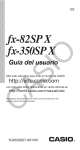
2.2
Probe base
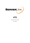
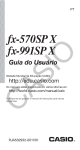
The probe base is made of solid titanium and is used for the attachment of
nearly all sensors. Fig.1 shows the principle arrangement of the sensor
positions.
Sea & Sun Technology GmbH / Arndtstraße 9-13 / D-24610 Trappenkamp / Germany
Tel ++49 (0)4323 910913 / Fax ++49 (0)4323 910915 / www.Sea-Sun-Tech.com
SST-CTD90M
user’s manual
page 6 / 51
Standard probe
The base offers space for 9 sensors: the pressure sensor is always mounted
in the centre position. For the remaining sensors there are 8 fits. The sensors
are inserted into these fits; the M4-tapped holes situated between the fits are
for fastening the sensor flange with M4-screws. All sensors (except the
pressure sensor) have identical flanges. The pressure transducer is inserted
to the base inside and held by a M18*1 nut against the pressure from outside.
A ¼“UNF28THD tapped hole is for connecting the base to a pressure gauge
so that the pressure sensor can be calibrated when installed.
Sea & Sun Technology GmbH / Arndtstraße 9-13 / D-24610 Trappenkamp / Germany
Tel ++49 (0)4323 910913 / Fax ++49 (0)4323 910915 / www.Sea-Sun-Tech.com
SST-CTD90M
user’s manual
page 7 / 51
Figure 1
CTP90M standard bottom
8
5
1
1/4" UNF 28THD
connection to
pressure gauge
2
4
8 standard fits for
bottom mounted sensors
3
7
6
CTP90M bottom with
integrated currentmeter or transmissiometer
fit for currentmeter
or transmissiometer
5
6
4
3
standard fits for
C,T,P,O2,pH,Red,Turb
2
1
Sea & Sun Technology GmbH / Arndtstraße 9-13 / D-24610 Trappenkamp / Germany
Tel ++49 (0)4323 910913 / Fax ++49 (0)4323 910915 / www.Sea-Sun-Tech.com
SST-CTD90M
user’s manual
page 8 / 51
CTD90M probe with integrated current meter or transmissiometer
The flange of the current meter and transmissiometer have a diameter of 40
mm and requires more space on the bottom than the standard sensors
(approximately 25 mm diameter). It is not possible to mount the pressure
transducer in the centre position. Hence the pressure sensor get its own
housing and is plugged in one of the five remaining standard fits. The
calibration connection thread for the pressure gauge then has the ISO size
M8 * 1,25 mm.
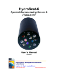
The printed circuit boards (PCB) are screwed on a bedplate made of 1,5 mm
aluminium sheet which is mounted on the inside of bottom cap.
Lid and pressure tube are sealed by two O-rings 76 * 2,5mm and are bolted
onto the side with 4 screws M3*4.
LEMOSA
connector
bottom cap with CTD - Sensors
bedplate
cable to
battery pack
analog board
160
digital board
pressure
transducer
temperature
sensor
bottom cap
conductivity cell
Sea & Sun Technology GmbH / Arndtstraße 9-13 / D-24610 Trappenkamp / Germany
Tel ++49 (0)4323 910913 / Fax ++49 (0)4323 910915 / www.Sea-Sun-Tech.com
SST-CTD90M
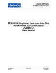
2.3
user’s manual
page 9 / 51
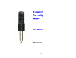
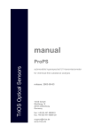
Probe lid
The lid has the same dimensions as the base and is also made of titanium.
Fastening and sealing are identical to that of the base. Screwed into the lid is
a supporting bolt with a loop for hanging it onto a shackle. The standard
version includes one underwater bulkhead connector SUBCONN MCBH5M
which is used for communication (configuration and data readout) and
external power supply and one operating control device. The control device
consists of a two colour LED for the display of operation conditions and
messages and a magnetic switch (reed contact) to turn on and off the
instrument. The Duo LED is located behind a pressure resistant glass
window, the position of the reed contact is marked by a small borehole in the
top cap surface.
configuration connector MCBH5M
suspension bolt
Position
of reed contact
glass window
with DUO LED
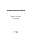
The battery box is fixed directly on the inside of the top cap. A circular printed
circuit board is mounted between lid and battery box. It contains the the
cabel-driver circuitry and FSK modulator and all the necessary wiring of
connectors, control device and battery pack. The connection to the probe
electronics is established by a separable 10 wire cable-connection.
Sea & Sun Technology GmbH / Arndtstraße 9-13 / D-24610 Trappenkamp / Germany
Tel ++49 (0)4323 910913 / Fax ++49 (0)4323 910915 / www.Sea-Sun-Tech.com
SST-CTD90M
user’s manual
page 10 / 51
Top cap with battery box
suspension bolt
control device
LED + reed contact
configuration connector
top cap
protection ring
inside PCB
cable driver & FSK modulator
battery box
batteries
8 * C size
battery box
top cover
cables to digital board
battery pack
standard version
LEMOSA connector
Sea & Sun Technology GmbH / Arndtstraße 9-13 / D-24610 Trappenkamp / Germany
Tel ++49 (0)4323 910913 / Fax ++49 (0)4323 910915 / www.Sea-Sun-Tech.com
SST-CTD90M
2.4
user’s manual
page 11 / 51
Sensor protection cage
A sensor protection cage made of 6 mm titanium rods with a diameter of 120
mm and a length of 220 mm is delivered with the standard version. The
protection cage protects the sensors on the water-floor against shocks and
ground contact and guarantees a fine water-flow through the sensors. The
protection cage is fastened with a single screw at the lower end of the
pressure pipe. As option any other size can be supplied. The version with
integrated current meter is supplied with a big size protection cage of 780mm
length and 220 mm diameter covering the complete probe.
2.5
CTD90M dimensions and weights
pressure tube
material:
titanium grade 2
length:
390 mm
diameter:
89 mm
wall thickness:
3 mm
depth capability:
500 m
bottom cap:
material:
diameter:
thickness
titanium grade 2
89 mm
30 mm
top cap:
material:
diameter:
thickness:
titanium grade 2
89 mm
30 mm
protection cage
material:
diameter
length
titanium grade 2
150 mm
200 mm
standard probe:
gross length
total weigth
bouyancy
650mm
4,8 kg
2,7 kg
Sea & Sun Technology GmbH / Arndtstraße 9-13 / D-24610 Trappenkamp / Germany
Tel ++49 (0)4323 910913 / Fax ++49 (0)4323 910915 / www.Sea-Sun-Tech.com
SST-CTD90M
3
user’s manual
page 12 / 51
Sensors
The CTD90M has a maximum of 16 analogue channels and 8 digital inputs or
outputs for the connection of different sensors. A maximum of 9 sensors fit
onto the bottom. The other sensors or instruments have to be connected
externally via additional underwater plugs in the sensor lid.
The following sensors can be accommodated in the sensor-base (bottom
mounted sensors without cable connection)
-
Pressure transducer
Ground runner
Temperature sensor Pt 100
Conductivity cell
Oxygen sensor
Ph and redox sensor
Seapoint turbidity meter
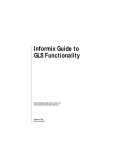
The standard sensors have the same flange with an integrated six-pin glass
feed through (400 bar) equipped with a small six-pin round connector (see
figure below). All of these sensors can therefore be removed from the outside
and can easily be replaced without having to open the probe.
standard
sensor
flange
2x O-rings 16x1.5
O-ring 13x1
6 pin glass
feedthrough
LEMOSA 6pin connector
Sea & Sun Technology GmbH / Arndtstraße 9-13 / D-24610 Trappenkamp / Germany
Tel ++49 (0)4323 910913 / Fax ++49 (0)4323 910915 / www.Sea-Sun-Tech.com
SST-CTD90M
user’s manual
page 13 / 51
External sensors
with analogue outputs and cable connection to the top cap of the CTD90M
fluorometer (Seapoint, TRIOS, Cyclops7)
current meter (hs engineers)
transmissiometer
light sensors (LI-COR)
multi water samplers (Hydro-Bios)
multi plankton nets (Hydro-Bios)
fast oxygen sensor (AMT), also available with standard flange
H2S sensor (AMT), also available with standard flange
methane sensor (CAPSUM)
can be attached and operated as external sensors. Power for external
sensors has to be supplied by the CTD90M. Standard supply voltage is 12
volt; supply up to 26 VDC is possible.
3.1
Pressure transducer
A piezo-resistive full bridge in OEM version with a diameter of 15 mm and a
total height of 6 mm is used as pressure transducer (produced by the Swiss
manufacturer KELLER). The casing and diaphragm are made of alloy C276.
The transducer is delivered with a small SMD-PCB and includes a
temperature compensation of the pressure measurement. The sensor is
mounted in the base of the probe; the SMD-board has contacts and is
plugged onto the main board of the probe.
Pressure transducer
Sea & Sun Technology GmbH / Arndtstraße 9-13 / D-24610 Trappenkamp / Germany
Tel ++49 (0)4323 910913 / Fax ++49 (0)4323 910915 / www.Sea-Sun-Tech.com
SST-CTD90M
user’s manual
page 14 / 51
Technical characteristics
-
Manufacturer
Model
-
Dimensions
Full scale range
Bursting pressure
Repeatability
Hysteresis
Zero drift
-
Precision
3.2
Ground runner
KELLER, Switzerland
PA7-XXX Progress
(XXX:= full scale range in bar)
15 mm diameter, 5,6 mm height
1, 2, 5, 10, 20, 50, 100, 200 bar
150 % of FS range
0,1 % of FS range
0,1 % of FS range
0,01 %/°C
reduced to 0,1%FS by Progress
0,1 % in the range of –5°...35°C.
The function of the ground runner is to recognize the sea floor in time during
profiling online. It helps avoiding damage to the sensors through ground
contact. The ground runner mainly consists of a mobile magnet and a reed
contact, which are held together by spring tension. During a profile the
magnet is pressed against the spring tension by a control weight on a line
and so kept away from the reed contact, the contact is open. If the control
weight has floor contact the spring release the tension and presses the
magnet to the reed contact which is then closed by the magnetic field.
The reed contact produces a digital signal, which is interrogated by the microcontroller.
3.3
Temperature sensor
The temperature sensor is a platinum resistor Pt100 in a tiny ceramic carrier
of 15 mm length and 0,9 mm diameter. It is fitted in a slender titanium tube
1,2 * 0,1 mm, about 30 mm long. This delicate tip is resistant to a pressure of
600 bar but it is extremely sensitive to knocks and inflection. Therefore the tip
is surrounded by a titanium perforated shield tube, which is mounted onto the
standard flange. The platinum resistor is connected in 4-wire technique.
Sea & Sun Technology GmbH / Arndtstraße 9-13 / D-24610 Trappenkamp / Germany
Tel ++49 (0)4323 910913 / Fax ++49 (0)4323 910915 / www.Sea-Sun-Tech.com
SST-CTD90M
user’s manual
page 15 / 51
Technical data
Manufacturer
Type
Measuring range
Response time
Repeatability
Accuracy
Maximum depth
3.4
SST
Merz Pt 100/1509
-2°C – 35°C
approx. 150 msec.
< 0,001°C
0.005°C
6000 m
Conductivity cell
Short description of measuring principle
All models of conductivity sensors use 7 electrodes in a cylindrical arrangement. The cell is always constructed symmetrically as depicted in the
following sectional drawing.
The central electrode D is used to impress alternating current of 500 Hz to 1
kHz frequency (square wave) into the water volume while both outside
electrodes A and G are the current return leads, which are held on a constant
potential. There exist two pairs of sensing electrodes (B, C and E, F), which
measure the voltage drop across them. The electrical field in a homogeneous
medium is symmetrically divided on both half-cells. The constant potential on
the outer electrodes limits the electrical field to the inside of the cylinder and
prevents any influence from boundary conditions outside the cell. The
conductivity electronic is mainly an automatic closed AC control loop which
hold the voltage drop across the sensing electrodes on a constant level, while
the current is proportional to the actual conductivity value.
Sea & Sun Technology GmbH / Arndtstraße 9-13 / D-24610 Trappenkamp / Germany
Tel ++49 (0)4323 910913 / Fax ++49 (0)4323 910915 / www.Sea-Sun-Tech.com
SST-CTD90M
user’s manual
page 16 / 51
Conductivity sensor for profiling
The conductivity cell consists of a quartz glass cylinder with 7 platinum
coated electrodes. Because of the small inner diameter of 8 mm the cell
needs a minimum vertical flow velocity to obtain full accuracy. The cell is
vulcanised with rubber in a mould. The cleaning procedure must be carried
out very carefully hence the glass cylinder is sensitive against shock and
impact.
Technical characteristics:
Manufacturer
Model
Cell factor
Ranges
Response time
Reproducibility
Accuracy
Maximum depth
Min. flow through the cell
ADM
7-pole electrode cell
K= 1,2
0 – 6 mS/cm – 65ms/cm
100 msec at 0,5 m/sec flow
< 2µS/cm
10 µS/cm
6000 m
5 cm/sec
Conductivity sensor (6000 m)
Combined CT sensor
Can be used up to 2000m instead of single sensors T and C
Specifications and description see 3.3 and 3.4.
Sea & Sun Technology GmbH / Arndtstraße 9-13 / D-24610 Trappenkamp / Germany
Tel ++49 (0)4323 910913 / Fax ++49 (0)4323 910915 / www.Sea-Sun-Tech.com
SST-CTD90M
user’s manual
page 17 / 51
3.5. Oxygen sensor
The oxygen sensor measures the dissolved oxygen in the water using
polarographic methods. The platinum cathode has a diameter of 4mm and is
encased with a teflon membrane. The oxygen current consumption ranges
from 0 to 12 µA due to the big diameter of the platinum wire. The relative high
current consumption requires a minimum current flow of 10 cm/sec in order to
avoid oxygen depletion in front of the membrane.
Technical data:
Manufacturer
Type
Polarisation voltage:
Range
Oxygen current
Temperature range
Response time
Accuracy
Maximum depth
SST/Oxyguard DO522M18
Clark electrode, self galvanizing
-0,7 VDC
0 – 150 %
0 – 12 nA
-2°C – 30°C
approx. 10 sec (98%)
+ /-3%
2000 m
Oxygen sensor without protection cap
Oxygen sensor with protection cap
Sea & Sun Technology GmbH / Arndtstraße 9-13 / D-24610 Trappenkamp / Germany
Tel ++49 (0)4323 910913 / Fax ++49 (0)4323 910915 / www.Sea-Sun-Tech.com
SST-CTD90M
user’s manual
page 18 / 51
3.6. pH and Redox sensors
3.6.1 Depth range 0..160m
pH and redox combined electrodes are industrial sensors using a solid
reference system (stiff polymer mass containing KCl) and an aperture
diaphragm which allows direct contact between reference electrolyte and
sample medium. Regeneration of the glass membrane or filling up electrolyte
is not possible. When the lifetime of the sensor is over, it has to be replaced
by a new one. The sensor has a thread PG 13,5 and is screwed into a flange.
A coaxial socket makes the electrical contact in the flange. Sealing between
sensor and flange is achieved by an O-ring, which is part of the sensor.
Technical data:
Manufacturer
Model
Measuring range
Maximum depth
Shaft diameter
Length with flange
Response time
pH
METTLER-TOLEDO
405-DXK-S8/120
4-10
160m
12 mm
167 mm
approx. 1 sec
Redox
METTLER-TOLEDO
Pt 4805-DXK-S8/120
-2000mV – 2000 mV
160 m
12 mm
167 mm
approx. 1 sec.
3.6.2. Depth range 0..500 m
pH and redox combined electrodes based on the same principles as
described in §3.6.1 but more pressure resistant.
Technical data:
pH
Redox
Manufacturer
Model
Maximum depth
Hamilton
Polylite PRO 120 XP
500m
Hamilton
Polylite RX 120 XP
500m
Other technical data same as above (see picture next page).
Sea & Sun Technology GmbH / Arndtstraße 9-13 / D-24610 Trappenkamp / Germany
Tel ++49 (0)4323 910913 / Fax ++49 (0)4323 910915 / www.Sea-Sun-Tech.com
SST-CTD90M
user’s manual
page 19 / 51
3.6.3. Depth range 1200m
This pH/ORP Sensor uses a pressure-balanced glass electrode with a
reference to provide in-situ measurements up to 1200m depth. The sensor is
equipped with a reference system using a solid gel (stiff polymer mass
containing Ag+-free KCl) and a ceramic pore diaphragm and with a pressure
stable pH-sensitive glassy electrode.The pH probe is permanently sealed and
supplied with a soaker bottle attachment. The bottle contents must be 3 M
KCl solution (pH 4) that prevents the reference electrode from drying out
during storage.
This sensor is absolutely H2S resistant.
PH
Manufacturer
Measuring range
Maximum depth*
Shaft diameter
Shaft material
Bulkhead material
Thread
Shaft length
Length with flange
Response time
AMT GmbH
4-10
1200m
12 mm
transparent plastic
Stainless steel
G1/4 (ISO228)
84mm
117 mm
approx. 1 sec
Redox
AMT GmbH
-2000mV.. – 2000 mV
1200 m
12 mm
transparent plastic
stainless steel
G1/4 (ISO228)
84mm
117 mm
approx. 1 sec.
* This sensor is pressure resistant up to several thousand meters depth
with a slight increase of pH/ORP values.
Sea & Sun Technology GmbH / Arndtstraße 9-13 / D-24610 Trappenkamp / Germany
Tel ++49 (0)4323 910913 / Fax ++49 (0)4323 910915 / www.Sea-Sun-Tech.com
SST-CTD90M
user’s manual
page 20 / 51
3.7. Seapoint turbidity sensor
The bottom mounted turbidity sensor is based on the SEAPOINT turbidity
meter in the bulkhead version, which is screwed onto a standard flange.
Electrical connection is achieved by a separable 6 pin round connector. For
further details please refer to SEAPOINT´s manual.
The Turbidity sensor measures the concentration of suspended matter. It is
equipped with a pulsed infrared light transmitter and detects the scattered
light from the particles suspended in water. Transmitter and detector
arrangement uses 90° scattering at a wavelength of 880 nm. The output
signal is proportional to the particle concentration in a very wide range. For
detailed description of Seapoint turbidity meter refer to the special user
manual.
Specifications:
Power: 7 – 20 VDC, 3,5 mA average
Signal: 0...5 VDC (each range)
Scatterance angle: 90° avg. (15...150°)
Light source wavelength: 880 nm
Linearity: 2%
Depth capability: 6000 m
Size: 2,5 cm diameter, 11 cm length
Ranges: 0-25, 0-125, 0-500, 0-2500 FTU
Picture shows the bulkhead version with flange
The turbidity sensor is available in two different versions: standard version
has an underwater plug, is connected to the probe via a 6-wire cable and has
to be fixed to the probes protection cage with a clamp. The Bulkhead version
is plugged into a fit of the bottom cap of the probe and hence needs no
underwater connection cable. The range can be selected by hardwiring
according to the customers requirements.
Sea & Sun Technology GmbH / Arndtstraße 9-13 / D-24610 Trappenkamp / Germany
Tel ++49 (0)4323 910913 / Fax ++49 (0)4323 910915 / www.Sea-Sun-Tech.com
SST-CTD90M
user’s manual
page 21 / 51
3.8. Cyclops7 Fluorometer
The Cyclops 7 used here for MSS90 is the standard Cyclop-7 instrument from
Turner Design. In order to adapt the instrument to the probes end cap the
Subconn connector was skipped and instead our standard flange was
screwed into the connectors thread. To avoid corrosion problems the
cyclops7 housing is made of titanium. The gain setting lines can be set to a
range of 0..5, 0..50 or 0..500µg/l. The selection of the gain is made inside the
profiler by the use of two SIL switches. The instrument is delivered with the
default range 0..50µg/l (gain setting = *10)
For details and hints for application please refer to turner´s user manual.
The manual is available on the CD ROM.
3.9. Multirange sensors
There are a number of sensors, which have several measuring ranges with
different sensitivities on a single analogue output. The CTD90M supports
these multirange sensors by automatic range switching and transmits
measurement values and range information to the board unit in a single 16 bit
word. Analogue values have 16-bit resolution. The range code consists of 2
bits and occupies the two least significant bit of the 16 bit measuring value.
This limits the real resolution of the multirange sensors to 14 bits. But since
all these sensors doesn’t need CTD resolution the overall accuracy is not
affected by this procedure.
3.9.1. Seapoint turbidity meter
Description is given in §3.7. Beside the hardwiring of the selected range the
CTD90M offers the possibility of automatic range switching.
Both versions have 4 ranges, which are controlled by two independent gain
control lines A and B:
Sea & Sun Technology GmbH / Arndtstraße 9-13 / D-24610 Trappenkamp / Germany
Tel ++49 (0)4323 910913 / Fax ++49 (0)4323 910915 / www.Sea-Sun-Tech.com
SST-CTD90M
user’s manual
page 22 / 51
range
B
A
gain
calibration range
0
1
2
3
0
1
0
1
0
0
1
1
*1
*5
*20
*100
0...2500 FTU (linear up to 1000 FTU)
0.....500 FTU
0 125 FTU
0
25 FTU
0:= line tied to GND
1:= line left open
The CTD electronic monitors the signal output of the turbidity sensor and
selects automatically the next suitable range if a certain limit is exceeded or
dropped. The limits are approximately 10% resp. 90% of the current range.
The instrument is factory calibrated with a formazine turbidity standard.
3.9.2. LI-COR Quantum sensor
is used for measuring Photo synthetically Active Radiation (PAR) in aquatic
environments. Due to its 400 – 700 nm quantum response it is a suitable
sensor for investigation of the primary production. LICOR offers two different
underwater sensors:
LI-192SA cosine corrected quantum sensor (following Lambert’s cosine law)
measures the Photosynthetic Photon Flux Density (PPFD) through a plane
surface (photon or quantum irradiance between 400 and 700 nm)
Sea & Sun Technology GmbH / Arndtstraße 9-13 / D-24610 Trappenkamp / Germany
Tel ++49 (0)4323 910913 / Fax ++49 (0)4323 910915 / www.Sea-Sun-Tech.com
SST-CTD90M
user’s manual
page 23 / 51
LI-193SA spherical quantum sensor determines specifically the
Photosynthetic Photon Flux Fluence Rate (PPFFR), the number of photons in
the visible range incident per unit time on the surface of a sheer divided by its
cross sectional area.
Both instruments are calibrated in µmol/s*m2 (µE) where 1 µmol is 6,023 *
10-17 photons.
Specification:
Detector: silicon photodiode
Range: 0 ... 10000 µmol/s*m2
Calibration accuracy: 5%
Linearity: 1%
Long term stability: 2% per year
depth capability: 350 m (LI-193SA) / 550 m (LI-192SA)
Sensitivity: typical 3 µA / 1000µE
Both sensors will be connected to the probe by a 2 wire underwater cable.
Please note: the light sensors must be mounted on the top of the probe to
avoid shade of neighboured instruments.
Sea & Sun Technology GmbH / Arndtstraße 9-13 / D-24610 Trappenkamp / Germany
Tel ++49 (0)4323 910913 / Fax ++49 (0)4323 910915 / www.Sea-Sun-Tech.com
SST-CTD90M
user’s manual
page 24 / 51
The dynamic measuring range (sensitivity of the photodiode) covers approximately 7 to 8 decades of light intensity. Logarithmic amplifiers have a different
resolution depending on the current value. To avoid this disadvantage the
complete range is divided into 4 decades each with 14-bit resolution.
range
0
1
2
3
range code
0
1
0
1
current [µA]
0
0
1
1
PPFFR / PPFD (*)
0.....0,05
0 0,5
0.....5
0 50
0........12
0......125
0....1250
0..12500
(*) calculated for LI-multiplier of 250
The result is a linear response from 0,001 up to 10000 µmol/s*m2.
Range switching is executed automatically when the measuring value
increases the 95% full scale level or decreases 5% FS of the current range.
3.9.3. Seapoint Fluorometer
measures chlorophyll A concentration in 4 different ranges, which are selected by two control lines A and B
range
0
1
2
3
range code (B/A)
0
1
0
1
0
0
1
1
Concentration [µg/L]
0....150
0
50
0
15
0........5
Sea & Sun Technology GmbH / Arndtstraße 9-13 / D-24610 Trappenkamp / Germany
Tel ++49 (0)4323 910913 / Fax ++49 (0)4323 910915 / www.Sea-Sun-Tech.com
SST-CTD90M
user’s manual
page 25 / 51
The range switching procedure is similar to the turbidity meter; the limits are
90% and 10% of full scale.
The instrument has a six pin underwater plug (Impulse AG306) and has to be
connected by a cable to the CTD.
Specifications:
Power: 8 – 20 VDC, 15 mA average
Signal: 0 – 5 VDC (each range)
Light source: blue LED 470 nm
Detector: photodiode 680 nm
Min. detection level: 0,02 µg/l
Depth capability: 6000 m
Size: 64 mm diameter, 168 mm length
The instrument is also available in a version to measure DOC (dissolved
organic matter or yellow substances).
Sea & Sun Technology GmbH / Arndtstraße 9-13 / D-24610 Trappenkamp / Germany
Tel ++49 (0)4323 910913 / Fax ++49 (0)4323 910915 / www.Sea-Sun-Tech.com
SST-CTD90M
4
user’s manual
page 26 / 51
Replacement of sensors, opening the probe
When replacing a sensor the probe generally doesn’t have to be opened
(exception: pressure sensor and Cyclops). Proceed as follows:
-
remove the M4-screws which hold the flange
carefully remove the respective sensor whilst gently turning it out of its
fitting in the base
disconnect the plug contacts (pull lightly).
Reassemble in opposite order. To remove the pressure sensor the probe has
to be opened. This is done in the following order:
-
remove the protection case
take the lid off: first of all unscrew the 4M3-screws on the side of the
tube-end and then pull the lid off whilst gently turning it without tilting it
detach the base from the tube (as with the lid)
disconnect all of the sensor plugs, unsolder the pressure sensor cable
on the main board
detach the bedplate from the base, unscrew the pressure sensor
holding screw
pull the sensor out carefully by its cable (from 100 m range upwards
blow it out, if necessary, with compressed air from the front side)
Attention: When replacing the pressure sensor the progress-print must
always be replaced as well because it contains the temperature
compensation for the specific pressure sensor. When inserting the new
pressure sensor grease the O-ring thoroughly. Reassembling is done in the
opposite sequence.
Sea & Sun Technology GmbH / Arndtstraße 9-13 / D-24610 Trappenkamp / Germany
Tel ++49 (0)4323 910913 / Fax ++49 (0)4323 910915 / www.Sea-Sun-Tech.com
SST-CTD90M
5
user’s manual
page 27 / 51
Probe electronics
The electronics of the basic version consists of 3 printed circuit boards
1.
2.
3.
4.
5.1
Power supply and cable driver (located between battery box and lid)
Analog main board and plug-in modules.
Digital main board
Expansion board
Probe power supply
is situated on a small circular board (40 mm diameter), which is screwed to
the inside of the lid. This board contains the FSK modulator, the cable driver
and the zenerdiode for constant current supply. Components, which produce
a considerable heat, are screwed onto the lid, thus using the good thermal
contact for heat abduction to the metal housing and seawater (cable driver
transistor, zenerdiode). The wires of the probes underwater connector are
soldered onto this board; the connection to the main board is separable by a
plug.
5.2
The main board
Measures 150 mm * 50 mm and contains the following circuitry:
-
Data acquisition
16-channel analogue multiplexer
RS-232 driver
Water sampler releaser
Temperature module
Conductivity module
Pressure amplifier (with Progress-print as plug-in module)
Oxygen amplifier
Redox amplifier
PH amplifier
Differential amplifier for sensors with analogue output
The main board has an expansion plug which contains all necessary signals
for a system extension to 32 sensors. On the backside of the bedplate a
further same sized additional printed circuit board can be attached which
incorporates the electronics for further sensors.
Sea & Sun Technology GmbH / Arndtstraße 9-13 / D-24610 Trappenkamp / Germany
Tel ++49 (0)4323 910913 / Fax ++49 (0)4323 910915 / www.Sea-Sun-Tech.com
SST-CTD90M
user’s manual
page 28 / 51
The heart of the probe is a microprocessor controlled 20-bit analogue digital
converter, which generates an auto calibration cycle each time the probe is
switched on. This results in an exceptionally good long-term stability. This is
especially important for the stability and precision of the CTD sensors.
5.3. Digital board
Contains the following circuitry
- Processor in and out ports
- Toggle switch for reed contact
- RS232 driver and receiver
- Flash memory
- Power supply and regulation (+5V,-5V, 3,3V)
- Power switch for external devices
5.4. Expansion board
The expansion board is equipped with a second 8-channel analogue
multiplexer for the upper address range from 16 to 23. This board provides
the plug in position for all multirange sensor electronics and the interface
circuitry for current meter and compass.
Sea & Sun Technology GmbH / Arndtstraße 9-13 / D-24610 Trappenkamp / Germany
Tel ++49 (0)4323 910913 / Fax ++49 (0)4323 910915 / www.Sea-Sun-Tech.com
SST-CTD90M
user’s manual
page 29 / 51
6. Connector pin assignment, power supply and interfaces
The CTD90M has a 5-pin underwater connector which allows the probe to be
operated in different modes. The standard connector is SUBCONN MCBH5M
made of titanium and neoprene.
1
5
4
2
3
Face view of bulkhead underwater connector
Connector pin assignment:
Pin 1.....Constant current loop, FSK Signal (option)
Pin 2 TxD, transmit data RS232C
Pin 3 Constant current loop return, Power GND, RS232 GND
Pin 4 + Power input (10..15 Volt)
Pin 5 RxD, receive data RS232C
Mating cable is Subconn MCIL5F with locking sleeve MCDLSF
6.1. Internal batteries
6.1.1. 12V Battery
The battery box is a circular shaped housing of 75 mm diameter and
approximately 140 mm height and mounted on the top cap of the memory
probe. The box is designed for 8 alkaline batteries of size C. The batteries are
packed in series which guaranties a supply voltage of 12 VDC (8 * 1,5 volt)
at full capacity of 7..8Ah. All battery contacts are springs which are loaded
and they assure a safe operation without power interuption even under stress
and shock conditions and rough handling. For exchange of batteries you have
Sea & Sun Technology GmbH / Arndtstraße 9-13 / D-24610 Trappenkamp / Germany
Tel ++49 (0)4323 910913 / Fax ++49 (0)4323 910915 / www.Sea-Sun-Tech.com
SST-CTD90M
user’s manual
page 30 / 51
to pull carefully the top cap off the pipe (after having unscrewed before the
four screws M3 at the tubes end). Then separate the cable connection to the
electronics and remove the cover of the battery box (screw M6). Insert the
new batteries in the correct sequence as depicted on the battery box housing.
Closing of the instrument is done in the opposite order. Please take care that
the O-rings of the top cap are always lubricated with silicone grease. Spare
O-rings are part of the delivery.
Specifications:
Batteries:
Type
Nominal capacity:
IEC designation:
Size:
Power consumption:
Lifetime:
8 * 1,5 volt C cells
alkaline
7 - 8 Ah
LR14
26 * 52 mm
20mA for C;T,D,O2,pH,redox
approximately 300 hours continious operation
The CTP90M is protected against low battery. In memory mode (data storage
active) the probe probe is switched off when the battery voltage falls below
9,5 VDC and can only be activated by connetion to a PC via RS232
communication.
For units with high current consumption a batterie box with 8 D cells is
available (see appendix)
6.1.2. 3V Battery
If there is no need to supply third party instruments with higher voltages than
5V , a 3 volt supply is more effective. The length of the probe is 50mm shorter
than the basic version.
Specifications:
Batteries:
Type
Nominal capacity:
IEC designation:
Size:
Power consumption:
Lifetime:
4 * 1,5 volt C cells
alkaline
7 - 8 Ah
LR14
26 * 52 mm
50..80mA for C;T,D,O2,pH,redox
approximately 250 hours continuous operation
Sea & Sun Technology GmbH / Arndtstraße 9-13 / D-24610 Trappenkamp / Germany
Tel ++49 (0)4323 910913 / Fax ++49 (0)4323 910915 / www.Sea-Sun-Tech.com
SST-CTD90M
user’s manual
page 31 / 51
6.2. External power supply
The memoryprobe can be powered externally via cable connection to an
external battery or a DC power supply (regulated or unregulated). The
external supply voltage may range from 9 to 15volt. The internal batteries
need not to be removed, they are polarity protected by a diode against higher
voltage. The memory probe is then supplied by the source with the higher
voltage.
External Power Connection: Pin 3
Pin 4
Power GND
Power In (9...15 VDC)
6.3. Operation with multicore cables
The use of multicore cables is adviseable for shorter distances between
probe and PC and paricularily in a laboratory. The probe is then supplied
either by a battery or an external power supply. The voltage is applied to
Pin3 (negative) and Pin4 (positive). Online data transfer to the PC is via pin2
(Transmit data TxD) and pin3 (GND). The RxD input line of the probe must be
connected to the PC in order to enable the data transfer.
memory probe
inline cable
Signal
PC / Power supply
Signal
connector
Pin 2
Pin 3
Pin 5
RxD
GND
TxD
TxD
GND
RxD
if external supply is provided
Pin 3
Power GND
Pin 4
Power In
Pin 2 (SUB D 9)
Pin 5 (SUB D 9)
Pin 3 (SUB D 9)
Power GND banana plug black
Power out
banana plug red.
The maximum length of the multicore cable data link depends mainly on the
cable resistance and capacitance and can at best be several hundred meters.
An advantage is that a specific interface between probe and PC is not
necessary.
6.4. Configuration cable
Sea & Sun Technology GmbH / Arndtstraße 9-13 / D-24610 Trappenkamp / Germany
Tel ++49 (0)4323 910913 / Fax ++49 (0)4323 910915 / www.Sea-Sun-Tech.com
SST-CTD90M
user’s manual
page 32 / 51
It is delivered with the memory probe and is intended to be used for all kind of
communication between probe and PC:
-
Configuration of the operation modes
Data readout of stored files
online transmission of data in laboratory
The length of the configuration cable is about 5 m, the wiring is described
below:
memoryprobe
Pin 2
Pin 5
Pin 3
Pin 3
Pin 4
TxD
RxD
GND
Power GND
Power in
PC serial port / Power supply
RxD
TxD
GND
Power GND
Power out
Pin 2 (9 pole SUB D)
Pin 3 (9 pole SUB D)
Pin 5 (9 pole Sub D)
Banana plug black Banana plug red +
6.5. Operation with single conductor cables
The standard application of CTD probes is profiling performed via winches
with slip rings and single conductor cables. The CTD90M is then supplied by
constant current, the FSK signal is superimposed on the constant current as
voltage modulation. An interface between PC and winch (probe) produces the
constant current and convertes the FSK-signal from the probe into PCcompatible RS232C data. The maximum voltage of the current source
depends on the cable resistance (cable length). The wiring is as follows:
Inline cable
Pin 1
Pin 3
Signal
+ current/FSK-signal
- current loop return
coax cable
inner wire
shield
The basic version has a constant current of about 100 mA, this can be
distinctly higher when external devices are connected. The voltage drop
between Pin 1 and Pin 3 is approximately 17 volt. The FSK signal is a
sinusoidal signal of approx. 5Vss and modulated on the constant voltage
level. A logic LOW-level is the equivalent to the low frequency, a functional
HIGH-level is equivalent to the higher frequency. Standard baudrate is 1200,
FSK frequencies are 2400 and 4800 Hz. The FSK signals runs synchronically
with the data signals.
Sea & Sun Technology GmbH / Arndtstraße 9-13 / D-24610 Trappenkamp / Germany
Tel ++49 (0)4323 910913 / Fax ++49 (0)4323 910915 / www.Sea-Sun-Tech.com
SST-CTD90M
user’s manual
page 33 / 51
The TxD signal on pin 2 of the probe connector is identical with the RS232
output of the probe interface.
7. Operating the memory probe
7.1. Control elements
On the top cap of the memory probe there is a duo coloured LED and a reed
contact located behind a glass window. The LED´s are used to display
operating conditions:
-
red LED on.......................Power on
red LED off.......................Power off
green LED blinking...........Storage of data
The green LED is on only the short time, data is written to the flash eprom.
Red and green LED on at the same time result in light yellow colour.
When the probe is connected to a power source (either battery or external
power supply) it is always operating in an unconfigurated mode (without valid
configuration) transmitting data without data storage. The probe then can be
switched off with the magnet.
Power switching is executed under several conditions:
1. A signal on the RxD line turns the power on in any mode. The start
communication command in the user menu is used to switch the probe on
and interrupts the current operating mode.
2. Activation of the reed contact turns the power on and starts the selected
operation mode (except FSK mode and time mode).
3. Detection of turn on time (time mode) switches the power on.
4. Detection of FSK status bit turns the probe automatically on
Reed contact:
The activation of the reed contact is made by a magnetic rod (part of the
delivery). The rod should be led vertically with the magnetic tip to the
indicated borehole near the glass window for not more than a second. The on
Sea & Sun Technology GmbH / Arndtstraße 9-13 / D-24610 Trappenkamp / Germany
Tel ++49 (0)4323 910913 / Fax ++49 (0)4323 910915 / www.Sea-Sun-Tech.com
SST-CTD90M
user’s manual
page 34 / 51
condition is displayed by the red LED. A second activation turns the power off
(red LED off).
7.2. Operation modes
The probe has 3 configurable data storage modes :
- time mode
- increment mode
- continuous mode
and 2 on-line modes :
- FSK mode
- RS 232 on-line mode
The first 3 operation modes can be configured by the supplied Windows(tm)
software package "Sea & Sun Technology´s Standard Data Acquisition" . See
separate manual for a complete software description. Generally the memory
probe has to be configured by use of this software prior to data storage
applications. Data readout and conversion to ASCII-files is done by this
software, too. In addition to storage modes the probe can be used like a
standard direct reading probe using FSK or RS232 data tranmission. During
all data storage modes the measured data is transmitted via the RS232
output to a connected PC. To save battery power the RS232 output is
powered down if no valid RS232 voltage level is present at the RXD line of
the probe.
7.3. Time mode
Time mode is configured by several parameters to best suit the data
acquisition tasks of the application. The most obvious is the time interval
between two consecutive wake-up periods. The second is the length of time
the probe is switched on after wake-up. There is a "Start time", where the
first interval starts and an optional "Stop time" after that the probe will
terminate the time mode. During the OnTime either all datasets are stored or
only those at a defined time grid. The parameters for Start Time and Interval
are mandatory, all others are optional for convenience.
Sea & Sun Technology GmbH / Arndtstraße 9-13 / D-24610 Trappenkamp / Germany
Tel ++49 (0)4323 910913 / Fax ++49 (0)4323 910915 / www.Sea-Sun-Tech.com
SST-CTD90M
user’s manual
page 35 / 51
7.4. Increment mode
Mostly this mode is used to obtain depth profiles with datasets stored at userdefined depth levels in order to achieve appropriate data reduction. The
"delta interval" between two consecutive depth levels has to be entered.
Optionally a start depth and/or a stop depth can be defined. After crossing
one of those depth levels one complete dataset is stored and the internal
processor of the probe calculates the next depth level to be crossed. Even if
the same limit is crossed again later on, no additional data is stored!
More than one profile can be obtained without the necessity for data readout
to a PC in between. A maximum of 250 files can be stored in this mode as
long as the capacity of the internal solid state memory is not exhausted ( 64
MegaBytes). For each profile the probe has to be switched on by use of the
magnetic rod. At that moment the next file is created in the memory. If a stop
depth was defined the probe will automatically switch-off at that depth and
close the current data file. Otherwise the probe has to be switched off
manually when it is raised to the surface ( and switched on again for the next
profile and data file).
7.5. Continuous mode
At this mode all acquired datasets are stored in the internal memory of the
probe. Each time the probe is turned on by use of the magnetic rod a new
(additional) file is created in the probe and all further datasets are stored until
the probe is switched off again.
7.6. FSK mode
Connecting the memory probe to an Interface for single conductor cables
enables the memory probe to enter FSK mode. In this mode all data storage
operations are disabled. The probe turns on automatically when it is powered
by the Interface and finishes the FSK mode after power down. The probe acts
like a true direct reading probe, i.e. all previous storage configurations are
terminated ( and have to be activated later on by connecting the probe to the
PC software). This mode is the only mode where the probe cannot be
switched off by the magnetic rod!
Sea & Sun Technology GmbH / Arndtstraße 9-13 / D-24610 Trappenkamp / Germany
Tel ++49 (0)4323 910913 / Fax ++49 (0)4323 910915 / www.Sea-Sun-Tech.com
SST-CTD90M
user’s manual
page 36 / 51
7.7. RS 232 on-line mode
is an operation mode without valid configuration. The memory probe enters
this mode after power on under following conditions:
-
After each first Power On (Battery exchange)
The stop-time in time mode operation is reached.
FSK-mode has been finished
The internal data storage memory is full
Further data storage is disabled by the PC-software
No data storage is possible, the probe awaits another configuration and acts
like a direct reading probe after being switched on by the magnetic rod.
Power is derived from the internal battery or external power supply. The
probe can opperate in this mode for unlimited time until it is switched off by
the magnetic rod.
7.8. Command mode
When the PC-software is urged to "Start communication" with the memory
probe then it switches the probe into the command mode to start
configuration or readout data. During command mode no data is acquired and
any data storage in progress is temporarily disabled and will be resumed after
end of command mode ( if wanted). If time mode is active during command
mode the time-grid updates are done in background, but no data acquisition
is performed! Time mode will resume after leaving the command mode and
start at the next configured interval in the future.
During data readout the communication baudrate is (automatically) set to
115200 Baud to speed up the process.
Command mode is left by closing the configuration window of the PC
software.
Sea & Sun Technology GmbH / Arndtstraße 9-13 / D-24610 Trappenkamp / Germany
Tel ++49 (0)4323 910913 / Fax ++49 (0)4323 910915 / www.Sea-Sun-Tech.com
SST-CTD90M
user’s manual
page 37 / 51
8. Service and maintenance
The best maintenance for the probe is to handle it with care. Despite the fact
that the probe is sturdily and stabile designed, unnecessary strains like
knocking and shocks should be avoided. Apart from that, there are only few
instructions and maintenance rules, which should be heeded or met to, so as
to ensure a longer life span and correct measuring, results.
8.1. The underwater connector
Is actually maintenance-free. However it has proved itself to be advisable to
lubricate the sealing surfaces of the pins with sea waterproof grease. This
reduces wear whilst plugging and unplugging. Further tips:
-
clean the plugs with warm soapy water. They do not have to be dried.
Chemicals should be avoided.
To avoid corrosion never plug or unplug whilst under water
To conserve the cable plug never unplug by pulling on the cable. Avoid
bending radiuses and above all narrow, sharp kins.
Plugs that are not in use should never be left blank. They should always
be protected against corrosion by a dummy cap.
8.2. Pressure sensor
The pressure sensor doesn’t require special attendance or maintenance.
Personally experience has shown however, that the pressure sensors should
never be tested by pressing a pin onto the membrane. This often causes
damage of the membrane or dents it, which can lead to pressure reading
mistakes or to a total damage. Pressure sensors damaged in such a way are
not covered by the guarantee.
8.3. The temperature sensor
The temperature sensor is maintenance free. Dirt and plant cover only
prolong the time constant but have no effect on the precision. When cleaning
the sensor take special care of the sensitive tip, which should not be bent.
Sea & Sun Technology GmbH / Arndtstraße 9-13 / D-24610 Trappenkamp / Germany
Tel ++49 (0)4323 910913 / Fax ++49 (0)4323 910915 / www.Sea-Sun-Tech.com
SST-CTD90M
user’s manual
page 38 / 51
8.4. The conductivity cell
Is principally not maintenance free. It must regularly be inspected for plant
cover and electrolytic calcification. Both effects reduce the measured
conductivity. It is appropriate if the probe is rinsed on deck with fresh water
after each application. This prevents the formation of salt crystals on the cell
surface. Calcareous deposits, which originate from the electrical current flow
in the cell, are easily removed if the cell is immersed for a few minutes in a
diluted acid. The quantity of rising CO2-bubbles gives information on the rate
of calcification. The cell is completely decalcified when the bubble formation
has ceased. Afterwards the cell has to be rinsed with fresh water. Depending
on the operating time this procedure is only necessary every few months.
Cleaning is more difficult after long-time application especially during warm
months, when heavy sea-pest growth densely populates the cell within a
short time (2 weeks). In this case the cell has to be placed into diluted acid (if
necessary for a longer time) and then a plastic bottlebrush has to be pushed
through it. This procedure may have to be repeated until the cell is completely
cleaned. Then the cell is rinsed with fresh water. Particular care has to be
taken, that the metal components on the electrode surfaces are not
scratched, nor must they come into contact with other metals. Otherwise the
lifetime of the cell and the long-time stability of the conductivity
measurements will be impaired. After the electrodes have been treated with
acid a short-term increased conductivity reading may occur, this should
normalize itself within an hour.
8.5. Oxygen sensor
The oxygen sensor requires some attention from time to time. All the
necessary maintenance like exchange of electrolyte and membrane is
described in an OxyGuard leaflet in the appendix of this manual.
The red O-ring has two different positions:
1. in the front position (shown in the picture below) the O-ring prevents
leakage of the electrolyte through the thread during storage. This
position should not be used for measurements but only for
storage.
Sea & Sun Technology GmbH / Arndtstraße 9-13 / D-24610 Trappenkamp / Germany
Tel ++49 (0)4323 910913 / Fax ++49 (0)4323 910915 / www.Sea-Sun-Tech.com
SST-CTD90M
user’s manual
page 39 / 51
2. in the backward position it allows the electrolyte to build a high
impedance electrolytic connection between medium (sea water) and
electrolyte room behind the membrane. This connection is necessary
for proper measurements. Please take care that during
measurements the O-ring takes always the backward position
The Oxyguard DO sensor is supplied by us with a sensor protection cap
made of plastic . To achieve a tight fit to the sensor head the cap is equipped
with an O-ring 21*1 mm and a 2mm hole in the center of the bottom (see
photo). The cap should be used as protection for the membrane and sensor
head as well as useful tool for oxygen field calibration.
If the membrane tension is dropping during operation or time the sensors
output signal is changing too. The zero point of the oxygen sensor remains fix
during its lifetime but the sensivity (slope) can vary. The user can execute a
field calibration after each membrane exchange or when he doesn´t trust the
measured values anymore.
Sea & Sun Technology GmbH / Arndtstraße 9-13 / D-24610 Trappenkamp / Germany
Tel ++49 (0)4323 910913 / Fax ++49 (0)4323 910915 / www.Sea-Sun-Tech.com
SST-CTD90M
user’s manual
page 40 / 51
Field calibration
The SDA software offers the possibility to perform a field calibration and to
change the reading automatically. Let the SDA program run with the probe
connected to the PC. The field calibration procedure is very simple:
-
-
Keep the membrane of the DO sensor dry
Put the red o-ring in the backward position
plug the protection cap onto the sensor head with a proper fitting o-ring
Fill a small plastic cup with water and immerse the sensor head up to the
flange (small white plastic cup is part of the delivery)
after a short time the enclosed air in the cap is water vapour saturated and
the the oxygen reading should have 100% partial pressure.
If the oxygen reading is stable click menu point Calibrate and 02 Field
Calib
When O2 Field Calib is selected, the current oxygen reading is
automatically stored. The default value 100% is accepted when clicking on
the button Calculate slope now.
The SDA programm calculates the new oxygen Field calibration coefficient
(originally 1) and the reading is now 100%.
The field calibration method works in any basin or tank and the result is
independent of the salinity. When putting the complete probe into a basin you
have to estimate the immersion depth of the oxygen sensor (measured from
the membrane to water surface). Every 10 cm immersion depth lead to an
increase of the oxygen reading of 1%. So e.g. if the procedure is executed
with the DO sensor 30cm below the water surface, the default value in the
button field Enter desired value has to be changed to 103%.
8.6. pH and Redox sensor (160m + 500m)
Both sensors are principally maintenance free. After its life span has ended
the corresponding sensor has to be replaced. When unscrewing the sensors
no moisture (e.g. water drops) what so ever must reach the contacts (dry
beforehand). A single drop of saltwater is enough to cause long-lasting
incorrect measurements – this is due to the high output impedance of 100 –
400 MΩ. So only replace sensors under clean and dry conditions please.
Please note: screwing the Mettler Toledo pH or ORP into the socket of
the flange must be executed very carefully in order not to damage the
plastic thread of the sensor. Tighten the sensor only by hand, don´t use
a tool. Damaged threads are not covered by warranty.
Sea & Sun Technology GmbH / Arndtstraße 9-13 / D-24610 Trappenkamp / Germany
Tel ++49 (0)4323 910913 / Fax ++49 (0)4323 910915 / www.Sea-Sun-Tech.com
SST-CTD90M
user’s manual
page 41 / 51
The life span of the sensors ceases when the response time of the pH or
redox measurement drastically increases. The life span also ends when the
reference electrolyte is dissolved down to the screw thread rim. Water can
then possibly leak in through the bolting.
Caution: Do not expose these pH or ORP sensor to H2S
The pH and Redox sensors are particularly endangered when they get into
contact with H2S in water. Some minutes in water containing hydrogen
sulphide is enough to irreparably ruin the sensor. In most cases stablemeasuring results cannot be achieved anymore despite lengthy rinses with
cleansing or buffer solutions. If measurements in H2S-concentrations are
necessary we recommend to remove the sensors and to screw on locking
caps (or to use the 1200m sensor; refer to 8.7.)
Special care has to be taken that before using the sensor no air bubble is to
be found in the pH electrolyte directly behind the ion-permeable glass layer
because it would interrupt the internal electrical connection to the pH
electrode. The air bubble has to be shaken out – similar to the shaking of a
thermometer. The air-bubble often occurs when the sensor has been stored
horizontally for a longer time.
8.7.
pH/ORP sensor (1200m, H2S resistant)
Do never touch the sensitive tip. Protect the pH-sensor with the delivered
soaker bottle containing the storage solution and avoid any dry out of the
sensitive tip.
Avoid any air inside the bottle, fill completely with 3 M KCl. Make sure, that
only 3 M KCl with pH 4 buffer is used for storage. It is not allowed to use
other wetting caps in order to avoid any air pressing into the diaphragm
leading to sensor malfunctions or damage. Damage because of using other
wetting caps or storage without any wetting cap is not covered by guarantee.
The pH sensor has to be rinsed carefully with fresh water after finishing the
measurements.
Sea & Sun Technology GmbH / Arndtstraße 9-13 / D-24610 Trappenkamp / Germany
Tel ++49 (0)4323 910913 / Fax ++49 (0)4323 910915 / www.Sea-Sun-Tech.com
SST-CTD90M
user’s manual
page 42 / 51
The pH sensor is a replacement part and has to be changed, if the sensor
has reached the lifetime. The sensor has a stainless steel thread G1/4A
(titanium on request) which is screwed into a flange. The electrical contact is
made by a socket in the flange. Sealing between sensor and flange is
achieved by an O-ring which is part of the sensor. After the sensor’s life span
has ended, the sensor has to be replaced.
8.8. Seapoint turbidity meter
The turbidity sensor has to be cleaned from time to time. Especially the
optical sensitive flat surfaces have always to be kept clean. Avoid the use of
chemical solvents.
8.9. Cyclops7 Fluorometer
The Chlorophyll A sensor has to be cleaned from time to time. Especially the
optical sensitive flat surface has always to be kept clean. Avoid the use of
chemical solvents. Make use of the protection cap if the sensor is not in
operation.
Sea & Sun Technology GmbH / Arndtstraße 9-13 / D-24610 Trappenkamp / Germany
Tel ++49 (0)4323 910913 / Fax ++49 (0)4323 910915 / www.Sea-Sun-Tech.com
SST-CTD90M
user’s manual
page 43 / 51
9. Probe data format
The probe data can be fed into the PC serial ports COM1 to COM4. The
standard settings of the probe are:
Baud rate
Character length
Number of stop bits
Parity
Protocol
Signals
1200 (2400, 4800, 9600)
8
1
odd
non, asynchronous
GND, TxD
The data is transmitted as binary data. 3 bytes (24 bit) per sensor are
required, 16 bits are measuring values, 5 bits are address and 3 are status
bits. The transmission format is presented in the following chart:
Sensor
1. Byte
2. Byte
3. Byte
LSB
H D0 D1 D2
H D7 D8 D9
L D14 D15 A0
MSB
D3 D4 D5 D6
D10 D11 D12 D13
A1 A2 A3
A4
DO – D15
AO – A4
H, H, L
16 bit binary data (decimal value 0 – 65535)
5 bit binary address (decimal sensor address 0-31)
3 status bits 1,1,0
A sensor data transmission starts with the 1. Byte (LSB first) and ends with
the third byte (MSB last). Every sensor in the probe has a specifically
assigned binary address which identifies the kind of sensor. The status bits
are useful for the PC data acquisition programmes to compile the 3 bytes in
the correct sequence.
A complete data set begins with the lowest address and ends with the highest
address. All addresses between 0 and 31 may occur. The transmitted
physical addresses are identified by the data acquisition program and
compared to those registered in the configuration file. As an example the
addresses for the CTD90M:
Sea & Sun Technology GmbH / Arndtstraße 9-13 / D-24610 Trappenkamp / Germany
Tel ++49 (0)4323 910913 / Fax ++49 (0)4323 910915 / www.Sea-Sun-Tech.com
SST-CTD90M
Address 0
Address 1
Address 2
Address 3
Address 4
Address 5
Address 6
Address 7
user’s manual
page 44 / 51
light transmission
battery voltage
pressure
temperature
conductivity
oxygen
pH
redox
The remaining vacant addresses can be used for external probes or sensors.
Multirange sensors:
A multirange sensor with databits D15…D0 carries the range information
in the least significant two bits D1, D0:
range
D0 D1
Range 0
Range 1
Range 2
Range 3
(0, 0)
(1, 0)
(0, 1)
(1, 1)
The true resolution of a multirange sensor is therefore 14 bit, but the sensor
data is handled by the SDA program like any other 16 bit value. The range
information is used by the SDA software to load the correct calibration
coefficients for the calculation of the engineering units.
Sea & Sun Technology GmbH / Arndtstraße 9-13 / D-24610 Trappenkamp / Germany
Tel ++49 (0)4323 910913 / Fax ++49 (0)4323 910915 / www.Sea-Sun-Tech.com
SST-CTD90M
user’s manual
page 45 / 51
10 Calculation of the physical data
Data transmission and data storage when online are performed solely in
binary dates. The PC-data acquisition program carries out the calculation of
the physical values from the raw data and their display. The calculation of
physical values for standard sensors is made by a polynomial of n.th order:
Measurement value: =
Ai
Σ Ai * ni
calibration coefficients, i = 0...4
Normally imax = 1 or imax = 2. The coefficients are determined by calibration
measurements against a normal or subnormal and subsequent regression
calculations.
Further calculations such as the absolute oxygen concentration, salinity,
density and sound velocity are carried out with the current UNESCOformulas.
Sea & Sun Technology GmbH / Arndtstraße 9-13 / D-24610 Trappenkamp / Germany
Tel ++49 (0)4323 910913 / Fax ++49 (0)4323 910915 / www.Sea-Sun-Tech.com
SST-CTD90M
user’s manual
page 46 / 51
11. Spare parts
11.1. Sensors
-
pH senor 160m
Redox sensor 160m
PH sensor 500m
ORP sensor 500m
PH and ORP 1200m
Pressure sensor
METTLER-TOLEDO HA405-DXK-S8/120
METTLER-TOLEDO Pt4805-DXK-S8/120
HAMILTON Polylite PRO 120 XP
HAMILTON Polylite RX 120 XP
on request
KELLER PA7-XXX Progress 0,1 - 2 Volt
(XXX Full scale range in bar)
11.2. O-rings
-
Base and lid
Sensors (flange)
pressure sensor
76 * 2,5 mm
16 * 1,5 mm
13 * 1 mm (stainless Steel 316L)
12 * 1,5 mm (alloy C276)
PH/Redox sensor
12 * 1,5 mm (160m, 500m)
Underwater connector 12,42 * 1,78 mm
11.3. Plugs and cables
-
Dummy cap
Locking sleeve
Inline connector
SUBCONN MCDC4F / DC4F
SUBCONN MCDLS-F / DLSA
SUBCONN MCIL4F / IL4F
Sea & Sun Technology GmbH / Arndtstraße 9-13 / D-24610 Trappenkamp / Germany
Tel ++49 (0)4323 910913 / Fax ++49 (0)4323 910915 / www.Sea-Sun-Tech.com
SST-CTD90M
Appendix
user’s manual
page 47 / 51
Battery pack for D cells
This battery pack was designed to operate third party instruments with high
supply current consumption. The main feature is an extended operation time
due to the greater capacity of the D cells (16 – 20Ah depending on type and
manufacturer).
Inserting of the batteries
- Unscrew the 4 fastening screws of the top cap of the probe.
- Remove carefully the top cap with the battery case out of the tube and
unplug the electrical connection.
- Displace the mounting supports of the batteries as shown in the picture and
set the 4 upper batteries into the case. Insert the batteries in the correct
polarity.
- Relocate the mounting brackets to the middle of the box to supports both
batteries (as depicted in the next picture).
- Reconnect the battery case with the probe electronics. Now the probe is set
on power and operating online (red LED on).
- Put the battery case back into the tube,switch off the power with the
magnetic rod .
- Fix the top cap on the tube with 4 screws M3 * 4 mm.
Sea & Sun Technology GmbH / Arndtstraße 9-13 / D-24610 Trappenkamp / Germany
Tel ++49 (0)4323 910913 / Fax ++49 (0)4323 910915 / www.Sea-Sun-Tech.com
SST-CTD90M
user’s manual
page 48 / 51
Appendix CTD90M current meter and compass
The Inductive Current Meter ISM2001 is a stand allone unit and connected to
the CTD90M by a cable. For descriptions of the current meter please refer to
HSE manual ISM2001 C.
The picture shows the probe and the currentmeter assembled in the protection case.
Sea & Sun Technology GmbH / Arndtstraße 9-13 / D-24610 Trappenkamp / Germany
Tel ++49 (0)4323 910913 / Fax ++49 (0)4323 910915 / www.Sea-Sun-Tech.com
SST-CTD90M
user’s manual
page 49 / 51
Definition of terms
The instrument axes of current meter and compass connected to the
CTD90M are defined by an orthogonal co-ordinate system depicted in the
diagram below :
Y
Current meter disc
top view
X
The positive y-axis is marked according to the ISW2001C manual
The CTD90M allows the acquisition of the 4 analog signals:
Cvx, Cvy
Hx, Hy
x,y-components of the current vector related to instrument axes
calibrated in m/s
x,y-components of the magnetic field intensities related to
instrument axes, calibrated in arbitrary units.
DIR
VDIR
CDIR
angle between positive y-axis and North direction
angle between positive y-axis and current vector
angle between North direction and current vector
VCSP =
magnitude of current vector
VCSP =
{cvx2 +cvy2}1/2
CDIR =
VDIR – DIR = arctanCvx/Cvy - arctanHx/Hy
Sea & Sun Technology GmbH / Arndtstraße 9-13 / D-24610 Trappenkamp / Germany
Tel ++49 (0)4323 910913 / Fax ++49 (0)4323 910915 / www.Sea-Sun-Tech.com
SST-CTD90M
user’s manual
page 50 / 51
N
Y
Top view
VCSP
CDIR
DIR
VDIR
X
Sea & Sun Technology GmbH / Arndtstraße 9-13 / D-24610 Trappenkamp / Germany
Tel ++49 (0)4323 910913 / Fax ++49 (0)4323 910915 / www.Sea-Sun-Tech.com
SST-CTD90M
user’s manual
page 51 / 51
12. History of document
Version 4 17.11.08
Appendix “Corrosion protection for pressure transducer” removed
Inserting of battery case for D-cells
Version 5 02.06.2009
Appendix “Currentmeter and compass” revised edition
Sea & Sun Technology GmbH / Arndtstraße 9-13 / D-24610 Trappenkamp / Germany
Tel ++49 (0)4323 910913 / Fax ++49 (0)4323 910915 / www.Sea-Sun-Tech.com