1
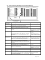
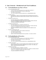
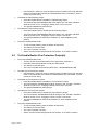
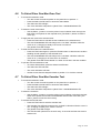
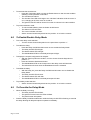
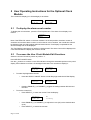
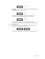
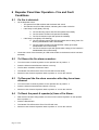
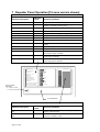
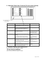
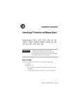
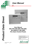
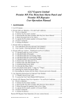
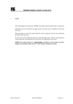
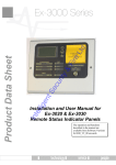
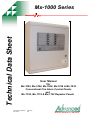
Technical Data Sheet
Mx-1000 Series
User Manual
for
Mx-1002, Mx-1004, Mx-1008, Mx-1016 & Mx-1032
Conventional Fire Alarm Control Panels
and
Mx-1108, Mx-1116 & Mx-1132 Repeater Panels
Document Number:
Revision:
680-072
02
ELECTRONICS LIMITED
1 Table of Contents
1
TABLE OF CONTENTS ......................................................................................................................2
2
USER OPERATION - FIRE AND FAULT CONDITIONS ..............................................................4
2.1
2.2
2.3
2.4
2.5
2.6
2.7
3
IF A FIRE IS DETECTED: .....................................................................................................................4
TO SILENCE THE FIRE ALARM SOUNDERS:.........................................................................................4
TO RESOUND THE FIRE ALARM SOUNDERS AFTER THEY HAVE BEEN SILENCED:................................4
TO RESET THE PANEL FROM A FIRE ALARM: ....................................................................................4
TO OPERATE THE FIRE ALARM SOUNDERS IN EVACUATE MODE: ......................................................5
IF A FAULT IS DETECTED: ..................................................................................................................5
TO SILENCE THE BUZZER: ................................................................................................................5
USER INDICATIONS AND CONTROLS..........................................................................................6
3.1
3.2
4
USER INDICATIONS [SHOWING OPTIONAL CLOCK MODULE]..............................................................6
USER CONTROLS [SHOWING OPTIONAL CLOCK MODULE] .................................................................7
USER CONTROLS – DISABLEMENT AND TEST CONDITIONS...............................................8
4.1
4.2
4.3
4.4
4.5
4.6
4.7
4.8
4.9
4.10
4.11
4.12
5
TO DISABLE/ENABLE ANY ZONE OR ZONES. ....................................................................................8
TO DISABLE/ENABLE ALL SOUNDERS...............................................................................................8
TO DISABLE/ENABLE THE FIRE ROUTING OUTPUT. ..........................................................................9
TO DISABLE/ENABLE THE FAULT ROUTING OUTPUT........................................................................9
TO DISABLE/ENABLE FIRE PROTECTION OUTPUT[S]. .....................................................................10
TO SELECT/CLEAR ONE MAN ZONE TEST. .....................................................................................11
TO SELECT/CLEAR ONE MAN SOUNDER TEST................................................................................11
TO ENABLE/DISABLE DELAY MODE ..............................................................................................12
TO OVERRIDE THE DELAY MODE ...................................................................................................12
TO EXTEND THE DELAY [FROM 1ST STAGE TO 2ND STAGE]...............................................................13
SILENCING THE ALARMS DURING THE DELAY: ..............................................................................13
RESOUNDING THE ALARMS AFTER THE DELAY: [ALARMS PREVIOUSLY SILENCED] .......................13
USER OPERATING INSTRUCTIONS FOR THE OPTIONAL CLOCK MODULE.................14
5.1
5.2
6
TO DISPLAY THE ALARM EVENT COUNTER ......................................................................................14
TO ACCESS THE USER CLOCK MODULE EDIT FUNCTIONS ..............................................................14
REPEATER PANEL USER OPERATION - FIRE AND FAULT CONDITIONS .......................16
6.1
6.2
6.3
6.4
6.5
6.6
6.7
IF A FIRE IS DETECTED: ...................................................................................................................16
TO SILENCE THE FIRE ALARM SOUNDERS:.......................................................................................16
TO RESOUND THE FIRE ALARM SOUNDERS AFTER THEY HAVE BEEN SILENCED:..............................16
TO RESET THE PANEL & REPEATER(S) FROM A FIRE ALARM:.........................................................16
TO OPERATE THE FIRE ALARM SOUNDERS IN EVACUATE MODE: ....................................................17
IF A FAULT IS DETECTED: ................................................................................................................17
TO SILENCE THE BUZZER: ..............................................................................................................17
7
REPEATER PANEL OPERATION [16 ZONE VERSION SHOWN]...........................................18
8
REPEATER PANEL USER CONTROLS [16 ZONE PANEL SHOWN] ......................................19
9
ROUTINE TESTING AND MAINTENANCE.................................................................................19
10
USER RESPONSIBILITIES .......................................................................................................... 19
11
ISOLATE/DE-ISOLATE/TEST MODE SELECT FLOWCHART ...........................................20
Moorland House : Nelson Park : Cramlington
Northumberland : NE23 1WE
Tel: +44 (0)1670 707 111
Fax: +44 (0)1670 707 222
www.Advel.co.uk Email: Sales@Advel.co.uk
ISO9001
ISO9001
Mx-1000 Series
Danger
This equipment contains hazardous voltages that can cause death, serious personal
injury, or equipment damage.
This equipment contains no user serviceable parts. Refer all maintenance to suitably
qualified personnel.
Page 3 of 20
2 User Operation - Fire and Fault Conditions
2.1
If a fire is detected:
•
On the Fire Alarm Panel:
o The general Fire LED will flash and the buzzer will sound
o The relevant zone Fire LED will flash, indicating the location of the fire.
o If the Delay is OFF [Delay LED off]:
The Fire Routing output and LED will operate immediately
The Fire Alarm sounders will operate immediately
The Fire Protection output will operate immediately
o If the Delay is ON [Delay LED flashing]:
The Fire Routing output and LED will operate after a delay [if the Fire
Routing fault/disabled LED is illuminated].
The Fire Alarm sounders will operate after a delay [if Sounder
fault/disabled LED is illuminated].
The Fire Protection output will operate after a delay [if Fire Protection
fault/disabled LED is illuminated].
•
Locate the source of the fire alarm (an LED will be visible on the detector which has been
activated).
2.2
To Silence the fire alarm sounders:
•
Turn the Access Controls Keyswitch on the panel door to position “1”.
•
Press the Silence Alarms/Resound button once only.
•
The fire alarm sounders will become silent.
•
The General Fire LED and the Zone Fire LED will become steady.
•
Set the Access Controls Keyswitch back to position “0” to lock the controls.
2.3
To Resound the fire alarm sounders after they have been
silenced:
•
Turn the Access Controls Keyswitch on the panel door to position “1”.
•
Press the Silence Alarms/Resound button once only.
•
Set the Access Controls Keyswitch back to position “0” to lock the controls.
2.4
To Reset the panel from a Fire Alarm:
•
After the fire has been extinguished, turn the Access Controls Keyswitch on the panel
door to position “1”.
•
Press the Reset button.
•
The General Fire LED and the Zone Fire LED will clear.
•
Set the Access Controls Keyswitch back to position “0” to lock the controls.
Page 4 of 20
2.5
To operate the fire alarm sounders in Evacuate Mode:
•
Turn the Access Controls Keyswitch on the panel door to position “1”.
•
Press the Evacuate button.
•
The Evacuate LED will light and the panel buzzer will operate.
•
All fire alarm sounders will operate.
•
Press the Silence/Resound Alarm button to silence the fire alarm sounders and clear the
Evacuate LED.
•
Set the Access Controls Keyswitch back to position “0” to lock the controls.
2.6
If a fault is detected:
•
The panel buzzer will sound.
•
The General Fault LED will flash.
•
One or more fault LEDs will flash; identifying which element of the system is faulty.
•
When the fault is corrected the fault indication will clear automatically unless the panel is
configured to latched fault mode – in which case, operating the Reset button will clear the
fault indication.
2.7
To Silence the Buzzer:
•
Press the Silence Buzzer button.
•
The Silence Buzzer button LED will light.
•
The buzzer will silence.
Page 5 of 20
3 User Indications and Controls
This section gives an overview of the functions available to the end user.
3.1
User Indications [showing optional clock module]
General Indicator Section
Indicator Description
Colour
Operating Condition
Power Supply On
Green
Steady indication for Mains or Standby power On.
Fire
Red
Flashes on any new fire alarm condition, changing to a steady
indication on operation of Silence Alarms.
Fire Routing Active
Red
Steady indication when the Fire Routing Output is active.
General Fault
Yellow
Flashes for any fault condition.
Power Supply Fault
Yellow
Flashes for mains or standby power supply/charge fault
System Fault
Yellow
Steady indication to indicate Microcontroller or Memory Failure.
Flashes to indicate Engineer’s Configuration Mode active.
Earth Fault
Yellow
Flashes for any positive or negative power supply earth fault.
Fuse Fault
Yellow
Flashes for any auxiliary supply fuse failure
Repeater Fault
Yellow
Flashes for any Repeater fault or repeater communication fault,
Sounder Fault/Disabled
Yellow
Flashes for any sounder fault. Steady for sounders disabled.
Sounder Test
Yellow
Steady indication while sounder walk test is active.
Fire Protection Fault/Disabled
Yellow
Flashes for a fault on the Fire Protection Output. Steady when Fire
Protection Output is disabled.
Fire Routing Fault/Disabled
Yellow
Flashes for a fault on the Fire Routing Output. Steady when Fire
Routing Output is disabled.
Fault Routing Fault/Disabled
Yellow
Flashes for a fault on the Fault Routing Output. Steady when Fault
Routing Output is disabled.
POWER SUPPLY ON
ZONE LOCATION
EVACUATE
FIRE
FIRE ROUTING ACTIVE
GENERAL FAULT
POWER SUPPLY FAULT
SYSTEM FAULT
TEST DISPLAY
SILENCE/
RESOUND
ALARMS
ENABLE
RESET
DISABLE
EARTH FAULT
FUSE FAULT
SILENCE
BUZZER
REPEATER FAULT
SOUNDER FAULT/DISABLED
DELAY
ON/OFF/
OVERRIDE
SOUNDER TEST
FIRE PROTECTION FAULT/DISABLED
TEST
SELECT
SELECT
ON/OFF
FIRE ROUTING FAULT/DISABLED
FAULT ROUTING FAULT/DISABLED
0
1
ZONE LOCATION
1
17
2
18
3
19
4
20
5
21
6
22
7
23
8
24
9
25
10
26
11
27
12
28
13
29
14
30
15
31
16
32
21 : 18 : 05
D / N OFF
Access Controls Keyswitch:
0 – Controls Locked
1 – Controls Unlocked
Clock Module [Optional]:
Showing time and Day/Night off
Back light flashes for Clock
Module fault.
User Instructions
Zone Location Indications
Indicator Description
Colour
Operating Condition
User Generated Zone Location Text
Red
Flashes when zone is in a fire condition, turning to steady on
operation of Silence Alarms.
User Generated Zone Location Text
Yellow
Flashes when zone is in a fault condition. Illuminates steady
when zone is disabled or in test.
Page 6 of 20
3.2
User Controls [showing optional clock module]
POWER SUPPLY ON
ZONE LOCATION
EVACUATE
FIRE
FIRE ROUTING ACTIVE
GENERAL FAULT
POWER SUPPLY FAULT
SYSTEM FAULT
TEST DISPLAY
SILENCE/
RESOUND
ALARMS
ENABLE
RESET
DISABLE
EARTH FAULT
FUSE FAULT
SILENCE
BUZZER
REPEATER FAULT
SOUNDER FAULT/DISABLED
DELAY
ON/OFF/
OVERRIDE
SOUNDER TEST
FIRE PROTECTION FAULT/DISABLED
TEST
SELECT
SELECT
ON/OFF
FIRE ROUTING FAULT/DISABLED
FAULT ROUTING FAULT/DISABLED
0
1
ZONE LOCATION
1
17
2
18
3
19
4
20
5
21
6
22
7
23
8
24
9
25
10
26
11
27
12
28
13
29
14
30
15
31
16
32
21 : 18 : 05
D / N OFF
Access Controls Keyswitch:
0 – Controls Locked
1 – Controls Unlocked
Switch
Description
Functionality
Button Availability
Evacuate
Operates all sounders continuously and lights the Evacuated LED
adjacent the button until the silence button is operated
When controls are unlocked
Silence/Resound
Alarms
Following a fire alarm condition, 1st operation stops sounders. The
General Fire LED and the Zonal fire LED will change from flashing to
steady. 2nd operation restarts the previously silenced sounders
When controls are unlocked
Reset
Clears the panel display, resets the zones, outputs and operates the
reset relay.
When controls are unlocked and [if
silence before reset is configured]
alarms silence switch has been
operated.
Silence Buzzer
1] Press to stop the buzzer sounding in fire or fault conditions.
When controls are locked or
unlocked
2] In 2 Stage Delay Mode, with stage 1 delay running, press to start
stage 2 delay otherwise all delayed outputs operate when Stage 1
timer times out.
When the panel is in the fire
condition and the delay is running.
Controls are locked or unlocked
1] Press once to Enable the delay mode, lighting the adjacent delay on
LED. Press again to disable the delay mode and turn off the LED
1] When controls are unlocked and
delay period is set to a value > 0.
2] Overrides the delay when delay is running, turning the delay mode
and the LED off. All delayed outputs will operate immediately.
2] When the panel is in the fire
condition and the delay is running.
Select On/Off
Enables the User select feature [Select ↑ Select ↓] for selection of
zones or outputs via for disablement/re-enablement and also
Day/Night On/Off selection and setting current time on clock module
(when fitted).
When controls are unlocked
Test Display
Press to illuminates all LEDs on the display and operate the buzzer. All
indications remain active for approx 5 seconds after button release.
Also displays alarm counter on clock module (when fitted).
When controls are locked or
unlocked
Enable
Press to clear the disablement or test condition on a zone or output
selected via the User Select feature.
When controls are unlocked, the
Select switch has been operated
and a zone or output has been
selected.
Disable
Press to disable a zone or output selected via the User Select feature.
As above.
Test
Press to initiate the One Man Test on sounders or zones as selected
via the User Select feature.
As above.
Select ↑ Select ↓
Used to scroll the cursor indication through the zone and output fault
LEDs on the display to select a zone or output for disablement, or test.
[LED illuminated when Select Mode is active]. Also scrolls through
clock module menu (when fitted).
When controls are unlocked and
the Select switch has been
operated.
Delay
On/Off/Override
Page 7 of 20
4 User Controls – Disablement and Test Conditions.
4.1
To Disable/Enable any Zone or Zones.
•
To Access disable/enable mode:
o Turn the Access Controls Keyswitch on the panel door to position “1”.
o Press the Select On/Off button to enter the Select Mode:
o The Select On LED will light.
o The cursor indication will pulse the yellow Zone 1 fault/disabled/test LED.
•
To select the zone:
o Use the Select ↓ button to move the pulsed cursor indication down through the
fault LEDs until it pulses the required zone. [The Select ↑ button moves the cursor
up].
•
To disable the selected zone:
o Press the Disable button to disable the selected zone.
o The zone fault/disabled LED will change to the “On-flash” indication while the
cursor is on it, changing to steady if the cursor is moved on.
o The general Disablement LED will light.
•
To enable the selected zone:
o Press the Enable button to enable the selected zone.
o The zone fault/disabled LED will change to the “Off-flash” indication while the
cursor is on it, changing to off if the cursor is moved on.
o The general Disablement LED will be cleared if no other disablements are
present.
•
To quit the disable/enable mode:
o To exit the Select Mode, press the Select On/Off button.
o The Select On LED will clear.
o The cursor indication will clear.
o Set the Access Controls Keyswitch back to position “0” to lock the controls.
4.2
To Disable/Enable all Sounders.
•
To Access disable/enable mode:
o Turn the Access Controls Keyswitch on the panel door to position “1”.
o Press the Select On/Off button to enter the Select Mode:
o The Select On LED will light.
o The cursor indication will pulse the yellow Zone 1 fault/disabled/test LED.
•
To select the sounders:
o Use the Select ↑ button to move the pulsed cursor indication up through the fault
LEDs until it pulses the Sounder Fault/Disabled and Sounder Test LEDs. [The
Select ↓ button moves the cursor down].
•
To disable the sounders:
o Press the Disable button to disable the sounders.
o The Sounder Fault/Disabled LED will change to the “On-flash” indication while the
cursor is on it, changing to steady if the cursor is moved.
o The general Disablement LED will light.
Page 8 of 20
•
To enable the sounders:
o Press the Enable button to enable the sounders.
o The Sounder Fault/Disabled LED will change to the “Off-flash” indication while the
cursor is on it, changing to off if the cursor is moved on.
o The general Disablement LED will be cleared if no other disablements are
present.
•
To quit the disable/enable mode:
o To exit the Select Mode, press the Select On/Off button.
o The Select On LED will clear.
o The cursor indication will clear.
o Set the Access Controls Keyswitch back to position “0” to lock the controls.
4.3
To Disable/Enable the Fire Routing Output.
•
To Access disable/enable mode:
o Turn the Access Controls Keyswitch on the panel door to position “1”.
o Press the Select On/Off button to enter the Select Mode:
o The Select On LED will light.
o The cursor indication will pulse the yellow Zone 1 fault/disabled/test LED.
•
To select the Fire Routing Output:
o Use the Select ↑ button to move the pulsed cursor indication up through the fault
LEDs until it pulses the Fire Routing Fault/Disabled LED. [The Select ↓ button
moves the cursor down].
•
To disable the Fire Routing Output:
o Press the Disable button to disable the Fire Routing Output.
o The Fire Routing Fault/Disabled LED will change to the “On-flash” indication while
the cursor is on it, changing to steady if the cursor is moved.
o The general Disablement LED will light.
•
To enable the Fire Routing Output:
o Press the Enable button to enable the Fire Routing Output.
o The Fire Routing Fault/Disabled LED will change to the “Off-flash” indication while
the cursor is on it, changing to off if the cursor is moved on.
o The general Disablement LED will be cleared if no other disablements are
present.
•
To quit the disable/enable mode:
o To exit the Select Mode, press the Select On/Off button.
o The Select On LED will clear.
o The cursor indication will clear.
o Set the Access Controls Keyswitch back to position “0” to lock the controls.
4.4
To Disable/Enable the Fault Routing Output.
•
To Access disable/enable mode:
o Turn the Access Controls Keyswitch on the panel door to position “1”.
o Press the Select On/Off button to enter the Select Mode:
o The Select On LED will light.
o The cursor indication will pulse the yellow Zone 1 fault/disabled/test LED.
•
To select the Fault Routing Output:
Page 9 of 20
o
Use the Select ↑ button to move the pulsed cursor indication up through the fault
LEDs until it pulses the Fault Routing Fault/Disabled LED. [The Select ↓ button
moves the cursor down].
•
To disable the Fault Routing Output:
o Press the Disable button to disable the Fault Routing Output.
o The Fault Routing Fault/Disabled LED will change to the “On-flash” indication
while the cursor is on it, changing to steady if the cursor is moved.
o The general Disablement LED will light.
•
To enable the Fault Routing Output:
o Press the Enable button to enable the Fault Routing Output.
o The Fault Routing Fault/Disabled LED will change to the “Off-flash” indication
while the cursor is on it, changing to off if the cursor is moved on.
o The general Disablement LED will be cleared if no other disablements are
present.
•
To quit the disable/enable mode:
o To exit the Select Mode, press the Select On/Off button.
o The Select On LED will clear.
o The cursor indication will clear.
o Set the Access Controls Keyswitch back to position “0” to lock the controls.
4.5
To Disable/Enable Fire Protection Output[s].
•
To Access disable/enable mode:
o Turn the Access Controls Keyswitch on the panel door to position “1”.
o Press the Select On/Off button to enter the Select Mode:
o The Select On LED will light.
o The cursor indication will pulse the yellow Zone 1 fault/disabled/test LED.
•
To select the Fire Protection Output:
o Use the Select ↑ button to move the pulsed cursor indication up through the fault
LEDs until it pulses the Fire Protection Fault/Disabled LED. [The Select ↓ button
moves the cursor down].
•
To disable the Fire Protection Output:
o Press the Disable button to disable the Fire Protection Output.
o The Fire Protection Fault/Disabled LED will change to the “On-flash” indication
while the cursor is on it, changing to steady if the cursor is moved.
o The general Disablement LED will light.
•
To enable the Fire Protection Output:
o Press the Enable button to enable the Fire Protection Output.
o The Fire Protection Fault/Disabled LED will change to the “Off-flash” indication
while the cursor is on it, changing to off if the cursor is moved on.
o The general Disablement LED will be cleared if no other disablements are
present.
•
To quit the disable/enable mode:
o To exit the Select Mode, press the Select On/Off button.
o The Select On LED will clear.
o The cursor indication will clear.
o Set the Access Controls Keyswitch back to position “0” to lock the controls.
Page 10 of 20
4.6
To Select/Clear One Man Zone Test.
•
To access test selection mode:
o Turn the Access Controls Keyswitch on the panel door to position “1”.
o Press the Select On/Off button to enter the Select Mode:
o The Select On LED will light.
o The cursor indication will pulse the yellow Zone 1 fault/disabled/test LED.
•
To select the zone to be tested:
o Use the Select ↓ button to move the pulsed cursor indication down through the
fault LEDs until it pulses on the required zone. [The Select ↑ button moves the
cursor up].
•
To apply the test mode to the selected zone:
o Press the Test button to activate the test condition on the selected zone.
o The zone fault/disabled LED will change to the “On-flash” indication while the
cursor is on it, changing to steady if the cursor is moved on.
o The general Test LED will light.
•
To clear the test mode on the selected zone:
o Press the Test button again or press the Enable button to clear the test condition
enabling normal operation of the selected zone.
o The zone fault/disabled LED will change to the “Off-flash” indication while the
cursor is on it, changing to off if the cursor is moved on.
o The general Test LED will be cleared if no other circuits are in the test condition.
•
To quit the zone test selection mode:
o To exit the Select Mode, press the Select On/Off button.
o The Select On LED will clear.
o The cursor indication will clear.
o Set the Access Controls Keyswitch back to position “0” to lock the controls.
4.7
To Select/Clear One Man Sounder Test.
•
To access test selection mode:
o Turn the Access Controls Keyswitch on the panel door to position “1”.
o Press the Select On/Off button to enter the Select Mode:
o The Select On LED will light.
o The cursor indication will pulse the yellow Zone 1 fault/disabled/test LED.
•
To select the sounders:
o Use the Select ↑ button to move the pulsed cursor indication up through the fault
LEDs until it pulses the Sounder Fault/Disabled and Sounder Test LEDs. [The
Select ↓ button moves the cursor down].
•
To activate the sounder test:
o Press the Test button to start the sounder test.
o The Sounder Test LED will change to the “On-flash” indication while the cursor is
on it, changing to steady if the cursor is moved.
o The general Test LED will light.
o The sounders will operate for 2 seconds every 15 seconds until the test mode is
switched off.
Page 11 of 20
•
To terminate the sounder test:
o Press the Test button again or press the Enable button to clear the test condition
enabling normal operation of sounders.
o The sounders will silence.
o The Sounder Test LED will change to the “Off-flash” indication while the cursor is
on it, changing to off if the cursor is moved on.
o The general Test LED will be cleared if no other circuits are in the test condition.
•
To quit test selection mode:
o To exit the Select Mode, press the Select On/Off button.
o The Select On LED will clear.
o The cursor indication will clear.
o Set the Access Controls Keyswitch back to position “0” to lock the controls.
4.8
To Enable/Disable Delay Mode
•
To access delay mode selection:
o Turn the Access Controls Keyswitch on the panel door to position “1”.
•
To enable the delay:
o Press the Delay On/Off/Override button once to enable the Delay Mode.
o The Delay On/Off LED will light.
o The disable switch LED will light.
o The fault/disabled LED for each delayed output will light.
•
To display the outputs configured to be delayed:
o With the panel in quiescent condition, turn the Access Controls Keyswitch to
position “1”.
o Press and hold the disablement button.
o The fault/disabled LED on each output set to the delay mode will illuminate.
o The indications will clear when the Disablement button is released.
•
To disable the delay:
o With the Delay On, press the Delay On/Off/Override button once to disable the
Delay Mode.
o The Delay On/Off LED will clear.
o The disable switch LED will clear.
o The fault/disabled LED for each delayed output will clear.
•
To quit delay mode selection:
o Set the Access Controls Keyswitch back to position “0” to lock the controls.
4.9
To Override the Delay Mode
•
When the Delay is running:
o The Delay On/Off LED will flash.
o The general Fire and zone fire LEDs will flash.
o The panel buzzer will operate.
•
Press the Delay On/Off/Override button while the Delay On/Off LED is flashing to override
the delay allowing all delayed outputs to operate immediately.
Page 12 of 20
4.10 To Extend the Delay [from 1st stage to 2nd Stage]
•
When the panel is configured to the two stage delay mode and before 60 seconds has
elapsed since the fire alarm triggered:
o Press the Silence Buzzer button.
o The Silence Buzzer button LED will light.
The buzzer will silence.
The 2nd stage delay will start.
4.11 Silencing the Alarms During the Delay:
•
Turn the Access Controls Keyswitch on the panel door to position “1”.
•
Press the Silence Alarms/Resound button.
o The General Fire LED and the Zone Fire LED become steady.
o The sounders will not operate after the delay has timed out.
•
Set the Access Controls Keyswitch back to position “0” to lock the controls.
4.12 Resounding the Alarms after the Delay: [Alarms previously
silenced]
•
Turn the Access Controls Keyswitch on the panel door to position “1”.
•
Press the Silence Alarms/Resound button.
o The General Fire LED will flash.
o The sounders operate.
•
Set the Access Controls Keyswitch back to position “0” to lock the controls.
Page 13 of 20
5 User Operating Instructions for the Optional Clock
Module
The normal time display (no LCD backlight) is as follows:
HH:MM:SS
D/N ON
5.1
or
HH:MM:SS
D/N OFF
To display the alarm event counter
To display the currrent alarm , press the Test Displat button. The Alarm Count display is as
follows:
ALARMS:NNNN
Note: If the ZERO DIL switch on the timer module is in the ON position, the alarm counter is
cleared to zero and the alarm counter is not functional. In this condition, the normal time will still
be displayed and the LCD backlight will illuminate when the Test Display is operated but the
above message will not be displayed.
The Test Display button does not need to be held pressed. The Alarm Count will be displayed for
5 seconds and then the display will revert to normal.
5.2
To access the User Clock Module Edit Functions
Select the Access Control key switch to position “1”.
Press SELECT ON/OFF button.
Use the ↑↓ buttons to scroll the cursor LED indication through the selectable options on the panel
display LED indications until the LCD backlight illuminates. The normal time display is:
HH:MM:SS
D/N ON
•
HH:MM:SS
D/N OFF
To select Day/Night Mode On/Off:
o Press the SELECT ON/OFF button to enter Day/night mode On/Off Set Display:
D/N ON
Change?
o
•
or
or
D/N OFF
Change?
Pressing ENABLE (+) or DISABLE (-) toggles the setting between D/N ON and
D/N OFF.
To set the current time:
o Press SELECT ↓ to enter the current Time Set Display:
HH:MM:SS
Time Set
o
o
Page 14 of 20
HH
flashing
Press ENABLE (+) or DISABLE (-) to adjust the hours (HH) to the desired value
(0-23).
Press SELECT ↓ to select the minutes:
HH:MM:SS
Time Set
o
o
MM
flashing
Press ENABLE (+) or DISABLE (-) to adjust the minutes (MM) to the desired
value (0-59).
Press SELECT ↓ to select the seconds:
HH:MM:SS
Time Set
o
o
SS
flashing
Press ENABLE (+) or DISABLE (-) to reset the seconds (SS) to zero.
Press SELECT ↓ to exit to the Day/Night Mode On/Off Set Display:
D/N OFF
Change?
D/N ON
Change?
Pressing SELECT ↓ repeates the cursor/display changes as above.
Pressing SELECT ↑ repeates the cursor/display changes as above in reverse.
•
To exit Clock Module Menu:
o Press SELECT ON/OFF: Module switches off the LCD backlight and exits
configuration mode. The normal time display is:
HH:MM:SS
D/N ON
o
or
HH:MM:SS
D/N OFF
On completion of editing, return the Access Control key switch to position “0”.
Page 15 of 20
6 Repeater Panel User Operation - Fire and Fault
Conditions
6.1
If a fire is detected:
•
On the Repeater Panel:
o The general Fire LED will flash and the buzzer will sound
o The relevant zone Fire LED will flash, indicating the location of the fire.
o If the Delay is OFF [Delay LED off]:
The Fire Routing output and LED will operate immediately
The Fire Alarm sounders will operate immediately
The Fire Protection output will operate immediately
o If the Delay is ON [Delay LED flashing]:
The Fire Routing output and LED will operate after a delay [if the Fire
Routing fault/disabled LED is illuminated].
The Fire Alarm sounders will operate after a delay [if Sounder
fault/disabled LED is illuminated].
The Fire Protection output will operate after a delay [if Fire Protection
fault/disabled LED is illuminated].
•
Locate the source of the fire alarm (an LED will be visible on the detector which has been
activated).
6.2
To Silence the fire alarm sounders:
•
Turn the Access Controls Keyswitch on the repeater door to position “1”.
•
Press the Silence Alarms/Resound button once only.
•
The fire alarm sounders will become silent.
•
The General Fire LED and the Zone Fire LED will become steady.
•
Set the Access Controls Keyswitch back to position “0” to lock the controls.
6.3
To Resound the fire alarm sounders after they have been
silenced:
•
Turn the Access Controls Keyswitch on the repeater door to position “1”.
•
Press the Silence Alarms/Resound button once only.
•
Set the Access Controls Keyswitch back to position “0” to lock the controls.
6.4
To Reset the panel & repeater(s) from a Fire Alarm:
•
After the fire has been extinguished, turn the Access Controls Keyswitch on the repeater
door to position “1”.
•
Press the Reset button.
•
The General Fire LED and the Zone Fire LED will clear.
•
Set the Access Controls Keyswitch back to position “0” to lock the controls.
Page 16 of 20
6.5
To operate the fire alarm sounders in Evacuate Mode:
•
Turn the Access Controls Keyswitch on the repeater door to position “1”.
•
Press the Evacuate button.
•
The Evacuate LED will light and the repeater buzzer will operate.
•
All fire alarm sounders will operate.
•
Press the Silence/Resound Alarm button to silence the fire alarm sounders and clear the
Evacuate LED.
•
Set the Access Controls Keyswitch back to position “0” to lock the controls.
6.6
If a fault is detected:
•
The repeater buzzer will sound.
•
The General Fault LED will flash.
•
One or more fault LEDs will flash; identifying which element of the system is faulty.
•
When the fault is corrected the fault indication will clear automatically unless the panel is
configured to latched fault mode – in which case, operating the Reset button will clear the
fault indication.
6.7
To Silence the Buzzer:
•
Press the Silence Buzzer button.
•
The Silence Buzzer button LED will light.
•
The buzzer will silence.
Page 17 of 20
7 Repeater Panel Operation [16 zone version shown]
General Indicator Section
Indicator Description
Indication
Colour
Power Supply On
Green
Steady indication for Mains or Standby power On.
Fire
Red
Flashes on any new fire alarm condition, changing to a steady
indication on operation of Silence Alarms.
Fire Routing Active
Red
Steady indication when the Fire Routing Output is active.
General Fault
Yellow
Flashes for any fault condition.
Power Supply Fault
Yellow
Flashes for mains or standby power supply/charge fault
System Fault
Yellow
Steady indication to indicate Microcontroller Failure.
General Test
Yellow
Steady indication when the zone or sounder test is active.
General Disablement
Yellow
Steady indication whilst a zone or output is disabled.
Communications Fault
Yellow
Flashes for a communications failure between the fire panel and
repeater.
Sounder Fault/Disabled
Yellow
Flashes for any sounder fault. Steady for sounders disabled.
Sounder Test
Yellow
Steady indication while sounder walk test is active.
Fire Protection Fault/Disabled
Yellow
Flashes for a fault on the Fire Protection Output. Steady when
Fire Protection Output is disabled.
Fire Routing Fault/Disabled
Yellow
Flashes for a fault on the Fire Routing Output. Steady when Fire
Routing Output is disabled.
Fault Routing Fault/Disabled
Yellow
Flashes for a fault on the Fault Routing Output. Steady when
Fault Routing Output is disabled.
Operating Condition
POWER SUPPLY ON
ZONE LOCATION
1
EVACUATE
FIRE
2
FIRE ROUTING ACTIVE
3
SILENCE/
RESOUND
ALARMS
GENERAL FAULT
POWER SUPPLY FAULT
SYSTEM FAULT
4
5
6
RESET
7
GENERAL TEST
GENERAL DISABLEMENT
COMMUNICATIONS FAULT
SOUNDER FAULT/DISABLED
SOUNDER TEST
8
SILENCE
BUZZER
9
10
11
DELAY
ON/OFF/
OVERRIDE
12
13
FIRE PROTECTION FAULT/DISABLED
Access Controls
Keyswitch:
0 – Controls Locked
1 – Controls Unlocked
FIRE ROUTING FAULT/DISABLED
14
TEST DISPLAY
15
FAULT ROUTING FAULT/DISABLED
0
16
1
User Instructions
Zone Location Indications
Indicator Description
Indication
Colour
Operating Condition
User Generated Zone Location
Text
Red
Flashes when zone is in a fire condition, turning to steady on
operation of Silence Alarms.
User Generated Zone Location
Text
Yellow
Flashes when zone is in a fault condition. Illuminates steady
when zone is disabled or in test.
Page 18 of 20
8 Repeater Panel User Controls [16 zone panel shown]
POWER SUPPLY ON
ZONE LOCATION
1
EVACUATE
FIRE
FIRE ROUTING ACTIVE
GENERAL FAULT
POWER SUPPLY FAULT
SYSTEM FAULT
2
3
SILENCE/
RESOUND
ALARMS
4
5
6
RESET
7
EARTH FAULT
FUSE FAULT
REPEATER FAULT
SOUNDER FAULT/DISABLED
SOUNDER TEST
8
SILENCE
BUZZER
DELAY
ON/OFF/
OVERRIDE
FIRE PROTECTION FAULT/DISABLED
FIRE ROUTING FAULT/DISABLED
TEST DISPLAY
FAULT ROUTING FAULT/DISABLED
0
9
10
11
12
13
14
15
16
1
Access Controls Keyswitch:
0 – Controls Locked
1 – Controls Unlocked
Switch Description
Functionality
Button Availability
Evacuate
Operates all sounders continuously and lights the
Evacuated LED adjacent the button until the silence
button is operated
When controls are unlocked
Silence/Resound Alarms
Following a fire alarm condition, 1st operation stops
sounders. The General Fire LED and the Zonal fire
LED will change from flashing to steady. 2nd
operation restarts the previously silenced sounders
When controls are unlocked
Reset
Clears the panel display, resets the zones, outputs
and operates the reset relay.
When controls are unlocked
1] Press to stop the buzzer sounding in fire or fault
conditions.
When controls are locked or
unlocked
2] In 2 Stage Delay Mode, with stage 1 delay
running, press to start stage 2 delay otherwise all
delayed outputs operate when Stage 1 timer times
out.
When the panel is in the fire
condition and the delay is
running. Controls are locked or
unlocked
1] Press once to Enable the delay mode, lighting the
adjacent delay on LED. Press again to disable the
delay mode and turn off the LED
1] When controls are unlocked
and delay period is set to a
value > 0.
2] Overrides the delay when delay is running, turning
the delay mode and the LED off. All delayed outputs
will operate immediately.
2] When the panel is in the fire
condition and the delay is
running.
Press to illuminates all LEDs on the display and
operate the buzzer. All indications remain active for
approx 5 seconds after button release.
When controls are locked or
unlocked
Silence Buzzer
Delay On/Off/Override
Test Display
and [if silence before reset is
configured] alarms silence
switch has been operated.
9 Routine Testing and maintenance
Refer to the Mx-1000 Series Log Book for details.
10 User Responsibilities
Refer to the Mx-1000 Series Log Book for details.
Page 19 of 20
11 Isolate/De-isolate/Test Mode Select Flowchart
Controls not Enabled
CURSOR Sequence:
Turn ACCESS
CONTROLS
keyswtich to "1"
Zone 1 Fault LED
Zone 2 Fault LED
Controls Enabled
Zone Fault LED (n= 2,4,8,16,32
depending on panel)
Turn ACCESS
CONTROLS keyswitch to "0"
Sounder Fault/Disabled & Test LEDs
Press SELECT ON/OFF
button
Fire Protection Fault/Disabled LED
Fire Routing Fault/Disabled LED
Fault Routing Fault/Disabled LED
SELECT mode Active,
SELECT ON/OFF LED
illuminated
SELECT cursor flashes
Zone 1 Fault LED
Press SELECT ↓ button
SELECT cursor moves
to next LED
Page 20 of 20
Press SELECT ↑ button
SELECT cursor moves
to previous LED
Press ENABLE button
Press DISABLE button
Press TEST button
Selected Circuit returned
to normal operation.
LED pulses "OFF/flash"
(Changes to OFF when
cursor is removed)
Selected Circuit
Disabled..
Circuit LED pulses
"ON/flash" (Changes to
STEADY when cursor is
removed)
Selected Circuit in Test Mode.
If Zone then Zone Fault LED
pulses "ON/flash".
(Changes to steady when
cursor removed).
If Sounders then Sounder
TEST LED is ON.
Press SELECT ON/OFF
button
SELECT mode inactive.
SELECT cursor clears.
SELECT LED clears.