1
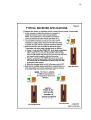
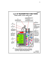
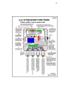
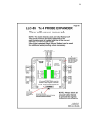
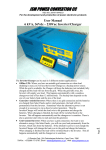
ABCO ELECTRONICS LLC-40 Liquid Level Controller User Manual Automatic Water Filling of Storage Tanks Several Km Reliable Radio Control Range Solar Charged Transmitter at Tanks Simple Installation Extremely Versatile System Control of Several Water Tanks Unlimited Pumps at different locations Cycling feature for “Weak” Boreholes Early warning Flood monitoring of Rivers Etc. 2 LLC-40 Liquid Level Controller Index Page 1 Packing List Page 2 General Description Page 5 Transmitter Installation Instructions Page 8 Receiver Installation Instructions Page 11 Setting the Receiver Operating modes and setting the Digital Timer Page 12 Operation of the No Flow Safety Circuit Page 13 Transmitter Battery replacement Page A1 Typical Transmitter Installations Page A2 Typical Receiver Installations Page A3 Transmitter Functions – Internal Layout Internal diagram of Jumpers and Battery etc. Page A4 Receiver Functions – Internal Layout Internal diagram of Indicators and Controls Page A5 Transmitter Expander – Internal Layout Internal diagram ABCO Electronics Pietermaritzburg Tel: 033-343-2903 South Africa Fax: 086 618 3157 3 LLC-40 Liquid Level Controller Packing List The following items are included in the LLC-40 Liquid Level Controller Kit: 1. Transmitter: a. 1 x LLC-40 Transmitter unit c/w Mounting Bracket b. 1 x LLC-40 Instruction Booklet a. 1 x Alan Key for securing aerial b. 2 x Aerial Tapered Whips (Shorter than Receiver Whip) c. 2 x 8mm Coach Screws for securing Transmitter to pole d. 1 x B-01/10 Float Switch for water level detection e. 4 x T18R Small Cable Ties f. 6 x T120L Large Cable Ties g. 1 x PG11 Cable Gland for securing Probe Lead Through Tank 2. Receiver: a. 1 x LLC-43 Receiver Module in plastic housing b. 1 x Wall Mount Bracket for aerial c. 2 x U-Bolts for attaching mast to aerial bracket d. 4 x M6 Expanding Bolts for bracket attachment to wall e. 4 x 5/36 Hilti Wall Plugs c/w Screws for mounting unit to wall f. 1 x Aerial Mast assembly g. 1 x 7.5 Meters length Aerial Co-axial Cable c/w Connector h. 1 x Aerial Tapered Whip (Longer than the Transmitter Whips) i. 1 x Alan Key for securing aerial j. 6 x T18R Small Cable Ties k. 4 x T501 Large Cable Ties l. 1 x 1 Meter Length 0.5mm 3 Core Grey PVC Cabtyre Cable m. 1 x 5 Meter Length 0.5mm 2 Core Grey PVC Cabtyre Cable n. 1 x LLC-50A Drilling Template for mounting Receiver to wall 3. Optional Extra: 4 Probe Expander for Transmitter: a. 1 x LLC-55 4 Probe Expander Module c/w mounting bracket b. 3 x B-01/10 Float Switches for water level detection c. 1 x 250mm Cable for connecting Expander to Transmitter END LLC-40 Liquid Level Controller 4 Instruction Manual General Description. The ABCO LLC-40 Liquid Level Controller is specifically designed to automatically control the filling of Water Storage Tanks without water wastage. Water Level sensing is accomplished with the use of a reliable and very robust Float Type switch. The Maximum and Minimum switching levels are readily set with an adjustment weight fitted to the connecting cord. Radio Signals couple the Transmitter which is located at the Water Tanks to the Receiver at the Pump. Several kilometers range between the Transmitter and pump is possible (dependant on geographical terrain). Note: A small Pole Mounted and Solar Powered Repeater unit is available from ABCO and is useful for rugged terrain applications. Batteries in the Transmitter are maintained in a charged condition by a very small Solar panel (120mm x 120mm). This Battery ensures continued and reliable operation for about 3 weeks in the event of no sunshine. Solar Panel orientation must be North facing and the standard mounting bracket is designed for fixing ideally to a Creosote pole. It is essential that the pole be of sufficient length to ensure that no shadows from trees or the Water Tanks themselves limit the available sunshine that reaches the Solar panel. A tall pole further discourages potential vandalism. Note: An AC Mains version of the Transmitter is available for those applications which have no sunshine available. Continuous signal re-transmissions from Transmitter to Pump at about 20 Minute intervals ensures system reliability. i.e. In the event of a signal being corrupted or lost as a result of interference or other means, the Receiver will be refreshed by the next signal. Features: Several design features incorporated within the system greatly enhance system versatility. The Water Levels of up to four Water Tanks each equipped with independent Sensing Probes can be coupled to a single Transmitter by using the LLC-55 Expander unit. Should any of the four Tanks register a low level status; the pump will be instructed to refill all the tanks. Several Receivers at various locations can be operated from a single Transmitter unit. Useful when several boreholes supply water to a common storage point. 5 The Receiver is extremely versatile and is simply programmed with the Front Panel switches to perform in one of five selectable Modes. The associated Timer is settable in the range from 10 to 635 Minutes in 5 Minutes increments. Mode 1 “TIMER OFF” selected on the Top Switch. All other Switch settings are bypassed when “TIMER OFF” is selected! The Pump Starts and Stops directly on demand from the Transmitter. NOTE: The No Flow safety circuit and the Time Clock inhibit functions remain fully functional when “TIMER OFF” is selected. Mode 2 “Single Run” and “Instant Start” selected. Results in a Timed Run period for applications where the Pump is required to immediately Start on receipt of Start command from the Transmitter, and then to Stop again after a pre-determined period as selected on the Timer. The pump cannot Start again until a Stop command and then a further Start command has been received from the Transmitter. This feature is useful when several pumps feed a common storage Tank using boreholes that have a limited water availability. Mode 3 “Single Run” and “Delay before Run” selected. Applications which use multiple Pumps at different locations to feed the same storage Tanks, can be set to start at varying times. i.e. Should the Main Pump not be able to fill the Tanks within a prescribed period (when there is excessive water demand from the Tanks), the second pump will start. This is extendable to as many pumps as may be required. Mode 4 “50% Cycle Mode” and “Delay before Run” selected. This is a very useful configuration for “Weak” boreholes which are unable to provide sustained water delivery. The Pump will cycle ON and OFF at a 50% rate as determined by the selected Time so as to prevent the borehole being depleted by continuous pumping. The initial Pump Start is delayed by the selected Time following receipt of the Start Command from the Transmitter. Mode 5 “50% Cycle Mode” and “Instant Start” selected. Identical to Mode 4 above except that the Pump Starts immediately on receipt of the Start Command from the Transmitter. Thereafter the Pump continues to cycle at a 50% ON and OFF rate as per the selected time until such a time as a Stop command is received from the Transmitter. Pump protection is provided on the Receiver whereby should no water flow be detected for approximately 30 Seconds, the Pump will be shut down. Re-starting cannot occur until the RESET switch is actuated or the AC Mains Power has been interrupted for a few seconds. Either Pressure or Water Flow switches can be used to determine that flow is present. This feature can be bypassed where necessary. 6 An Alarm output is provided which can be coupled to a warning device to indicate that the Pump has failed due to no Water Flow. For example, the use of a Cell Phone Tele-dialer will send an SMS signal to one or more Cell Phones alerting of the failure. This is extremely handy for critical water supplies e.g. Game Watering. NOTE: Abco can supply an alternate Transmission and Receiving equipment for areas where Cell Phone communication is unreliable or not practical. Erratic AC Mains recovery following a power failure is prevented by a feature that prevents an automatic Pump re-start until the next refresh signal is received from the Transmitter unit. Automatic shutting down of the Pump in the event of a faulty or damaged Transmitter unit. This occurs when no refresh signal is received at the pump for 30 Minutes. Facility is provided at the Pump to fit a Time Clock unit which is used to place the Pump on Hold during peak electricity supply hours. Advantage can therefore be taken of the lower “Off Peak” supply rates. A Useful Application. A further and useful application for the equipment is that of monitoring water level in rivers that are prone to occasional flooding. This is particularly relevant and cost effective when low lying pumping and irrigation equipment is subject to flood damage. END - General Description LLC-40 Liquid Level Controller Installation & Commissioning Instructions 7 This equipment has been designed manufactured to high standards! When installed with care and attention to detail, the system will provide many years of reliable use. Avoid taking short cuts and shoddy workmanship as these inevitably degrade the reliability of the installation. 1. The Transmitter unit located at the Water Tanks. You will need the following tools: 1. 1 x 10mm Ring/Open Set Spanner 2. 1 x 13mm Ring/Open Set Spanner 3. 1 x Battery operated Drill with following Drill Bits: a. 5.5mm Standard Drill Bit b. 18.5mm Speed Bore Bit (Type for wood or plastic) 4. 1 x Pair of Electricians Pliers with Cutters 5. 1 x Multi-meter with built in buzzer to measure continuity General considerations for optimum Transmitter placement: The Solar Powered Transmitter unit is designed to be Pole Mounted alongside the water Tanks which it controls. The pole must be of the creosote treated type and of sufficient length to ensure that the unit is positioned above shaded areas especially during the winter months. A long pole also provides additional protection against vandalism. The Solar Panel must positioned to face North, and the 30 degree angle from horizontal which is automatically provided by the stainless steel bracket, must not be compromised. i.e. The bracket must be secured to a vertical surface (pole)! Avoid locating the Transmitter beneath partly shaded tree cover etc. it may be necessary to cut back branches from trees to ensure the sunlight to the Solar Panel is not hindered. Caution: Branches grow over a period of time – check from time to time. Note that the cable attached to the water level sensing probe is 10 Meters in length. This must be taken into consideration when positioning the Transmitter as cable joints must be avoided. Installing the Transmitter 8 NOTE: Do Not connect the internal Battery until the rest of the installation has been completed! Failure to observe this could damage the Radio Transmitter Circuits! It is assumed that the Wooden Creosote pole has been installed. a. Fit and tighten the two SHORTER Tapered Aerial Whips to the receptacles on top of the Transmitter unit (the LONGER Whip is for use with the Receiver). Tighten firmly with the Alan Key provided in the kit. Loosen the 6mm Nut beneath the Antenna Bracket and rotate the assembly such that the two aerial whips are positioned to face at right angles to the direction of where the receiver Aerial at the Pump will be located. i.e. The whips must not be in line with the Receiver Aerial, but at right angles to it – by looking through the V formed by the whips, you must be looking in the general direction of the Pump House. Firmly tighten the 6mm Nut with the 10mm Spanner. b. Attach the Transmitter to the top of the pole using the two Coach screws provided for the purpose. Use the 5.5mm Drill Bit to drill the pilot holes for the screws and tighten with the 13mm Spanner. c. Install the Water Level Sensing probe in the Water Tank: Plastic Tanks: Drill an 18.5mm hole adjacent to the Tank Lid towards the centre of the Tank and fit the supplied PG11 Cable Gland through this hole with the large side facing outwards. Tighten the Hex Nut on the inside. Feed the sensing probe cable through this Cable Gland from the inside of the tank – the Probe will now be located inside the tank. Concrete and other Tanks: Locate a suitable place on the Tank Cover that is able to secure the Probe cable whilst leaving the associated weight hanging inside the Tank. It may be necessary to place a metal beam across the top of the Tank with an 18.5mm hole drilled through for the cable Gland. DO NOT CUT THE SENSOR CABLE! Connect the Multimeter to the ends of the Sensor Cable and set it to buzz whenever continuity is made. Adjust the weight position and height of the cable and Sensing Probe to achieve the desired switching points. A short length between the adjustable weight and sensor will achieve close switching points for the maximum and minimum water levels and visa versa. The Multimeter Buzzer will sound whenever the Sensor reaches the LOW water level. d. Securely locate the Cable from the Sensing Probe to the Transmitter unit using the Cable Ties provided. Roll up any unused cable and cable tie it to the Pole. Terminate the two ends 9 of the Cable into the two Terminals at the rear of the Transmitter plastic housing. There is a small hole through the side of each Terminal which can be located by unscrewing the plastic knurled nut on the connector. Fit the Probe wire ends to these Terminals by threading them through the above holes from the top side so as to ensure a long term tight fit. The polarity of the wires is not important and they can be connected either way around. Refer to the Drawing ‘Transmitter Functions” caption 12. e. Cable-tie the Sensor probe cable to pole behind the Transmitter at a point above the height of the two Terminals. This is to ensure that rain water cannot run down the inside of the wire insulation and damage the cable. Fit Cable Ties as necessary to secure the rest of the Cable. f. Remove the Cover from beneath the Transmitter and connect the Battery by plugging the Red Bullet Connectors together. NOTE: Observe Positive and Negative Polarity!!!!! g. Refer to the drawing “Transmitter Functions” and note the Jumper associated with caption 2 “BUZZER”. Set this to ON. Manually lift and lower the Level sensing Probe and note that the Buzzer responds to the UPPER and LOWER changes within a few seconds of them occurring. This confirms that the Transmitter unit is functioning correctly. NOTE: Wait about 10 seconds at each switching limit of the Probe before changing its status! h. Fit the cover back in place taking care that it does not foul the Battery Leads. These need to be gently snug fitted in between the Battery and the side of the Plastic Casing. NOTE: The two Black Atmospheric Breather Plugs on the Cover Lid must be positioned so as to be located at the lowest part of the Lid away from the Creosote Pole. These plugs must always be fitted and pressed into place on the Lid. Omitting them will permit insects to gain access to the electronics!! i. The Battery is designed to provide several years’ service before replacement becomes necessary. The customer is encouraged to check the Solar panel from time to time and clean off excess bird droppings etc. A poorly charged battery will greatly reduce its life span!! Battery replacement is self explanatory once the cover has been removed. NOTE: The internal Buzzer is designed to Buzz for a few seconds every 20 minutes. The idea is to deter and chase birds away from settling on the Solar Panel. 10 The Buzzer will also sound every time a Data Transmission to the Pump Receiver occurs. i.e. whenever the Sensing Probe senses a change in Water Level, as well as every 20 Minutes as a confirmation signal is Transmitted to the Receiver. The Buzzer can be disabled by selecting OFF on the BUZZER Jumper which is located inside the Transmitter unit. Refer Caption 4 on the Transmitter Functions Drawing. Installing the Receiver Unit Located at the Pump You will need the following tools: 1. 2. 3. 4. 5. 1 x 13mm Ring/Open Set Spanner 1 x Small Flat Screw Driver – 3mm Blade 1 x 8mm Diam x 75mm Long Brass or Steel Drift 1 x Small Hammer 1 x Electric Drill with following Drill Bits: a. 5mm Masonry Drill Bit b. 10mm Masonry Drill Bit c. 15mm Masonry Drill Bit – sufficiently long to drill through the Pump house wall. 6. 1 x Pair of Electricians Pliers with Cutters 7. 1 x Multi-meter General considerations for optimum Receiver placement: The LLC-43 Receiver is a precision VHF unit. However like all Radio based systems, it is subject to interference. This can be minimized by carefully adhering to the following installation procedure. a. Mount the Receiver onto the wall within 500mm of the Pump Electrical Control Panel. Use the LLC-50 Template provided to mark the drilling points on the wall. Drill these holes with the 5mm Masonry Bit. Use the White Hilti Plastic Rawl Plugs to secure the casing. Tap the screws with the Rawl Plugs into the wall using the 8mm Drift and small Hammer. NOTE: Do not mount the Plastic Case onto an uneven wall as the unit will be stressed and damaged. It is recommended that a Meranti Wood mounting base be used. Allow sufficient length of wood to accommodate future module additions i.e. the ABCO Time Clock module for taking advantage of Eskom Off Peak power rates, the Borehole Water Level Monitor Probe and the Cell Phone Tele-Dialer unit which remotely alerts to a Pump Stopped condition resultant from NO Water Flow having being detected. b. Connect the Receiver Power Input Terminals (L N E) to the 220/240 Volt AC Mains supply point (Single Phase) using the 3 Core 0.5mm Cabtyre Cable provided for the purpose. 11 NOTE: In applications where only 3 Phase 380/420 Volt Electricity is available, a suitable step down Transformer to 230 volts must be used. This Transformer must be rated at a Minimum of 15VA. c. Using the 15mm Masonry bit, drill the hole through the wall for the Aerial Coax Cable entry point. Feed the Aerial connector and coax through the wall from the outside – DO NOT MOUNT THE AERIAL ASSEMBLY AS YET!!!! d. Fit the Aerial Whip on top of the Aerial into the receptacle provided, and tighten firmly with the Alan Key in the kit. This Whip is longer than those used for the Transmitter unit. e. Fit the Aerial connector onto the socket provided on the Right Hand side of the Receiver casing. Feed the excess Coax back through the wall after allowing for a Water Drip Loop at the connector such that water running down the coax drips off the Coax Cable before reaching the connector on the Side of the Transmitter! f. Have an assistant hold the Aerial outside the Pump House and with AC Power ON, note that the Receiver Signal Bar Graph must not indicate beyond two Bars. Move the Aerial about to minimize the signal as much as possible as any residual signal indicates interference. NOTE: A damaged insulator(s) on the Eskom Power Lines can result in an excessive or flickering reading on the Bar Graph. This is best confirmed with a Portable or Car Radio set to the centre of the AM Band (not on a station) which, when located beneath the Power Lines, will result in an excessive buzzing sound. Eskom is obligated to correct the fault in terms of the SA Radio Interference legislation. g. Finally mount the Aerial at the optimized location using the Bracket, the Expanding Bolts and the U-Bolts provided in the kit. Use the 10mm Masonry Bit to drill the wall. The Roof may need modification should the overhang be too excessive for the Mast. Always mount the Aerial as High as possible as this dramatically improves performance. NOTE: Do not cut the coax but roll it up in a loop of about 150mm diameter. Secure this roll on to the Aerial Bracket with a Cable Tie. h. The fidelity of the Received Signal can be monitored by the built in Loud Speaker. It is normal for this to emit a “hashy hissing” sound when a Radio signal is not being received. The Transmitter signal when received will sound like several musical notes and must of necessity be clear sounding! i. If a Flow Switch or Pressure Switch is used to determine that the Pump is in fact moving water, this must be mounted at a suitable position on the Pump Outlet Manifold. Using the 2 Core 0.5mm Cabtyre cable provided for this purpose; couple the Normally Open 12 Contacts of the Flow or Pressure Switch to the “Press/Flow N. Open Input” Terminals on the Receiver unit. The purpose of this sensor is to STOP the Pump in the event that no Water Flow takes place after about 30 Seconds of operation. This potentially protects the Pump Seals from damage when running dry. A Flow Switch is the preferred option to a Pressure Switch as it is far easier to Set Up and not subject to static system pressure. There have, however, been questions about the reliability of certain Flow Switches and some users may prefer the Pressure Switch option. Top quality Flow Switches are available and able to withstand static pressures of up to 150 Bar. NOTE: In those instances where no Water Flow sensing switch is to be used, the “Press/Flow N. Open Input” Receiver Terminals must be Bridged Out. Failure to do this will result in automatic Shut Down of the Pump after about 30 Seconds of running. j. When the Pump is Shut Down as a result of a NO Water Flow situation, the Receiver will need to be Reset in order to re-enable the Pump. This can be accomplished in one of two ways: 1. By operating the RESET Switch on the Face of the Receiver – The cover must first be removed for this purpose. 2. Or, by interrupting the AC Mains Supply to the unit for about 5 Seconds. k. A Cell Phone Automatic Dialer unit can be directly connected to the “ALARM” socket. This will send a pre-recorded SMS message to selected Cell Phones to indicate that the pump has failed resultant from a NO Water Flow condition. Where no or unreliable Cell Phone communications exist, ABCO can provide an alternate Radio Link to alert to the failure at a remote point. l. If the ABCO Time Clock unit is to be added to the system to enable advantage to be taken on the Lower Eskom Off Peak Electricity Rates, this must be wired with 2 core 0.5mm Cabtyre Cable to the respective “Time Clock N. Closed Input” terminals. NOTE: When a Time Clock is not used, the Terminals provided for this purpose on the Receiver MUST NOT be bridged out as this will prevent Pump operation! m. Tie the various cables into neat bundles using the Cable Ties provided. The Receiver is now ready for Testing. n. Return to the Transmitter Unit and remove the cover from beneath the unit. Referring to the “Transmitter Functions” drawing, locate the “TEST” “OPERATE” Jumper indicated by caption 3. Remove and replace the Jumper in the TEST position. A brief Transmission will 13 now occur every 8 Seconds. Fit the cover back into place and return to the Pump. o. Observe the Received Signal Bar Graph Indicator and note the strength of the Signal which is received every 8 Seconds. This is of a very short duration. For reliable operation this repeating Signal should at least cause the Display to reach mid way. A weak Signal could result from a very poor geographical signal path. This is best corrected with an ABCO Solar powered repeater unit which will need to be pole mounted at a suitable position between the Receiver and Transmitter units. p. Assuming that the Received Signal Strength is adequate, return to the Transmitter and replace the TEST jumper in the OPERATE position. Failure to do this will result in excessive drain to the Transmitter Battery. q. The system can now be tested by manual positioning of the Sensing Probe to simulate the Upper and Lower Tank settings. Selecting the Receiver Operating Mode and Setting the Digital Timer: Selecting the required Operating Mode. The Receiver is extremely versatile and is readily programmed with the Front Panel switches to perform in one of five selectable Modes. The associated Timer is settable in the range from 10 to 635 Minutes in 5 Minutes increments. Mode 1 “TIMER OFF” selected on Top Switch. All other Switch settings are bypassed when “TIMER OFF” is selected! The Pump Starts and Stops directly on demand from the Transmitter. NOTE: The No Flow safety circuit and the Time Clock inhibit functions remain fully functional when “TIMER OFF” is selected. Mode 2 “Single Run” and “Instant Start” selected. Results in a Timed Run period for applications where the Pump is required to immediately Start on receipt of Start command from the Transmitter, and then to Stop again after a pre-determined period as selected on the Timer. The pump cannot Start again until a Stop command and then a further Start command has been received from the Transmitter. This feature is useful when several pumps feed a common storage Tank using boreholes that have a limited water availability. Mode 3 “Single Run” and “Delay before Run” selected. Applications which use multiple Pumps at different locations to feed the same storage Tanks, can be set to start at varying times. i.e. Should the Main Pump not be able to fill the Tanks within a prescribed period (when 14 there is excessive water demand from the Tanks), the second pump will start. This is extendable to as many pumps as may be required. Mode 4 “50% Cycle Mode” and “Delay before Run” selected. This is a very useful configuration for “Weak” boreholes which are unable to provide sustained water delivery. The Pump will cycle ON and OFF at a 50% rate as determined by the selected Time so as to prevent the borehole being depleted by continuous pumping. The initial Pump Start is delayed by the selected Time following receipt of the Start Command from the Transmitter. Mode 5 “50% Cycle Mode” and “Instant Start” selected. Identical to Mode 4 above except that the Pump Starts immediately on receipt of the Start Command from the Transmitter. Thereafter the Pump continues to cycle at a 50% ON and OFF rate as per the selected time until such a time as a Stop command is received from the Transmitter. Setting the Digital Timer. The Time is selectable in 5 Minute increments in the range from 10 to 635 Minutes. This is achieved by simply adding the Selected Times on Switches 4 to 10 together to obtain the desired period. The Time is selected when the Switch is set to the Right Hand side (ON) position. EXAMPLE: To select a Time of 115 Minutes, will require 80 + 20 + 10 + 5 Minutes to be selected on the relevant Switches. Adding these Times together totals 115 minutes. CAUTION: The Minimum Time that is selectable is 5 minutes. By setting all the Time Select switches to the Left Hand side (OFF), the Maximum Time of 635 Minutes will be enabled as a default setting! The “TIMER OFF” setting must be selected whenever the Timer function is not required! Operation of the “NO FLOW” Safety Circuit. Pump protection is provided on the Receiver whereby should no water flow be detected for approximately 30 Seconds, the Pump will be shut down. Following a No Water Flow failure, the Pump will not be permitted by the Receiver to Re-start unless the RESET switch is momentarily depressed. The unit can also be Reset by interrupting the AC Mains Supply to the Receiver for a few Seconds. Either Pressure or Water Flow type switches can be used to determine that Water flow is present. The No Flow safety feature can be bypassed by bridging out the PRESS/FLOW Terminals on the Receiver Terminal field. 15 An Alarm output is provided which can be coupled to a warning device to indicate that the Pump has failed due to No Water Flow. For example, the use of a Cell Phone Tele-dialer will send an SMS signal to one or more Cell Phones alerting of the failure. This is extremely handy for critical water supplies e.g. Game Watering. NOTE: Abco can supply an alternate Transmission and Receiving equipment for areas where Cell Phone communication is unreliable or not practical. Additional Features of the LLC-43 Receiver. Pump Motor Protection for erratic AC Mains supply. This is prevented by a feature that prevents an automatic Pump re-start until the next refresh signal is received from the Transmitter unit. Automatic shutting down of the Pump in the event of a faulty or damaged Transmitter unit. This occurs when no refresh signal is received at the pump for 30 Minutes. Facility for a Time Clock unit is provided to be connected to the relevant Receiver Terminals. This is used to place the Pump on Hold during peak electricity supply hours. Advantage can therefore be taken of the lower “Off Peak” supply rates. AlarmOutput. A Cell Phone Automatic Tele Dialer unit can be directly connected to the “ALARM” socket. This will send a pre-recorded SMS message to selected Cell Phones to indicate that the pump has failed resultant from NO Water Flow having been detected. Where no or unreliable Cell Phone communications exist, ABCO can provide an alternate Radio Link to alert to the failure. Transmitter Battery Replacement Although the Transmitter Battery should last for over 3 Years, it is recommended that this be replaced at 2 Yearly intervals to ensure reliable continuity of operation. Replacement Batteries are not expensive. Battery life expectancy is drastically reduced if the Solar Panel is not located in full sunshine or if it becomes excessively dirty from bird droppings etc. Whilst this is not normally a problem it should be checked from time to time (monthly). The Battery Replacement procedure is as follows: a. Ensure that a replacement Battery is at hand. The Battery is a quality leak proof unit and must be replaced with the correct Battery which is 16 available from your agent. The replacement Battery will be equipped with the correct connectors and cables to facilitate replacement. Only recommended Batteries as acid leakage from inferior batteries could destroy the Transmitter unit. Remember that the Battery can reach fairly temperatures on hot sunny summer’s days! b. Remove the cover from beneath the Transmitter unit by rotating the four securing screws by 45 degrees. c. Disconnect the two leads from the Battery by separating the two Red Connector pairs! Caution: DO NOT separate the connectors by pulling on the leads! Hold the connector bodies firmly and pull apart. d. Refer to page A3 (LLC-40 Transmitter internal Functions). Loosen the two screws that secure the Battery Bracket and withdraw the Bracket. (Do not totally remove the screws as they may drop and be lost!) Drop the battery out from beneath the Transmitter unit. e. Battery Replacement is a reverse of the above procedure. Take care to observe Battery Polarity when pressing the connector halves together! The Brown Lead to Brown Lead and Blue Lead to Blue Lead. When refitting the cover lid, ensure that the two black atmospheric breathers are located at the lowest point of the assembled plastic Case. These breathers must be in place and if lost will need to be replaced. They perform a critical role in the prevention of the build up of moisture within the Transmitter unit! NOTE: Once the Battery has been fitted, the two Brown and Blue leads must be carefully pressed and located between the Battery Casing and the edge of the plastic housing so as to prevent them from snagging the cover when it is replaced. END 17 18 19 20 21