1
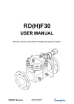
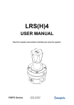
Inertisation /
Tankblanketing regulators
USER MANUAL
TBRSF16
Read the complete manual before installing and using the regulator.
TBRSF 16 User Manual
Rev.date: 20-09-2010
WARNING
INCORRECT OR IMPROPER USE OF THIS PRODUCT CAN CAUSE SERIOUS PERSONAL
INJURY AND PROPERTY DAMAGE.
Due to the variety of operating conditions and applications for this product, the user is solely
responsible for making the final proper decisions concerning the correct assembly and functioning of
the product and assuring that all the performance, safety and warning requirements are met.
• Users must be trained and equipped for the handling, use and servicing of pressure products
and systems.
• Users must contact their gas or liquid supplier for specific safety precautions and instructions.
• Gaseous media should be free of excessive moisture to prevent icing at high flow.
• Always wear the appropriate protective clothing, including safety glasses, gloves etc. if required.
• Follow the applicable safety and maintenance procedures.
• Obey specific local regulations.
• Do not exceed the maximum inlet and outlet pressure of the product or its accessories.
• Operate within the temperature limits and other conditions specified for the product.
• Do not to drop or damage the product in any other way. This may negatively effect the
performance of the product which can cause the product to malfunction.
• Venting fluids and gases can be dangerous. Vent to a safe environment away from people.
Ensure adequate ventilation.
• This product is not oxygen clean and therefore not suitable for oxygen service.
If there are questions or problems regarding the installation, operation and maintenance these should
be directed to the proper authority on site before continuing.
TBRSF 16 User Manual
Rev.date: 20-09-2010
CONTENTS
1
2
3
4
5
Introduction .............................................................................................................................................. 1
1.1
Detailed description ........................................................................................................................... 1
1.2
Special features and options ............................................................................................................. 1
1.3
Typical picture of the TBRSF16 (standard)....................................................................................... 2
1.4
Typical picture of the external feedback ........................................................................................... 2
Installation ................................................................................................................................................ 3
2.1
Points of attention before installation ................................................................................................ 3
2.2
Oxygen service ................................................................................................................................. 3
2.3
Installation instructions ...................................................................................................................... 4
2.4
External feedback ............................................................................................................................. 5
Operation .................................................................................................................................................. 6
3.1
Required tools for operation .............................................................................................................. 6
3.2
Points of attention before operation .................................................................................................. 6
3.3
Changing the setpressure ................................................................................................................. 6
Maintenance ............................................................................................................................................. 7
4.1
Required tools for maintenance ........................................................................................................ 7
4.2
Points of attention before removal from the system ......................................................................... 8
4.3
Removal from the system ................................................................................................................. 8
4.4
Disassembly ...................................................................................................................................... 8
4.5
Inspection of disassembled parts ...................................................................................................... 8
4.6
Points of attention before assembly .................................................................................................. 8
4.7
Assembly ........................................................................................................................................... 8
4.8
Recommended torques ..................................................................................................................... 9
4.9
Testing............................................................................................................................................... 9
Trouble shooting.................................................................................................................................... 11
TBRSF 16 User Manual
Rev.date: 20-09-2010
1
1 Introduction
1.1
Detailed description
This regulator is a diaphragm sensing spring loaded pressure regulator, designed for low outlet pressure
at high gaseous flow. It is ideal for highly accurate control of pressure because of it’s large effective
sensing area. Combined with a lever between the diaphragm and the valve, the regulator is ideal for use
in low pressure tankblanketing.
The regulator comprises a body and spring housing bolted together and has a removable seat and valve.
The product is designed to be used between -20 ºC and +80 ºC, whether ambient temperature or media
temperature.
The TBRSF16 needs outletpressure to close the valve, therefore the regulator is not leak tight with
atmospheric outletpressure. The regulator can stand high inletpressure, because of the balanced valve.
The maximum in- and outlet pressure for the TBRSF16 are:
-
Inlet pressure 0 – 16 bar
Outlet pressure 0 – 700 mbar *
* Make sure the downstream pressure cannot exceed 700 mbar as the max. allowable
working pressure for the diaphragm enclosure is 700 mbar.
Standard features:
-
ss 316L throughout
diaphragm sensing
3 outlet ranges
external feedback *
1.2
Special features and options
-
internal pressure sensing
suction tube
factory set locking ring
* When using the TBRSF16 with external feedback, make sure that the outlet pressure is fed
back to the external feedback connection before applying pressure to the regulator.
Failing to do so may lead to damage and non-functioning of the regulator as the inlet
pressure will be put straight through to the outlet.
TBRSF 16 User Manual
Rev.date: 20-09-2010
2
1.3
1
2
3
4
6
7
9
10
1.4
Typical picture of the TBRSF16 (standard)
body assembly
springhousing assembly
body plug
springhousing cover
lever
valve assembly
seat
valve holder assembly
12
13
14
15
16
17
18
19
hexagon head screw
diaphragm plate
diaphragm
diaphragm screw
o-ring
locknut
o-ring
o-ring
20
21
22
23
24
25
26
27
guide bush
set spring
springguide
setscrew
o-ring
valve spring
socket head cap screw
ring
28
29
30
31
34
35
36
37
hexagon nut
locknut
hexagon head screw
bush
o-ring
blind plug, 1/4” bsp
ring
socket head cap screw
Typical picture of the external feedback
The TBRSF16, with an external feedback, uses the connection 1/4” BSPP connection on the cover to sense the outlet pressure.
The suction tube is blocked, with a bolt and ring, mounted in the valve holder assembly (nr. 10). See the sketches above.
TBRSF 16 User Manual
Rev.date: 20-09-2010
3
2 Installation
WARNING
A PRESSURE REGULATOR IS NOT A SHUT-OFF VALVE AND SHOULD NOT BE USED AS SUCH
2.1
Points of attention before installation
This regulator can be equipped with different options and connections.
Before installing the regulator you should fully understand the options and the suitability of your particular
regulator and its suitability for the application.
sketch with mounting modes
-
The preferred mounting position of the regulator is vertical with the springhousing facing
horizontal. (see above sketch). The reason is the weight of the diaphragm plate, in this position it
does not effect the regulation.
It may be necessary to remove the regulator from the system during maintenance or service.
Make sure that this is possible.
The regulator is suitable for gases. Check if the materials on the assembly drawing, which came
with the regulator, are compatible with the used media.
The product is designed to be used between -20 ºC and +80 ºC, whether ambient temperature or
media temperature. In all other cases consult SWAGELOK B.V..
The regulator is standard not oxygen clean and is not suitable for oxygen use.
2.2
Oxygen service
-
-
-
Specification of materials in regulators for oxygen service is the user’s responsibility. SWAGELOK
B.V. can perform cleaning for Oxygen service based on ASTM-G93LevelC/CGA4.1 at additional
cost.
TBRSF 16 User Manual
Rev.date: 20-09-2010
4
2.3
Installation instructions
-
Verify that the regulator, the connections and its accessories are undamaged.
Verify that the regulator and its accessories are suitable for the system operating pressure and
have the proper connections.
Carefully clean all pipes and connections. Any swarf, lint, wire etc. may cause seat leakage.
Verify the flow direction of the system and mount the TBRSF16 accordingly.
Securely make the appropriate connections to the regulator in accordance with the procedures
recommended by the manufacturer of the connections.
Make sure the downstream pressure cannot exceed 700 mbar.
Shut-off valves should be mounted in the system for service or maintenance.
If earthing is required, connect an earth wire under a springhousing bolt.
-
TBRSF 16 User Manual
Rev.date: 20-09-2010
5
2.4
External feedback
The purpose of the external feedback on a TBRSF16 is to get a more accurate regulation of the down
stream pressure. This can be achieved by sensing the outlet pressure downstream of the regulator and
feeding it back to the regulator. For this purpose SWAGELOK B.V. has provided a special connection,
marked on the regulator itself as "P2 feedback".
Note: The feedback MUST be used; failure to do so could cause serious problems.
The external feedback must be installed as follows.
-
In a pipe-line application, the sensing line is to be connected in a turbulence-free zone in the
downstream piping, at a distance of approximately 5x the outside diameter of the down stream
piping.
The sensing tube must be connected on top of the downstream piping.
The size of the sensing line should be ⅜” or ½” tubing.
Note: Never connect the sensing line downstream of a shut-off valve.
Pipe-line application
mounted correctly
mounted incorrectly
Tankblanketing application
mounted correctly
mounted incorrectly
TBRSF 16 User Manual
Rev.date: 20-09-2010
6
3 Operation
3.1
Required tools for operation
Use a socket wrench (19 mm) with an extended piece to change the setpressure.
3.2
Points of attention before operation
-
The regulator can be hot or cold, depending on the environmental temperature and the used
media temperature. Take the necessary precautions before operating or touching the product.
The regulator is a non-venting type; a shut-off valve on the outlet side must be opened to relief the
pressure on the outlet side.
When the pressure has been set in a no-flow situation, the pressure will drop when gas starts to
flow. This phenomenon is usually referred to as the “lock-up” and does not indicate a problem
with the regulator.
A decrease in the flow will result in a rise of the outlet pressure. An increase in the flow will result
in a fall of the outlet pressure and is usually referred to as the “droop”.
This phenomenon does not indicate a problem with the regulator.
A decrease of the inlet pressure will result in a rise of the outlet pressure.
An increase of the inlet pressure will result in a fall of the outlet pressure.
This phenomenon is usually referred to as the “dependency” and does not indicate a problem with
the regulator.
-
-
-
3.3
Changing the setpressure
-
Check the supply of medium at the inlet side.
Make sure the inlet pressure is higher than the required outlet pressure and that the inlet pressure
does not exceed the maximum allowable inlet pressure. Open the shut-off valve at the inlet side.
Slightly open a shut-off valve, in the system at the outlet side, to allow a minimal flow.
Turn the setscrew clockwise to increase the setpressure.
Turn the setscrew counterclockwise to decrease the set pressure.
-
TBRSF 16 User Manual
Rev.date: 20-09-2010
7
4 Maintenance
WARNING
INCORRECT OR IMPROPER REPAIR OR SERVICING OF THIS PRODUCT CAN CAUSE SERIOUS
PERSONAL INJURY AND PROPERTY DAMAGE.
SWAGELOK B.V. recommends the product to be removed from the system and to be shipped to
SWAGELOK B.V. for service or maintenance as all regulators must pass rigid acceptance tests before
leaving the factory.
All repairs and servicing of this product must be performed by factory certified personnel and tested for
operation and leakage.
If this procedure is not followed for any reason, or if any customer changes are made to the product,
SWAGELOK B.V. cannot assume responsibility for the performance or safety of a customer repaired
product or for any damage resulting from failure of the product.
The product should be checked periodically for proper and safe operation.
It is the users sole responsibility to determine the frequency of maintenance based on the application.
L RECOMMENDATION
SWAGELOK B.V. RECOMMENDS TO HAVE SPARE-PART KITS READILY AVAILABLE ON SITE.
All regulators require maintenance at scheduled intervals. Annual maintenance is recommended under
normal use.
From experience SWAGELOK B.V. can tell that especially during the start-up of a system, the demand
for spare-part kits is there.
Despite all the effort taken to assure a clean system, there is usually some debris left in the system,
which can damage the regulator.
Having spare-part kits on site will save time and money, as the downtime of the system will be reduced
to a minimum, whether during start-up or normal operation.
4.1
Required tools for maintenance
-
a vice to fasten the regulator
pincers to take out the o-rings
a torque wrench
a torque wrench hexagon head key 5
socket wrenches 8 / 17 / 19
a wrench 44
a “seat retainer” removing tool
media and temperature compatible lubricant for reassembling threaded parts
media and temperature compatible lubricant for o-rings
soapy water for leak-testing
TBRSF 16 User Manual
Rev.date: 20-09-2010
8
4.2
-
-
4.3
4.4
-
Points of attention before removal from the system
SWAGELOK B.V. recommends removing the regulator from the installation.
Make sure that a spare-part kit is present.
Check if the used media is hazardous or toxic.
If required take the necessary safety precautions to ensure a safe workspace and your personal
safety.
Vent to a safe environment away from people and ensure adequate ventilation.
Follow your system safety, maintenance or special local procedures when removing the regulator.
The product can be hot or cold, depending on the environmental temperature and the used media
temperature. Take the necessary precautions before operating or touching the product.
Removal from the system
Isolate the regulator from all pressure sources by closing the appropriate valves.
Turn the setscrew counterclockwise to decrease the setpressure; a shut-off valve on the
downstream side must be opened to relief the pressure.
Make sure, the inlet and outlet pressure are both reduced to zero and the setscrew is turned
counterclockwise until there is no more spring force on the setscrew.
Disassembly
Loosen the socket head screws (16 pcs.M6) and remove the springhousing and the set spring.
Loosen the nut on the diaphragmscrew and remove the diaphragmplate and the diaphragm.
Loosen the hexagon head screws (4 pcs.M10) and pull out the valve holder assembly, together
with both levers and the valve assembly.
Loosen the hexagon head screws (3 pcs.M05) to remove the valveassembly and both levers from
the valve holder assembly.
Loosen the bodyplug from the body and remove the seat by turning it counterclockwise.
4.5
Inspection of disassembled parts
-
Check all parts for abnormal wear. Replace all parts in case of doubt.
4.6
Points of attention before assembly
-
4.7
All parts must be clean and undamaged before starting assembly.
SWAGELOK B.V. recommends replacing all o-rings and the diaphragm before assembly.
All threaded parts must be lubricated a little before assembly, this to avoid galling of threads.
All o-rings need to be lubricated a little to improve the lifetime of the o-ring and the performance of
the regulator.
Assembly
Follow the points for disassembly in reverse order to assemble the regulator.
TBRSF 16 User Manual
Rev.date: 20-09-2010
9
4.8
Recommended torques
-
Seat
Bodyplug
Hexagon head screws (3 pcs M05)
Hexagon head screws (4 pcs M10)
Nut on the diaphragmscrew (M10)
Socket head cap screws (16 pcs M06)
4.9
Testing
10 Nm
30 Nm
10 Nm
40 Nm
10 Nm
10 Nm
Check the TBRSF16 for leakage across the seat, bodyplug and the diaphragm.
Check the required outletpressure range and function.
-
Maintain a test pressure on the upstream side of the regulator.
Turn the setscrew clockwise, till there is 50% of the outletpressure range.
Stop turning the setscrew. The outletpressure may not rise more then the closing pressure.
Turn the setscrew clockwise, and stop when the maximum outletpressure is reached.
Check for leakage across the diaphragm and check the small hole in the springhousing for bubbles
by using a little soapy water.
Check for leakage across the bodyplug.
If there is leakage across the seat or the diaphragm, the damaged parts must be replaced.
TBRSF 16 User Manual
Rev.date: 20-09-2010
10
TBRSF 16 User Manual
Rev.date: 20-09-2010
11
5 Trouble shooting
Problem:
The outlet pressure creeps up, without turning the adjustment knob.
Cause:
A damaged valve and/or seat.
Solution:
Replace the valve assembly
Problem:
Controlled pressure drops off sharply even when the flow is within regulator capabilities.
Cause:
Not enough inlet pressure.
Solution:
Make sure there is enough.
Problem:
Constant leak through the hole at the side of the springhousing.
Cause:
Damaged diaphragm, or not enough torque on the nut on the diaphragmscrew.
Solution:
Replace the diaphragm, or tighten the nut.
Problem:
The required outlet pressure can not be reached.
Cause:
The inlet pressure is not high enough.
Solution:
Make sure that the inlet pressure is sufficient.
Problem:
The outlet pressure rises too much when going from a dynamic to a static situation.
Cause:
There is too much flow in the dynamic situation.
Solution:
Check the specific application data with the flow curves in our documentation.
Problem:
The outlet pressure does not drop when the setscrew is turned counterclockwise.
Cause:
The regulator is standard non-venting.
Solution:
A shut-off valve in the outlet line must be opened to reduce the outlet pressure.
Warranty Information
Swagelok products are backed by The Swagelok Limited Lifetime Warranty.
For a copy, visit swagelok.com or contact your authorized Swagelok representative.
TBRSF 16 User Manual
Rev.date: 20-09-2010