1
Reincarnate Historic Systems On FPGA with Novel Design Methodology
Naohiko Shimizu
IP ARCH, Inc. Tokai University
http://www.ip-arch.jp
the system must be consist of hardware and software. Then
students will learn the relationship or co-operation of them.
But case studies on real systems are a little difficult, because
many state of art systems will not describe their detailed
engineering implementation design and methods in publications.
In this paper, I will introduce some of our past projects
and design methodology to make up for that with historic
systems.
Abstract— In this paper, I introduce my and my students
projects to reincarnate historic systems on FPGA. Our projects
are not replica nor paper-model of historic systems, but
reorganized and working system on FPGA with novel and
progressive design methodology. I mean progressive as under
the development, because I have developed them and I am still
improving the methodology and tools very often to use them
by myself.
In this paper, I also introduce my design methodology and
tools which is used in my and my students projects.
I. I NTRODUCTION
II. O UR PAST PROJECTS OVERVIEW
I love computer. I love CPU. After 10 years experience on
mainframe and super computers design at Hitachi, I quited
Hitachi and move to Tokai University in 1995. I have two
reasons, one is that Hitachi decided to stop development of
mainframe CPU, another is that I believe the future of FPGA
for MY systems.
When I became a teacher, I hoped students to learn
computer system from the history. In Japanese language,
the origin of the word ’Manabu’ which means ’study’ is
’Maneru’ which means ’copy.’ Artists start their life with
copy of good styles and techniques. Many technicians in
traditional art also start their life with copy of the master’s
style.
On the other hand, with engineering curriculum, we
will start to study fundamental theories in comprehensive
subjects. We use projects and laboratory experience to
compensate for the gap between fundamental theories and
engineering style[1]. But project sometimes is too small to
get knowledge from them. And the laboratory experience
sometimes is too difficult for undergraduate students to learn
the engineering style or design from it.
The target systems for the projects were listed as:
2000 CP/M80 system with solid state storage[2].
2001 PCI bus controller[3].
2002 PDP11/40m compatible system with UNIX running
on it[4][5].
2002 Space Invaders[6].
2003 FreeDOS system[7].
2004 Vax11 compatible CPU without MMU[8].
2005 Hard wired painting tool[9].
2007 UML based 6502 CPU development[10].
2009 UML based MIPS subset CPU development[11].
I assigned two student for Space Invaders, three for painting
tool and four for UML based 6502. But most of the projects
are carried out with only one undergraduate student.
We mainly use free tools because most students need extra
work at their home in mid night. And they need to run tools
on their own PC. Free EDA tools for the projects are:
1995 Alliance VHDL[12]
1996- PARTHENON[13]
2002- sfl2vl[14], Icarus Verilog[15]
2009- above plus uml2sfl
From 1996, I changed the hardware description language
to SFL with PARTHENON EDA system. Because many
students had difficulty with VHDL, and the combination of
PARTHENON and SFL makes their life easy. But the license
of PARTHENON is restricted to educational use only. If
graduated students want to use SFL, there was no option.
Then I wrote a new synthesizer ’sfl2vl’ in 2002, and started
up IP ARCH, Inc. to provide SFL for industry. The sfl2vl
converts SFL file to VerilogHDL. At these days, I think
it is important for students to have some experience on
VerilogHDL. With this tool, they will write a simulation
script with VerilogHDL, and logic with SFL. The uml2sfl
was also developed by me in 2009. Since then, I extensively
have upgraded the tools and methodology.
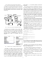
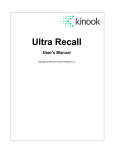
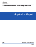
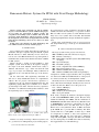
Fig. 1.
PDP11/40m compatible system on an FPGA (Altera Cyclone
EP1C3) and the console output when running the UNIX v6
I believe case study on existing or historical system is one
of a good choice for undergraduate project. In this purpose,
978-1-4244-5028-2/09/$25.00 ©2009 IEEE
10
III. C URRENT DESIGN FLOW OF THE PROJECTS
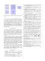
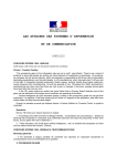
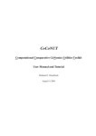
private shown as ’-’, we assume that attribute is placed inside
the module.
Also we map the operations to functionality of the module. In SFL and NSL, we have special syntax to describe
stage invocation functions and combinational functions. If
visibility of an operation is public, shown as ’+’, we assume
the operation will be invoked from other modules. In other
words, the operation is incoming function to this module.
Or if visibility of an operation is private, shown as ’-’, we
assume the operation will be invoked within the module.
The main usage of within module operation is pipeline stage
or FSM state invocation. Or if visibility of an operation
is protected, shown as ’#’, we assume the operation will
activate outer module function. In other words, the operation
is outgoing function from this module.
In UML, black arrows means the composition relations.
In this figure, two modules are imported to the main module
as sub-modules. There is no example in the figure, but we
can use white arrow as inheritance relations. In that case, all
attributes and operations of parent class will be imported to
the child class.
The uml2sfl will generate input/output terminals, registers, sub-module instances and stages with their arguments(pipeline registers). Therefore, it generates most of the
static elements automatically, and students can concentrate
on the behavior of each stages.
The Figure 4 is the operation part of the generated skeleton
NSL code which is extracted from UML class diagram.
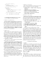
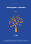
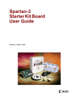
Fig.2 shows the current design flow of the projects which
uses UML for specification and SystemC for verification.
We are just in the first annual year since we start to use
new method. Then we have still only a few reports with
this method. But these reports shows good response on this
methodology.
Architecture
level
modeling
UML
SystemC
SystemC
UML2SFL
Semi auto generate
+ manual entry
manual entry
prototype
NSL
Verification
codes
sfl2vl
Verification
Auto generate
SystemC
RTL
Verilog
Verification
FPGA
Fig. 2.
Current projects design flow with UML and SystemC
The uml2sfl will convert UML class dialog to NSL or SFL.
Where NSL is stand for the Next generation Synthesizable
Language which is ancestor of SFL. SFL is the hardware
description language for PARTHENON[13]. And the sfl2vl
will convert them to RTL level VerilogHDL or RTL level
SystemC.
/* instrin start() operation */
instruct start {
}
/* proc ifetch(PC) operation */
proc ifetch {
}
/* proc decode(InstReg) operation */
proc decode {
}
/* proc exec(oprA,oprB) operation */
proc exec {
}
/* proc memory(DataRes) operation */
proc memory {
}
Fig. 4. The Operation Part of Generated NSL Skeleton Code Extracted
From UML Class Diagram for Multi-Cycle MIPS subset CPU. The protected
operations are not listed here, because they will be invoked from this module
and there are no operations within this module.
Fig. 3.
The Figure 5 shows the modified code by the student for
the ifetch and decode procedures. To save space, we only
show a part of the CPU code.
UML Class Diagram for Multi-Cycle MIPS subset CPU
IV. P REPARATION FOR UNDERGRADUATE PROJECTS
Before we start undergraduate projects, we need a ton
of preparations. Because the design methodology of many
historical systems are obsolete, we must select or make
alternative methodology. To select or make methodologies, I
must consider a few problems.
1) Materials must be available legally for use in class
room.
2) Tools should be freely available for students homework.
From 2009, we use UML class dialog for the initial design
of our project. Fig.3 is the dialog which I provided to students
for their initial design. UML class dialog is consist of class
name, attributes and operations. We map the class name to
module name of hardware. We map the attributes to instances
within the module such as registers, wires or input/output
terminals. If visibility of a UML attribute is public, shown
as ’+’, we assume that attribute will be a terminal which
connect to outer modules. Or if visibility of the attribute is
11
/* proc ifetch(PC) operation */
proc ifetch {
decode(memRd(PC).DataIn);
PC:=alu.exec(ADD,PC,0x00000004).Result;
}
/* proc decode(InstReg) operation */
proc decode {
sel tmpoprB<32>;
any {
typeR| beq | bne:
tmpoprB = gr.regrdB(InstReg<20:16>).RegOutB;
lw | sw | addi | andi | ori :
tmpoprB = 32#InstReg<15:0>;
}
exec(gr.regrdA(InstReg<25:21>).RegOutA, tmpoprB);
}
Fig. 5.
C. Hardware documentations
I have collected some hardware documentations by myself.
I use these documents for our projects. It includes:
• MCS6500 Micro Computer Family Programming
Manual[22]
• MCS-80/85 Family User’s Manual[23]
• pdp11 processor handbook pdp11/20,15,r20[24]
• pdp11 processor handbook pdp11/45[25]
• pdp11 peripherals and interfacing handbook[26]
• MCS-86 USER’S MANUAL[27]
Student Modification to the Extracted NSL
D. Hardware design examples
Students need to learn hardware description language. But
it is not enough to design elegant system. In addition to learn
the language, students must deeply read good design examples. For this purpose, I prepared some example circuits.
1) SP/1: 8bit 5 stage pipeline RISC (1998)
2) SN/X: 16bit non-pipeline RISC with compiler and
assembler (2001)
3) my80: MCS-80 compatible CPU (2001)
4) m65: MCS6502 compatible CPU (2002)
5) mz80: Z80 compatible CPU (2002)
6) my88: i8088 semi-compatible but incomplete CPU
(2002)
7) Stopwatch system with bitmap display on VGA
For all examples, I carefully design the data path to keep
the number of gates as low as possible. Fortunately, many
hardware manual in 70’s show the block diagram of CPU.
I checked the instruction set and data path repeatedly to
minimize my design. Especially, for m65, I like 6502 and
I know the instructions well, and I enjoyed to design it. The
m65 CPU consist of two files one is CPU body, the other
is ALU. The total number of the lines is about 1000 lines.
It is not so difficult to read 1000 lines CPU. Therefore, I
recommended students who are interesting in CPU design to
read m65 deeply. The other students who were not interested
in CPU design, used these example as is for their projects.
Sometimes it had bugs and they repaired.
3) Complexity must be managed as low as possible.
4) Use of Hardware Description Languages.
A. Hardware Design Environment
The main hardware design language for the projects is
NSL or SFL. We use VerilogHDL and/or SystemC for verification. And the target hardware is FPGA. The target device
has been varied from time to time, depend on the availability
and cost. The selection of the hardware description language
is very important for the success of the projects. For short
cutting the students installation, I compiled a set of these
tools in an archive LiveCygwin.zip. Students can download
it and extract it on some directory.
B. REAL software
Back to 1970’s, many computer engineers who are still active in this industry, read ’Lions’ commentary on UNIX[16].’
We were very excited with the detailed design of UNIX (the
SOURCE) that is shown in Lions’ book. His book was not
publicly available until 1996. In addition to his book, Caldera
put the license of ancient UNIX as open source in 2002[17].
Also, in 2003, Steve Wozniak said that Apple-I’s schematics and ROM are public[18].
”The best anyone could say was that it was mine and that
I made it public,” Woz said to Briel.
Another major player in micro processor industry was Intel
or Zilog with CP/M for 8bit, and Intel with MS-DOS for
16bit CPU. In 2001, CP/M unofficial site’s Gaby Chaudry
negotiated with Lineo that was the license holder of CP/M,
for publicly distribution of CP/M and related technology[19].
MS-DOS may not be open, but open source project FreeDOS
became version 1.0 in 2006[20].
We also have Linux[21] and BSDs for advanced operating
systems. I did use Linux for operating system projects, but
I have not tried them for hardware projects, yet.
For students who love TV games, I contracted with Taito
Corp. to use the Space Invader game software for laboratory
education. Unfortunately, the program was binary form.
It is very important for us to get source code of our target
projects. Because during the development of hardware we
will have a lot of problems which are difficult to solve
without source.
V. U NDERGRADUATE PROJECTS
A. CP/M80
In this project, we decided to use solid state storage. We
extended the address line of i8080A instruction compatible
CPU up to 24 bits that is 16MB of address space. And
we added new instructions to access extended address space
which use three 8bit registers to designate 24bit address. We
also developed a special BIOS for this new storage system.
We used Altera EPF10K30AQC240-3 for the implementation. It uses 1260 logic cells and the maximum clock
frequency is 8.9MHz.
B. Space Invaders
This project also uses my80 as a CPU. But it incorporate
many I/O functions and interrupt timer. Original Taito’s
Space Invaders had analog sound circuit based on OP amp
12
10k
0.47u
VCC
Chrom1
C1
C6
R1
10k
0.47u
470u
GND
2.7k
R5
Chrom2
C2
Digital in
2SC1815
100u
10k
0.1u
C3
C5
R3
R6
3.6k
20k
330p
C4
R7
3300pF
75
R4
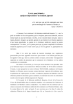
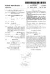
Fig. 9.
Fig. 6.
The Analog part of Space Invader Project
Reset
The picture of CP/M running on Altera EPF10K30A
ROM_access
Master_Clock
14.318MHz
Clock_1.7MHz
Write_enable
ROM_access
Controller
Addressdecoder
Read_enable
Write_enable
Address
Address
Expansion
Address Bus
Audio out
VIDEO OUT
Csync
Burst
Signal
0.1uF
4.7K
4.7K
R2
Master_Clock
Memory
RAM ROM
Data
My80_Clock
Write_Data
sound_mix
Read_Data
Address Bus
4BIT
CHROM_1
VGA Controlor
clock 1.7MHz
Analog
Circuit
CHROM_2
C_BURST
SOUND
CSYNC
4BIT
13.98KHz
clock
Divider
white noize
generator
4BIT
FIR Band
Pass Filter
decay
enable
JOYPAD
JOYPAD DATA
to TV
FPGA EPF 10K 30AQC240-3
23 22
16 15
RAM/ROM SELECT
Fig. 10.
0
(a) Nomal Access Mode
B
Disk#
H
Track#
select data
The Block Diagram of Space Invader Project
method within CPU. We started to design CPU without
MMU at first. While he developing CPU, I made a series
of lectures on Lions Commentary on UNIX for him. There
was an incomplete porting of GNU C compiler for PDP11,
and we fixed the compiler to use in debugging our CPU. We
also ported ’proc[28]’ real time operating system to our CPU
for demonstration of embedded system applications.
L
Sector#
sound
generator
SOUND
Address
4BIT
NTSC
0b0000000
OUT
CSYNC
SOUND 1bit
White
Noise
Byte Adrs
POP11 CPU core
23
17 16
13 12
7 6
0
Register
File
ALU
RS-232C
controler
(memory mapped)
(b) RAM Disk Access Mode
ALU BUS
START
SOURCE BUS
DESTINATION BUS
Fig. 7.
ADDRESS BUS
Address Assignment
What mode?
OP-CODE BUS
Interrupt/Acknowledge
Instruction
Decode
Unit
Addressing
Mode
Unit
Instruction
Unit
Register
Autoincrement
Vector
Decrement Reg
Memory load
Increment Reg
Register load
DATA
DATA
ADDRESS
ADDRESS
On-chip
Memory
On-chip
Memory
Timer
interrupts
Index
On-chip
Peripheral
Memory load
PC+2
Index calculate
HIGH PRIORITY
and SN76477 sound chip. But we decided to make everything in digital with triangle wave generator, random noise
generator and FIR filters. Also original Space Invaders had
monochrome display and color tape attached on the screen.
But we generate NTSC color signal with minimum analog
circuit.
Cascaded Connect
Interrupt
Controler
Memory control
Unit
Autodecrement
Priority
Deferred mode?
No
Yes
Memory load
On-chip
Peripheral
END
Fig. 11. The block diagram and addressing mode state chart of pdp11
compatible CPU
As next step, we implemented MMU for our processor.
And instead of old RK disk drive, we want to use IDE
hard drive in our system. Then we made protocol converter
from/to RK disk drive to/from IDE hard drive.
When implemented on an FPGA, pdp11 without MMU
will use 1678 logic cells and it run up to 9MHz on Altera’s
EPF10K30E-3, and pdp11 with MMU will use 2687 logic
cells and it run up to 20MHz on Altera’s EP1K00-1.
Fig. 8. Space Invaders compatible hardware running on Altera EPF10K30E
and the NTSC signal from it
D. FreeDOS
In this project, we tried to make i8086 instruction compatible CPU. It has many complex features such as prefix
instruction, string instruction, segmentation, etc. We separated bus interface unit and execution unit of the CPU and
implemented a instruction fetch queue as described in the
MCS-86 manual.
When we fitted into an FPGA (Altera’s EPF10K30E-3),
we used 1503 logic elements. It will work up to 20MHz.
C. PDP11
The student for this project deeply read the m65 example.
And he understand about addressing mode and it decoding
13
of logic cells are 3884 and frequency is 9.16MHz.
POP-11/40 Processor
E. Hardware Paint Tool
Interrupt
controller
POP-11/40
Processor Core
Memory
management
unit
RK-IDE
protcol
converter
(DMA unit)
RS-232C
controller
Embedded
Array
Blocks
This project did not use any CPU. All the controls are
hard wired. The module will get input from PS/2 mouse and
put picture on VGA display. The cursor is implemented as
a sprite image.
Timer
ps2c
ps2d
1
1
bidirect module
top module
IDE
controller
ps2 module
out_status out_xdir
8
8
out_ydir
8
vgactl module
memcount module
syncout module
mempaint1
module
Memory
Terminal
Fig. 12.
HDD
The block diagram of pdp11 compatible CPU with MMU
1
HS
BHE write read memio DATA BUS
SEGMENT
FILE
QUEUE
FETCH
INT INTA
BUS UNIT
CONTROLLER
OP CODE
MEMORY/IO
ACCESS
BRANCH
INTERNAL
DATA BUS
EA BUS
1
vgaB
We have two demonstrative project for SFL/NSL users.
One is Apple-I software compatible system on an FPGA. We
call it as AISoC. It includes 6502 compatible CPU, Apple-I
software compatible keyboard and display interface which
is converted to serial port, PS/2 keyboard interface, VGA
character display interface, 7 segment LED interface, LCD
panel interface, respectively. When complied for Spartan3
IP REG
INSTRUCTION
QUE
1
vgaG
VI. E XAMPLE P ROJECT FOR SFL/NSL USERS
BUS UNIT
ADDRESS
GENERATER
1
vgaR
Fig. 15. Hardware Painting tool with Mouse running on Xilinx Spartan3
starter kit
When the CPU was ready to simulation, we ran the
drystone benchmark on simulation. We also wrote BIOS
routines which is compatible with PC. We implemented 6
bios entries: int 10, int 11, int 12, int 13, int 16, int 1a. At
that time, FreeDOS requires 4 of i80186 instructions. Then
we added these instruction to our processor.
ADRS BUS
1
VS
CONTROL
SINGNALS
EXECUTION UNIT
DATA PATH
REGISTER
FILE
ALU
MULTIPLYER
DIVIDER
reset
TEMPORALY
REGISTER
EA
REGISTER
INSTRUCTION
FETCH
INSTRUCTION
FETCH
OPERAND
FETCH
WRITE
BACK
EXECUTION
OPERAND
FETCH
INTERRUPT
INTERRUPT
STRING
INSTRUCTION
INSTRUCTION
DECODER
EXECUTION
UTNIT
CONTROLLER
STRING
EXECUTION
WRITE
BACK
BRANCH
Fig. 13. The block diagram and state chart of i8086 compatible CPU
running on Altera EP1K100
Fig. 16.
Class Diagram of AISoC for Xilinx Spartan3/3E starter kit
EA BUS
DATA OUT BUS
DATA IN BUS
in1
xc3s200ft256-5, ISE reports that it will use 1208 LUTs and
maximum clock frequency is 76.145MHz. That means 70
times faster than original Apple-I. To be honest, we divided
master clock by 2, then real CPU clock will be half of the
report. Of course, it is still very fast compare to the original
Apple-I.
Another example is Midway game platform which was
used in Space Invaders. The students projects used NTSC
video system for the display output. I changed the video
system to VGA that is more usable for PC users.
ALU
in2
in1
in2
out1
Multiplyer
&
Divider
out2
REG FILE
AH
AL
BH
BL
CH
CL
DH
DL
SP
BP
SI
DI
SRC REG
OPC REG
INSTRUCTION
DECODER
OP CODE
DST REG
TMP REG
FLAG REG
CONDITION
for BRANCH
EA REG
INTERRUPT
VECTOR
ADDRESS
Fig. 14.
The data path and timing chart of i8086 compatible CPU
When implemented in Altera FPGA EP1S10, the number
14
[4] Y. Iida and N. Shimizu, “Design of a pdp11 compatible cpu with
programmable chip,” 10th FPGA/PLD Design Conference, User presentation, pp. 93–100, 2002.
[5] ——, “Design of pop-11(pdp-11 on programmable chip),” Proceedings of Asia and South Pacific Design Automation Conference 2004,
pp. 571–572, 2004.
[6] Y. Iida, K. Yamaguchi, and N. Shimizu, “Invaders soc,” The 22th
PARTHENON user meeting, pp. 72–80, 2003.
[7] M. Oyama and N. Shimizu, “Development of i8086 instruction
comaptible processor core and lsi development environment with sfl,”
11th FPGA/PLD Design Conference, User presentation, pp. 35–41,
2003.
[8] N. Kondo and N. Shimizu, “Invaders soc,” The 25th PARTHENON
user meeting, pp. 57–66, 2004.
[9] S. Kinoshita, S. Namiki, M. Horiguchi, and N. Shimizu, “Development
of paint tool hardware by learner and education effect,” The 26th
PARTHENON user meeting, pp. 11–17, 2005.
[10] H. Ohtsuki, S. Namiki, N. Shiozawa, K. Matsunaga, and N. Shimizu,
“Applying mdd with uml for cpu development,” The 31th
PARTHENON user meeting, pp. 11–16, 2007.
[11] N. Shimizu, M. Ikura, W. Wiriya, and S. Chivapreecha, “A new logic
circuit design methodology with uml,” The 24th International Technical Conference on Circuits/Systems, Computers and Communications,
2009.
[12] LIP6. (1990) Alliance vhdl. [Online]. Available: http://wwwasim.lip6.fr/recherche/alliance/
[13] Y. Nakamura, K. Oguri, H. Nakanishi, and R. Nomura, “An rtl
behavioral description based logic design cad system with synthesis
capability,” IFIP Computer Hardware Description Language and their
Applications, pp. 64–78, 1985.
[14] N. Shimizu, “The design of sfl2vl: Sfl to verilog convertor based on
a lr-parser,” Proceedings of the Workshop on Synthesis And System
Integration of Mixed Information Technologies, pp. 251–257, 2003.
[15] M. Baxter. (2001) Open source in electronic design automation.
[Online]. Available: http://www.linuxjournal.com/article/4428
[16] J. Lions, Lions’ Commentary on UNIX. Charlottesville, VA, USA:
Peer-to-Peer Communications Inc., 1996.
[17] I.
F.
Darwin.
(2002)
Why
caldera
released
unix:
A
brief
history.
[Online].
Available:
http://linuxdevcenter.com/pub/a/linux/2002/02/28/caldera.html
[18] L. Kahney. (2003) Woz ok’s apple i resurrection. [Online]. Available:
http://www.wired.com/gadgets/mac/news/2003/09/60329
[19] T. Gasperson. (2001) Cp/m collection is back online with an open source licence. [Online]. Available:
http://www.theregister.co.uk/2001/11/26/cp m collection is back/
[20] FreeDOS.
The
freedos
project.
[Online].
Available:
http://www.freedos.org
[21] M. McLagan. (1991) Linux online. [Online]. Available:
http:/www.linux.org/
[22] MCS 6500 Microcomputer Family Programming Manual, MOS Technology Inc., Norristown, PA, USA, 1976.
[23] The MCS-80/85 Family Uuser’s Manual, Intel, Santa Clara, CA, USA,
1986.
[24] pdp11/20,15,r20 processor handbook, digital equipment corporation,
Maynard, MA, USA, 1972.
[25] pdp11/45 processor handbook, digital equipment corporation, Maynard, MA, USA, 1972.
[26] pdp11/peripherals and interfacing handbook, digital equipment corporation, Maynard, MA, USA, 1972.
[27] MCS-86 USER’S MANUAL, Intel, Santa Clara, CA, USA, 1979.
[28] proc real-time kernel. Nilsen Elektronikk as. [Online]. Available:
http://www.nilsenelektronikk.no/
Fig. 17. Class Diagram of Midway Game Platform for Xilinx Spartan3/3E
starter kit
When compiled for Spartan3 xc3s200ft256-5, ISE reports
that it will use 1352 LUTs and maximum clock frequency
is 241.074MHz. We divided the clock by 5 then effective
CPU clock is about 48MHz. Original Midway game platform
CPU was i8080A and it was worked about 2MHz. In our
example, the CPU run at one bus cycle as one CPU cycle
where original i8080A takes 3 to 4 clocks. Therefore, we
can assume that effective performance will be 70 to 90 times
faster than original.
VII. C ONCLUSION
In this paper, I introduce my and my students project
which reincarnate historic systems on FPGA. For these
projects, students are required vast of knowledge such as
compiler, operating system, bios, assembler, IO subsystems
and of course CPU. The students who tried these projects
were well educated. And many of them are in semiconductor
industry.
And I introduced new methodology which utilize UML
for hardware design. Instead of providing prototype CPU,
I provide only UML class diagram for students. And they
will make up for the behavior description of the CPU.
During last semester, one student who had no experience on
hardware description language tried the MIPS subset projects
with UML. She began from learning hardware description
language, but she took only three weeks to complete the
project and ran a small program on simulation.
My example projects shows that with today’s FPGA
technology, historic systems will run many times faster than
it was. With these advanced performance, I think, we are
able to use historic system on FPGA not only for education
but for embedded systems or other works.
R EFERENCES
[1] ACM-IEEE.
(2004)
Acm
report
in
the
computing
curricula:
Computer
engineering
2004.
[Online].
Available: http://www.acm.org/education/education/curric vols/CE-FinalReport.pdf
[2] C. Kon and N. Shimizu, “Development of 8bit cp/m machine with
linux,” Linux Conference Japan, 2001.
[3] H. Hayasaka, H. Haramiishi, and N. Shimizu, “Design of a pci bus
interface on fpga,” The 20th PARTHENON user meeting, 2001.
15