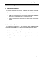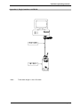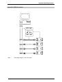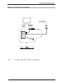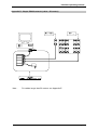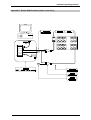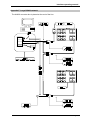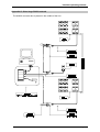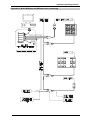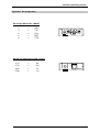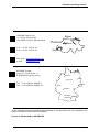
1
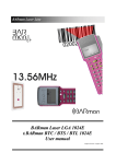
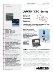
BARman volume 2 Interface operating manual English Version / December 2000 Interface operating manual Page 2 Interface operating manual 1. General description ...................................................................... 6 1.1 1.2 1.3 1.4 1.5 1.6 1.7 BARman system ........................................................................................ 6 Operating manual ......................................................................................... 6 BARman ....................................................................................................... 7 BARman Laser ............................................................................................. 8 t.BARman TAG/TBC..................................................................................... 9 t.BARman BTS ........................................................................................... 10 Interface units for BARman and t.BARman TAG/TBC................................ 11 1.7.1 1.7.2 1.7.3 1.7.4 1.7.5 1.8 Interface unit for BARman Laser and t.BARman BTS .............................. 15 1.8.1 1.8.2 1.8.3 1.8.4 1.9 1.10 1.11 1.12 Interface unit for RS 232 ( ref: BEI232 ) ......................................................... 11 Interface unit for RS 422 ( ref: BIU422 ) ......................................................... 12 Loading unit for 220 V ( ref: BLU100 ) ............................................................ 13 Loading unit for 12 VDC ( ref: BLU012 ) ......................................................... 13 Concentrator interface unit ( ref: CIUxxx )....................................................... 14 Interface unit for RS 232 ( ref: ILS232 ) .......................................................... 16 Interface unit for RS 422 ( ref: ILS 422 ) ......................................................... 16 Loading unit for 220V ( ref: ILS100 )............................................................... 17 Loading unit for 12 VDC ( ref: ILS012 )........................................................... 17 Concentrator interface unit ( ref: ILMxxx ).................................................. 18 Converter box RS232 - RS422 (ref: AX422) .............................................. 19 Connection.................................................................................................. 19 Communication software ............................................................................ 19 2. Hardware installation on a PC.................................................... 20 2.1 2.2 2.3 2.4 Necessary equipment for PC ...................................................................... 20 RS232 single interface unit. ........................................................................ 21 RS422 single interface unit. ........................................................................ 22 Multiple interface unit (concentrator)........................................................... 23 2.4.1 2.4.2 2.4.3 2.4.4 Wall-mounting installation procedure :............................................................. 23 Electrical installation procedure : ..................................................................... 23 Concentrator number setting procedure: ......................................................... 23 AX422 converter box. ...................................................................................... 24 3. Troubleshooting .......................................................................... 25 3.1 3.2 Single interface malfunction........................................................................ 25 Concentrator malfunction............................................................................ 25 Page 3 Interface operating manual Appendix A. Single interface unit RS232......................................... 26 Appendix B. BEI 232 network........................................................... 27 Appendix C. Single interface unit RS422......................................... 28 Appendix D. Simple RS422 network (cable < 50 meters) ............... 29 Appendix E. Simple RS422 network (cable > than 50 m) ............... 30 Appendix F. Large RS422 network................................................... 31 Appendix G. Other large RS422 network......................................... 32 Appendix H. Mixed BARman and BARman Laser networking....... 33 Appendix I. Pin assignment.............................................................. 34 Page 4 Interface operating manual Page 5 Interface operating manual 1. General description system 1.1 BARman BARman, BARman Laser and t.BARman are an easy to use data collecting system composed at least of: - a portable data entry device (BARman, BARman Laser or t.BARman) with its own clock - an interface unit (BIU, BEI, BLU, CIU, ILS232, ILS422 or ILM) - a communication software : AXS for DOS BARmanager or DDEserver for Windows 3.1 BARcom for Windows 95 / NT - a compiler : AXEL32 Extended BARman, BARman Laser and t.BARman are designed to record dated information, related to the user's daily activities which will be processed by a computer. 1.2 Operating manual The use of the BARman, it's interfaces and software is explained in several manuals: Volume 1 : The operating manual describes the BARman, the t.BARman TAG/TBC and there firmware. Volume 2 : The interface manual describes the single and multiple interfaces for BARman, BARman Laser and t.BARman TAG/TBC/BTS, the installation and networking. Volume 3 : The manual describes the communication software AXS. Volume 4 : The manual describes the communication software BARmanager for Windows. Volume 5 : The programming manual describes how to program Barman, BARman Laser and t.BARman TAG/TBC/BTS using the AXEL Extended language. Volume 7 : The operating manual describes the BARman Laser and its operating system AXEL OS. Volume 8 : The programming manual describes how to program BARman Laser using C language. Volume 9 : The operating manual describes the t.BARman BTS and its operating system AXEL OS Page 6 Interface operating manual 1.3 BARman The BARman is a portable data entry terminal with an integrated barcode reading head. It is designed to read bar-codes and collect information related to the user's daily activities which will be later processed by a computer. The BARman can be programmed for multi-task applications (inventory management, quality control, etc.); it can automatically append the date and time of day at each entry. Figure 1 BARman : the intelligent data entry system that saves time and money and improves data reliability . Some of BARman's features : - handy and lightweight (180 g) - no plugs or sockets - robust, ergonomic housing - user-friendly menus (dialogue) - reading head comes in left- and right-handed versions - 16 characters display - keypads with 17 or 34 keys - integrated clock and calendar - clip attachment - 128 KB memory Page 7 Interface operating manual 1.4 BARman Laser The BARman Laser is a portable data entry terminal with an integrated laser bar-code reading head. The laser reading head recognise over 20 barcode types, up to a distance of 50 cm. It is designed to read bar-codes and collect information related to the user's daily activities which will be later processed by a computer. SCA N F1 F2 F3 7 The BARman Laser can be programmed, like as BARman pen, for multi-task applications (inventory management, quality control, etc.); it can automatically append the date and time of day at each entry. E SC F4 S H IF 8 4 5 1 6 2 3 . 0 BS SP T 9 E N T E R Figure 2 BARman Laser : the intelligent data entry system that saves time and money and improves data reliability. Some of BARman Laser features : - handy and lightweight (184 g) - no plugs or sockets - robust, ergonomic housing, protection degree IP65 - user-friendly menus (dialogue) - Laser reading head - 4x16-characters display, high contrast back-lit - keypads with 25 keys - integrated clock and calendar - clip attachment - 128 KB, 512 KB or 1 MB memory Page 8 Interface operating manual 1.5 t.BARman TAG/TBC The t.BARman TAG/TBC is a portable data entry terminal with an integrated transponder reading head. It is designed to read TAG (125KHz) and collect information related to the user's daily activities which will be later processed by a computer. The t.BARman TAG/TBC can be programmed for multi-task applications (inventory management, quality control, etc.); it can automatically append the date and time of day at each entry. Figure 3 t.BARman TAG/TBC : the intelligent data entry system that saves time and money and improves data reliability . Some of t.BARman's features : - handy and lightweight (180 g) - no plugs or sockets - robust, ergonomic housing - user-friendly menus (dialogue) - reading head comes in left- and right-handed versions - read and write capability - 16 characters display - keypads with 17 keys - integrated clock and calendar - clip attachment - 128 KB memory Page 9 Interface operating manual 1.6 t.BARman BTS The t.BARman BTS is a portable data entry terminal with an integrated transponder reading head. It is designed to read TAG (13.56MHz) and collect information related to the user's daily activities which will be later processed by a computer. SCA N F1 The t.BARman BTS can be programmed, like as BARman pen, for multi-task applications (inventory management, quality control, etc.); it can automatically append the date and time of day at each entry. F2 F3 E SC F4 7 S H IF 8 4 5 1 6 2 3 . 0 BS SP T 9 E N T E R Figure 4 t.BARman BTS : the intelligent data entry system that saves time and money and improves data reliability. Some of BARman Laser features : - handy and lightweight (184 g) - no plugs or sockets - robust, ergonomic housing, protection degree IP65 - user-friendly menus (dialogue) - RF/ID reading head - read and write capability - 4x16-characters display, high contrast back-lit - keypads with 25 keys - integrated clock and calendar - clip attachment - 512 KB or 1 MB memory Page 10 Interface operating manual 1.7 Interface units for BARman and t.BARman TAG/TBC ! The interface units BEI, BIU and CIU allows BARman to communicate with a computer. The three spring-loaded magnetic contacts ( Figure 3, pos. ! ) will establish the connection. This exclusive magnetic system transfers data from and to a PC and recharges the battery at the same time. 1.7.1 Interface unit for RS 232 ( ref: BEI232 ) ! The BEI 232 unit requires very little space on your desk. For transmission with your PC, connect the BEI with an interface cable to your computer and then simply place the BARman on the interface unit. 1 2 The interface unit has been designed for easy positioning and removal of the BARman. 3 The BARman Extended Interface (BEI232), a single interface unit, connects one BARman to a PC (with a CPC009 cable), a printer (with a CPC020 cable) or a modem (with a CPC030 cable) and recharges the battery of the BARman. Figure 5 Thanks to the exclusive electronic circuit of the BEI, it is possible to connect max. 4 BEI232 on a RS232 communication port with a special cable (ref. CPC040) to create a small BARman network (See Appendix B. BEI 232 network, page 27). The total cable length is: max 15 m. See Figure 4 to locate the following elements: 1) : 2) : 3) : Connector for RS 232 cable Connector for AC adapter Magnetic contacts The installation instructions are described in chapter 2.2. Page 11 Interface operating manual 1.7.2 Interface unit for RS 422 ( ref: BIU422 ) ! Mechanically identical to BEI232, but built with a RS422 interface for transmissions up to 1200 m. 1 2 The compact BIU requires very little space on your desk. For transmission with your PC, connect the BIU with an RS422 interface cable to an AX422 converter box, which is to link through an RS232 cable to your computer and then simply place the BARman on the interface unit. 3 The interface unit has been designed for easy positioning and removal of the BARman. Figure 6 The BARman Interface Unit (BIU), a single interface unit, connects one BARman to a PC (via AX422) and recharges the battery of the BARman. A network with maximum 30 BIU422 on a single line can be built with the AX422 Converter. The length of the line should not exceed 1200 m. This permits the BIU to be distributed throughout the different offices. See Figure 5 to locate the following elements: 1) Connector for RS 422 cable 2) Connector for AC adapter 3) Magnetic contacts The installation instructions are described in chapter 2.3 for a PC. Page 12 Interface operating manual 1.7.3 Loading unit for 220 V ( ref: BLU100 ) ! 1 Compact loading unit, mechanically identical to a BIU, but without the communication interface. With its external voltage adapter ( 230 / 15 VAC / 3VA ), the BLU100 is designed to recharge the battery of BARman from the main power source. 2 See Figure 6 to locate the following elements: 1) External voltage adapter 2) Connector for AC adapter 3) Magnetic contacts 3 Figure 7 1.7.4 Loading unit for 12 VDC ( ref: BLU012 ) ! Compact loading station, mechanically identical to a BIU, but without the communication interface. BLU012 is designed to recharge the battery of the BARman from a cigar-lighter socket (12 VDC). See Figure 7 to locate the following elements: 1) Cigar-lighter socket 2) Magnetic contacts 1 2 Figure 8 Page 13 Interface operating manual 1.7.5 Concentrator interface unit ( ref: CIUxxx ) ! The CIU (Concentrator Interface Unit) is a desk or wall-mounted base station which can connect many BARman to a PC via an RS 422 interface. 3 The concentrator can be obtained in three different sizes, 4 (CIU204), 8 (CIU208) or 16 (CIU316) supports ( other sizes, on request ). 1 Every BARman put on any CIU support will be connected to the PC without requiring the use of plugs or cables. 2 Figure 9 The CIU and the communication software handle the transfer of data from and to the PC and, at the same time, recharges the battery of each BARman or t.BARman TAG/TBC. The ergonomic shape of the base station allows easy removal of the BARman or t.BARman TAG/TBC. You need at least one BIU to initialise your BARman or t.BARman TAG/TBC. When using the AX422 Converter, up to 30 CIU units can be connected together on a single line up to 1200 m long, to be freely distributed within the building (see Appendix F. Large RS422 network and Appendix G. Other large RS422 network, page 31 and 32 ). See Figure 8 to locate the following elements: 1) Connector for RS 422 cable 2) Connector for power plug ( 115VAC to 230VAC ) 3) Magnetic contacts The installation instructions are described in chapter 2.4. Page 14 Interface operating manual 1.8 Interface unit for BARman Laser and t.BARman BTS " The interface units ILS232, ILS422 and ILM allows BARman Laser and t.BARman BTS to communicate with a computer. The magnetic contact will fasten the terminal securely on the interface. This system transfers data from and to a PC and recharges the 4 battery at the same time. 2 See Figure 9 to locate the following elements: 1) ILS led status Led blinks green: Led stays green: Led blinks red: Led stays red: 3 1 Figure 10 charging in process maintain charge. battery problem (if the problem persists, replace the battery of the BARman Laser.) ILS problem (too low or high power supply voltage temperature too high for charging). 2) Optocoupler communication between ILS and BARman Laser. 3) BARman Laser charge contacts. 4) Magnet for fastening. Page 15 Interface operating manual 1.8.1 Interface unit for RS 232 ( ref: ILS232 ) " The ILS 232 unit requires very little space on your desk. For transmission with your PC, connect the ILS with an interface cable to your computer and then simply place the BARman on the interface unit. Note: the ILS232 can also be powered in a car using the cable CPR010. Figure 11 The interface unit has been designed for easy positioning and removal of the BARman. See Figure 10 to locate the following elements: 5) Power supply (115 or 230VAC-15VAC / 180mA. 6) Plug for RS232 The installation instructions are described in chapter 2.2. 1.8.2 Interface unit for RS 422 ( ref: ILS 422 ) " Mechanically identical to ILS232, but with an RS422 interface for transmissions up to 1200m. The ILS 422 unit requires very little space on your desk. For transmission with your PC, connect the ILS with an interface cable to an ax422, which is to link through an RS232 cable to your computer and then simply place the BARman on the interface unit. RS422 5 6 Figure 12 The interface unit has been designed for easy positioning and removal of the BARman. See Figure 11 to locate the following elements: 5) Power supply (115 or 230VAC-15VAC / 180mA 6) Plug for RS422 The installation instructions are described in chapter 2.2. Page 16 Interface operating manual 1.8.3 Loading unit for 220V ( ref: ILS100 ) " Note: 1 Compact loading unit, identical to an ILS232, but without the communication interface. With its external power supply, the ILS100 is designed to recharge the battery of BARman Laser from the main power source. 2 the ILS100 can also be powered in a car using the cable CPR010 (ILS012). 3 See Figure 12 to locate the following elements: 1) External voltage adapter 2) Connector for AC adapter 3) Magnetic contact Figure 13 1.8.4 Loading unit for 12 VDC ( ref: ILS012 ) " Compact loading unit, identical to an ILS232, but without the communication interface. With its cable, the ILS012 is designed to recharge the battery of BARman Laser from a cigar-lighter socket 1 2 See Figure 13 to locate the following elements: 1) Cigar-lighter socket 2) Connector for DC adapter 3) Magnetic contact 3 Figure 13 Page 17 Interface operating manual 1.9 Concentrator interface unit ( ref: ILMxxx ) " The ILM (Multi Interface Unit) is a desk or wall-mounted base station which can connect many BARman Laser to a PC via a RS 422 network. The ILM can be obtained in three different sizes, 4 (ILM304), 8 (ILM308) or 16 (ILM316). 3 1 2 Figure 14 The ILM and the communication software handle the transfer of data from and to the PC and, at the same time, recharges the battery of each BARman Laser or t.BARman BTS. The ergonomic shape of the base station allows easy removal of the BARman Laser or t.BARman BTS. Every BARman Laser or t.BARman BTS put on any ILM support will be connected to the PC without requiring the use of plugs or cables. See Figure 14 to locate the following elements: 1) 2) ILMxxx led status Led blinks green: Led blinks red: Cells led status Led blinks green: Led stays green: Led blinks red: Led stays red: communication activated. no communication charging in process. maintain charge. battery problem (if the problem persists, replace the battery of the BARman Laser.) Cells problem (too low or high power supply voltage temperature too high for charging) 3) Connector for RS 422 cable 4) Connector for power plug (115VAC to 230VAC) The installation instructions are described in chapter 2.4. Page 18 Interface operating manual 1.10 Converter box RS232 - RS422 (ref: AX422) The AX422 converter box allows the networking of several BIU, ILS422 ,CIU and / or ILM, on the same RS422 line. It is designed to be connected to the RS232 serial port of the computer and is compatible with AXMENU for DOS and BARcom, BARmanager and DDEserver for Windows. Figure 15 1.11 Connection Single interface connection: Directly connect a single BEI or ILS232 interface to the PC with a DB9 cable (ref: CPC009). The maximum cable length is 15 meters. (see Appendix A. Single interface unit RS232, page 26) BEI network: Connect up to 4 BEI on the same RS232 communication port with a special cable (ref: CPC040). This configuration is not possible with ILS232. The maximum cable length is 15 meters. (see Appendix B. BEI 232 network, page 27) RS422 network: A network with maximum of 30 interfaces (single or concentrator) on a single line can be built with the AX422 converter. It’s possible to mix single interface and concentrator on the same RS422 line. It’s also possible to mix BARman, t.BARman TAG/TBC/BTS and Barman Laser interfaces. The maximum length of the line should not exceed 1200 meters. (see Appendix C to H, page 28 to 33) Remark: In case of large network (more than 50 BARman declared), it ‘s recommended to divide single interface and concentrator on two different lines, using two different communication ports. This will speed up the communication. 1.12 Communication software All Axiome BARman communication software are able to communicate with a single interface connected to a communication port. But in case of a network, only AXMENU, BARmanager, DDEserver or BAROLE are able to do it. For more information about the setting, please refer to the corresponding user manual. Page 19 Interface operating manual 2. Hardware installation on a PC The installation of a BARman does not need special tools, but to ensure its correct installation, it is recommended to proceed as follows : 2.1 Necessary equipment for PC The following minimal equipment is necessary to collect and transfer data : - a BARman / t.BARman TAG/TBC/BTS / BARman Laser. - a single interface unit with its power supply : - BEI232 / ILS232 and one cable CPC009 or - BIU422 / ILS 422 and one AX422 (RS232 - RS422 Converter) - a standard PC with at least : - 640 Kb memory - 3 1/2 floppy disk - hard disk - VGA monitor - RS 232 Serial interface - an AXIOME communication software package: - AXMENU under MSDOS (ref: SDC310). or - BARcom under Windows 95 / NT (ref: SDC350). or - BARmanager under Windows (ref: SDP110). or - BARDDE under Windows (ref: SDC300). or - BAROLE under Windows 95 / NT (ref: SDC400). Page 20 Interface operating manual 2.2 RS232 single interface unit. The BEI / ILS232 package comes with: - One BEI / ILS232 unit - One power supply adapter (230 VAC / 15 VAC / 3VA ) RS232 connection requires the following material: Ref. CPC009 cable - (RS232, DB type 9 - 9 pin cable). Power supply Installation procedure : 1) Switch off your Computer. 2) Connect the RS 232 serial port (COM1 to COM4) to the BEI / ILS232 with a DB9 cable ref. CPC 009 (use an adapter for the DB25 connector). 3) Plug the power supply adapter into a 230 VAC socket and plug in the jack at the back of the BEI / ILS232. 4) Restart your Computer. Page 21 Interface operating manual 2.3 RS422 single interface unit. The BIU / ILS422 package comes with : - One BIU / ILS422 unit - One power supply adapter (230 VAC / 15 VAC / 3VA) - One RJ11 connecting cable (2m). RS422 connection requires the following material: Ref. AX422 - (RS232-RS422 converter). Installation procedure : 1) Switch off your Computer. 2) Connect the RS 232 Serial port (COM1 to COM4) to the AX422 Converter with the CPC009 DB9 cable (use an adapter for the DB25 connectors). 3) Connect the RJ11 cable, the Y derivation and the two terminators as described in Appendix D. For cable length up to 50 meters, terminators are not necessary ( see Appendix C ). 4) Plug the power supply adapter into a 230 VAC socket and plug in the jack at the of the BIU / ILS422 unit. 5) Restart your Computer. Page 22 Interface operating manual 2.4 Multiple interface unit (concentrator). The CIU / ILM is designed for wall-mounting locations, but the smaller stations (4 or 8 cells) can also be used as a table model. Its size depends on the customer's requirements. 1 1 2 3 The CIU / ILM package comes with : - One CIUxxx / ILMxxx unit - One RJ11 connecting cable 10m (CPC005) 1 1 Figure 16 2.4.1 Wall-mounting installation procedure : 1) Unscrew the 4 screws ( " on figure 16 ) on the top and bottom side of the CIU / ILM unit ( do not remove the screws of the back side ). 2) Remove the back plate # and fix it to the wall with 4 screws !. 3) Replace the CIU / ILM unit on the back plate # and screw it on top and bottom side ". 2.4.2 Electrical installation procedure : 1) Switch off your Computer. 2) Connect the RS 232 Serial port (COM1 to COM4) to the AX422 Converter with the DB9 cable CPC009 (use an adapter for the DB25 connectors). 3) Connect the RJ11 cable, the Y derivation and the two terminators as described in Appendix D. For cable length up to 50 meters, terminators are not necessary ( see Appendix C ). 4) Plug in the Power cable ( 115 - 230 VAC ) and switch on. 5) Restart your Computer. 2.4.3 Concentrator number setting procedure: Each concentrator has an internal number (default: 0001). In case of a network with several concentrator, it’s necessary that each one has a different number. 1) Run CIUTOOL on the floppy. 2) Select menu 5 (Setup the CIU) and follow the instructions displayed. Page 23 Interface operating manual 2.4.4 AX422 converter box. For the configurations using BIU, ILS422 and / or concentrators, an AX 422 converter is required. AXIOME guarantees the functions of its communication software only if using this converter. The AX 422 converter set comes with : - One AX 422 converter box - One power supply adapter (230 VAC / 15 VAC / 3VA) - One CPC 009 ( DB9 m-f 1:1 cable ) Installation procedure : 1) Switch off your Computer. 2) Connect the RS 232 Serial port (COM1 to COM4) to the AX422 converter box with a DB9 cable ref. CPC 009 (use an adapter for the DB25 connector). 3) Connect the RS422 RJ11 cables, the Y derivation and the two terminators as described in Appendix D. For cable length up to 50 meters, terminators are not necessary ( see Appendix C ). 4) Plug the power supply adapter into a 230 VAC socket and connect the jack plug at the front of the AX 422 converter box. 5) Restart your Computer. Page 24 Interface operating manual 3. Troubleshooting 3.1 Single interface malfunction The electronic circuit of the single interface manage the data exchange between the computer and BARman. If the interface does not work, check whether $ the interface is connected to the power source with the standard 230 VAC adapter plug. $ the BEI / ILS 232 and the computer are connected together with the standard BEI cable (DB9 1:1); use an adapter if the PC's connector has 25 pins. $ the serial port to the interface has been correctly specified into the communication program. 3.2 Concentrator malfunction The microprocessor-controlled circuit of the concentrator manage the data exchanged between the computer and BARman. If the concentrator does not work, check whether $ the CIU is connected to the main power ( 115 - 230 VAC ). $ the concentrator LED is flashing. $ the serial port to the CIU has been correctly specified into the communication program. $ the internal CIU number has been correctly declared into the communication program. Page 25 Interface operating manual Appendix A. Single interface unit RS232 Note : Total cable length = max 15 meters Page 26 Interface operating manual Appendix B. BEI 232 network Max. 4 Note : Total cable length = max 15 meters Page 27 Interface operating manual Appendix C. Single interface unit RS422 Note : For cables longer than 50 meters, see Appendix E. Page 28 Interface operating manual Appendix D. Simple RS422 network (cable < 50 meters) Note : For cables longer than 50 meters, see Appendix E. Page 29 Interface operating manual Appendix E. Simple RS422 network (cable > than 50 m) Page 30 Interface operating manual Appendix F. Large RS422 network The AX422 converter box is placed at the end of the line. Page 31 Interface operating manual Appendix G. Other large RS422 network The AX422 converter box is placed in the middle of the line. Page 32 Interface operating manual Appendix H. Mixed BARman and BARman Laser networking Page 33 Interface operating manual Appendix I. Pin assignment RS 232 pin # direction IBM AT 2 3 5 6 8 → ← ↔ → → RxD TxD Gnd DSR CTS 6 1 9 5 RS232 RS 422 pin # direction ax422 convert 2 Tx3 Tx+ 4 Rx5 Rx+ → → ← ← RxRx+ TxTx+ 23 45 RS422 Page 34 Interface operating manual Page 35 Interface operating manual AXIOME-Alpha SA 1, rue du Chasselas CH-2034 Peseux Switzerland Tel. +41 32 732 18 18 Fax. +41 32 732 18 00 Peseux Basel Zurich Bern Geneva web site : http://www.axiome.ch e-mail : info@axiome.ch AXIOME GmbH Justus-v.-Liebig-Str. 2 D-85435Erding Germany Rostock Bremen Hannover Tel. ++49 (0)8122-88095-0 Fax. ++49 (0)8122-88095-10 Berlin Dresden Köln Frankfurt Stuttgart Erding München All the software licences mentioned and described in this document are only awarded to be used in connection with Axiome's hardware. Printed in Switzerland by AXIOME SA Page 36