Download 1. Photographic camera “Zorki-6” 2. Certificate 3. Camera set I


Transcript
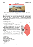
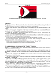
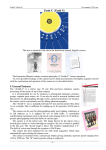
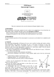
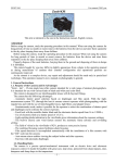
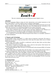
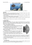
ZORKI-6
User manual, 1960 year
This text is identical to the one in the Instruction Manual, English version, 1960 year.
1. Photographic camera “Zorki-6”
This Instruction Manual contains essential operating principles of the “Zorki-6” camera, and is not
intended as a photographer’s handbook.
Before proceeding to take pictures, study the operation of the camera and its handling instructions
presented in this Manual.
Minor differences between your camera and the present Manual may be due to ever-advancing
development of the camera design.
2. Certificate
The camera is provided with coated lens, type: No.
Relative aperture
Resolution of the camera when used with “Negaitive-M3” film is not lower than:
(a) central lines per 1 mm,
(b) peripheral lines per 1 mm
The camera meets the existing Specifications; it passed all the Inspection Department trials and has
been found fit for service.
For the Inspection Department: (Signature) 196 (Date)
The camera is delivered in complete set (see below).
3. Camera set
1. Camera with lens — 1 piece
2. Magazine with spool — 1 piece
3. Lens cap — 1 piece
4. Carrying case with shoulder strap — 1 piece
5. Instruction Manual with Certificate — 1 copy
I. Purpose
The “Zorki-6” is a modern roll-film minicamera with lever-type shutter setting.
The camera is intended for a wide range of versatile photography; it is used with equal success by
amateur photographers and cameramen.
The lever-type shutter setting mechanism is coupled with both the film transport mechanism and the
picture counting mechanism, so that setting of the shutter automatically advances the film after each
exposure, the picture counter indicating the number of exposures made. This feature of design gives
the “Zorki-6” advantages as compared to earlier models of the “Zorki” family, allowing the operator to
quickly prepare the camera for taking the picture and to make several shots without removing the
camera from the eye.
–1–
ZORKI-6
User manual, 1960 year
II. Description
The camera is fitted with either of the three lenses listed below:
(a) lens “Industar-26M”;
(b) lens “Jupiter-8”;
(c) lens “Industar-50” (Fig. 1), in sliding and fixed mounts.
All these lenses have their advantageous features: the two first lenses possess high (maximum)
rapidity, while the third lens has a somewhat increased resolution all over the picture area.
The lenses are anastigmatic, with coated optical surfaces and inner iris diaphragms.
Focal length — 5 cm.
Angular field of view — 45°.
Relative aperture range:
“Industar-50” lens — 1:3.5; 1:4; 1:5.6; 1:8; 1:11; 1:16;
“Industar-26M” lens — 1:2.8; 1:4; 1:5.6; 1:8; 1:11; 1:16; 1:22;
“Jupiter-8” lens — 1:2; 1:2.8; 1:4; 1:5.6; 1:8; 1:11; 1:16; 1:22.
Minimum focussing range — 1 m.
Working distance of the camera, i.e. distance between the lens end plane and the image plane of
infinitely removed objects, amounts to 28.8 mm.
Mounting diameters for attachments (sun shades, light filters, extension lenses, etc.) are:
for the “Industar-50” lens — 36 mm;
for the “Industar-26M”
and “Jupiter-8” lenses — 42 mm.
Fig. 1
1. Picture counting dial
2. Shutter release button
3. Range-finder object glass, right
4. Shutter mechanism disengaging button
5. Shutter speed dial with index
6. Range-finder object glass, left
7. Film reverse take-up knob
8. Film sort dial
9. Flash synchronizer contacts
10. Lens distance scale
11. Depth-of-field scale
12. Front lens ring with diaphragm scale
13. Diaphragm setting ring
14. Lens focussing lever
15. Delayed-action setting lever
16. Delayed-action release button
17. Eyelet
–2–
ZORKI-6
User manual, 1960 year
Threads for screwed-in attachments (light filters and extension lenses):
in the sliding-mount “Industar-50” lens — 23x0,5 mm; in the “Industar-26M” and “Jupiter-8”
lenses — 40,5x0,5 mm; in the fixed-mount “Industar-50” lens — 33x0,5 mm.
Picture sizes 24 by 36 mm, the camera using 35-mm perforated film.
The camera magazine accommodates 1.65-m length of motion picture film, sufficient for making 36
exposures.
The camera is equipped with a curtain shutter providing for momentary speeds of 1/30; 1/60; 1/125;
1/250 and 1/500th of a second.
Besides, hand-controlled time exposures (with the shutter set opposite letter “B”) and duration
exposures are obtainable.
Exposure speeds may be set with the shutter either set up or released. It should be borne in mind
that the shutter speed dial must be turned over the scale only from letter “П” toward figures 30, 60,
125, 250 and 500, and then back again.
Never rotate the dial with:n the interval between “B” and “500”, as in this instance the
mechanism is likely to be damaged.
The camera shutter is set up by means of a shutter-setting lever linked with the film transport
mechanism and the picture counting mechanism. Shutter is being re-set as the film is advanced for the
next exposure and the picture counting dial travels through one division.
The optical range-finder (base 67 mm) is linked with the focussing system. The optical view-finder
and the range-finder are combined in the same field of view, and have a common eyepiece.
The magazine used with the camera is a split metal piece made absolutely light-proof.
The mounting thread of the camera lens seat is standard for different camera makes and suits all
main and interchangeable lenses used with photographic cameras of the “Zorki” family.
Overall Dimensions of Camera
Width, mm — 135
Height, mm — 80
Length in operating position, mm — 70
The camera can be operated without removing it from the carrying case. The camera (in the case)
can be screwed to a tripod.
The flexible releaser is screwed into the thread provided in the shutter release button. When used,
the flexible releaser reduces the probability of camera shifting caused by the shutter release.
18. Dioptrical adjustment
lever
19. Range- and view-finder
eyepiece
20. Attachment shoe
21. Shutter mechanism
setting lever
Fig. 2
–3–
ZORKI-6
User manual, 1960 year
III. OPERATION
1. Removing, Replacing, Opening and Closing the Camera (Fig. 6)
Rotate the camera stand nut counterclockwise to unscrew it from the camera base plate, and take the
camera from the carrying case.
Pull lock 27 all the way up, and then open back cover 25. Take-up spool 23 will not be removed
from the camera. Magazine 22 yields only after film reverse take-up knob 7 has been brought up. The
camera is closed and replaced in the reverse order. It should be remembered that the camera is
provided with a magazine which is automatically opened inside the camera under the pressure of a pin
fitted in the lower part of the back cover. Therefore, easy locking of the back cover requires that the
botton edge of the camera should be pressed tight against the camera body. Prior to closing the cover
of the carrying case, see that the lens is set at infinity (“∞”), or sunk inside the camera if its
mount is sliding.
2. Magazine Loading (Fig. 3)
The magazine 22 of the “Zorki-6” camera consists of outer casing, inner casing and central spool.
To open and strip the magazine, press off the lock spring until it has cleared its seat and withdraw
the inner casing with spool from the outer casing.
Load and unload magazine by red light or in full darkness, depending on the film sort.
Fig. 3
22. Magazine
Cut the film end as shown in Fig. 4, and insert it into one of the spool slits, from the wider side. As
the spool is held with its head facing inside, the emulsion side of the film faces downward.
Fig. 4
The film end showing on the other side of the slit should be bent and passed into the second slit,
from its narrower side. Then the remaining length of the film end should be bent threefold, and the
film tightened so that the bent end is wedged in the slit. Holding the spool so as to face its head, roll
the film on to it with the emulsion side inward (toward the spool stem), rotating the spool
counterclockwise. Do not attempt to pull the film already rolled on the spool with a view to tightening
–4–
ZORKI-6
User manual, 1960 year
it as the action causes scratches on the emulsion face of the film. The film should be held carefully by
its sides so that no finger-prints are left on its emulsion side.
Fig. 5
Insert the film-loaded spool in the inner casing so that the spool head fits into the opening in the
casing bottom. A 8 to 10-cm length of film end should be left free. Insert the inner casing with the film
spool into the outer casing. The inner casing should be latched inside the outer casing with the locking
spring which enters the recess on the magazine outer casing edge.
After that, the magazine can be handled by daylight.
Note. The “Zorki-6” camera can be used with other types of film magazines, too, provided their
sizes meet the Specifications for the standard magazine delivered with the “Zorki-6” camera set.
3. Camera Loading (Figs. 1, 2, 4)
Prior to loading the camera, make sure that the shutter mechanism is engaged and operative.
See that buttons 2 and 4 are brought to their upward positions. Set the camera shutter by turning
lever 21 as far as it will go. Pull shutter speed dial 5 up and set it at the selected division opposite the
index made on the dial axle. When released, the shutter speed dial should go down to assume position
in which the dial upper surface stands almost level with the index plane.
If the shutter mechanism operates upon pressing shutter release button 2, the camera mechanism is
sound and the camera may be loaded. Pull a 10-cm length of film out of the magazine (Fig. 4), and, if
necessary, cut it accurately by about half the film width. When cutting, see that the cut does not run
through perforation holes. The film end should be cut carefully, without burrs and ruptures involved to
obviate the film stickings in the film guides, or its breaking, which brings about fouling or even failure
of the camera.
Open the camera back cover, secure the film end under the take-up spool spring, and make sure that
the uncut film edge closely fits the spool flange. When the magazine is being inserted in the camera
or removed from it, the film reverse take-up knob should be in its upward position.
Loading or unloading over, lower the reverse take-up knob as far as it will go.
Fig. 6
23. Take-up spool
24. Camera stand nut
25. Back cover
26. Film hold-down
plate
27. Lock
–5–
ZORKI-6
User manual, 1960 year
Close the camera back cover and press the lock downward.
To advance the first unexposed film frame to the frame window, set and release the shutter three
times.
When the shutter is being set, film reverse take-up knob 7 should spin. If the knob fails to revolve,
check the camera for correct loading with film. However, it should be remembered that this is also
likely to take place during the first few film transport cycles if the magazine is loaded with a film
which is much shorter than the normal length. In this case, the reverse take-up knob will begin rotating
only when the film tension on the magazine spool is sufficient.
Rotate picture counting dial 1 (holding it by the knurled surface), to set its zero mark against the
index dot on the camera top surface.
This done, the camera is considered loaded.
Reverse take-up knob 7 mounts film sort dial 8. Holding the film sort dial by its knurled surface and
retaining the reverse take-up knob with the other hand, rotate the film sort dial until the film sort index
stands opposite the dial mark corresponding to the sensitivity of the film used.
The silhouette of a lamp and the sun with rays marked next to the inscription COLOUR
(ЦВЕТНАЯ) identify colour film for artificial and day-light photography. Figures 11, 22, 45, 90 and
180 denote film sensitivities according to the existing system of film sensitivity standards. If, for
instance, the camera is loaded with a black-and-white film of a 65-unit sensitivity, the index should be
set at the corresponding graduation between Figures 45 and 90.
4. Camera Optical System: Lens, Range-Finder, View-Finder (Figs. 1 and 2)
Before taking pictures, study the construction of the camera lens.
The “Industar-50” is of a sliding version; when the camera is not expected to be used, the lens is
drawn into the camera. When slide in, the lens projects from the camera but slightly. To place this lens
in the operating position, pull the lens out holding it by ring 12, and, having fitted the cams in their
recesses, turn the lens clockwise, seeing that it is fixed tight in position, without slightest play
involved.
The “Industar-26M”, “Jupiter-8” and the fixed version of the “Industar-50” do not require the above
mentioned operations, as their mounts are permanently fixed in the camera bodies.
The lens is irised by rotating diaphragm setting ring 13. The desired lens opening figure is set on the
scale provided on ring 12. The lens should be irised before focussing.
For focussing, the lens is rotated in its thread by operating lens focussing lever 14 of the sliding
“Industar-50” lens or the focussing ring of the fixed “Industar-50” lens. In the initial (“∞”) positions,
the lens mounts are locked by a spring-loaded button provided on the focussing lever. To release the
lever for operation, it is necessary to press this button.
The lens travel is limited by stops. Distances to the sharp focussing plane are read off distance scale
10. The distances are indicated by an index with graduations of depth-of-field scale 11 spaced
symmetrically on either side of the index.
Focussing is done with the aid of the optical range-finder. Observing through range-finder
eyepiece 19, lay the lens to the object to be photographed. In this event, the central part of the rangefinder field-of-view shows a yellowish field against a bluish background.
Within the borders of this square field, the object observed is seen double-imaged if the object is
not infinitely distant (any distance less than 100 m).
Objects having sharp contours should be selected for focussing. Turn the lens by the focussing lever
(or the focussing ring) to align the two images of the object.
This done, set the lens accurately for the distance to the object to be photographed, and read this
distance off distance scale 10. This focus setting is sure to produce a sharp picture if the camera is held
firm at the picture-taking moment, and the photographed object is still or moves but not very quickly.
Remember that if the object is located at a distance shorter than 1 m, it is impossible to superimpose
the double images upon each other, and it is vain to use the range-finder.
Sometimes in the photography practice it is either impossible or inconvenient make use of the
range-finder. In such cases, the lens distance setting can be done directly by the distance scale
graduated in meters. The distance to the object to be photographed should be known before or
measured on the spot.
–6–
ZORKI-6
User manual, 1960 year
The view-finder combined with the range-finder in the common field of view provides for
simultaneous framing of the photographed scene. For correct framing, bring your eye as close to
range- and view-finder eyepiece 19 as possible. Apply the eye strictly to the centre of the eyepiece so
that the yellowish-tinted square field is in the centre of the view- and range-finder field-of-view. Nonobservance of this condition brings about poor picture framing.
The camera view-finder is designed for use with normal lenses of 5-cm focal length. All the other
lenses require view-finders with corresponding picture fields, or a multifoc view-finder intended for
use with five different lenses characterized by different focal lenghts. Attachement view-finders are
inserted in shoe 20 provided on the camera top surface.
It is advisable to make use of depth-of-field scale 11 when taking pictures, consisting of paired
graduations symmetrically spaced on either side of the index mark and marked to indicate the lens
opening figures. Two distances within which all objects are produced with sufficient sharpness on the
picture are always read against these graduations on distance scale 10; these two limiting distances are
called the close and far limits of the depth of field.
It may happen that the photographer must be ready to take a picture at any unexpected moment. In
such cases, the lens should be irised close (for example, to relative aperture of 1:16), and the distance
should be set so that the far limit of depth of field is “∞” (one of the “16” graduations of depth-of-field
scale 11 being aligned with mark “∞” of distance scale 10). In this instance, the other identicallymarked graduation of the depth-of-field scale will show the close depth-of-field limit, i.e. the shortest
distance by which the photographer can approach the object photographed to obtain sharp picturing of
the latter.
5. Flash Synchronizer (Fig. 1)
Flash synchronizer contacts 9 are intended for operating the shutter at the moment of the flash.
When an electronic (multiple-action) flash is used, the plug of the flash unit connecting wire should
be inserted in the connector socket of the synchronizer contact marked with a lightning symbol. The
flash circuit will be closed the moment the frame window gets fully opened.
Only shutter speeds of l/30th of a second and slower and hand-controlled long time exposures may
be us!ed when employing flash synchronizer to contacts.
When single-action flash bulbs are used, the flash unit connecting wire should be plugged in the
synchronizer contact marked with a silhouette of an electric bulb. The flash circuit in this case will be
closed with a delay required for the flash bulb to gain the required luminous power.
6. Automatic Releaser (Self-Timing Device)
“The “Zorki-6” is provided with a self-timing device which is used whenever it is desired that the
picture is taken with a delay and without direct operation of the photographer. Thus, when the
photographer is taking his own picture in a group portrait, he mounts and lays the camera, cocks up the
shutter and sets the self-timing device; then the photographer actuates the delayed-action mechanism,
having enough time to take his place in the group to be photographed.
Setting the Automatic Releaser for Operation
Set up the shutter and move the delayed-action setting lever all the way counterclockwise.
Then, press the delayed-action release button at the desired moment for the shutter to be
automatically released with a 9 to 15-second delay. Upon the shutter release action, the delayed-action
setting lever returns to its initial position. The shutter can be set up both with the set and released selftiming device. However, it is recommended first to set the shutter and the selected shutter speed, and
only then to wind up the self-timing device.
To avoid undue wear of the self-timing device spring, it is advisable to wind it up only when
required; in all other cases it should be kept released. Should the shutter speed dial be set opposite
letter “B”, the exposure speed, with the self-timing device in operation, will be not faster than one
second. As this exposure time varies for different cameras, it is advisable to check it with the aid of a
stopwatch.
The self-timing device of the “Zorki-6” camera can be operated together with a flash unit.
7. Taking the Picture (Figs. 1 and 2)
When preparing to take a picture:
1. Load the camera. If it was loaded and several exposures have already been taken, look at the
–7–
ZORKI-6
User manual, 1960 year
picture counter to see if there is unexposed film left. Make sure the shutter mechanism is engaged.
2. Remove the cap from the lens. If the camera is fitted with a sliding lens, draw it out and lock for
operation.
3. Set the lens opening as dependent on the desired depth of field. If necessary, fit a light filter or
lens shade on the lens.
4. When taking flash pictures, connect the flash unit to the camera, and check for reliable plugging.
5. Set the shutter by turning shutter-setting lever 21 as far as it will go.
6. Determine the required exposure and set the exposure speed by pulling shutter speed dial 5 up
and positioning it opposite the desired division. When released, the dial should sink down and be fixed
in the selected position, the dial top surface being almost level with the index.
The shutter speed may be set either before or after setting the shutter mechanism. Bear in
mind that it is prohibited to rotate shutter speed dial 5 in the “B” to “500” interval.
7. Observing through view-finder eyepiece 19, lay the camera on the object to be photographed.
Take a position off the object to obtain adequate framing of the photographed object within the viewfinder field.
8. Focus the lens operating the range-finder mechanism.
9. Take the shot by smoothly pressing the shutter release button to prevent jerking of the camera.
This procedure is true for instantaneous exposures, when the camera is hand-held and no flexible
releaser is used.
When taking the picture with the camera in the carrying case, see that the camera case cover does
not get between the object and the lens. This should be remembered especially when photographing
with the camera held vertically.
8. Hand-Controlled and Endurance Exposure Setting
To obtain a hand-controlled shutter speed, letter “B” marked on the shutter speed dial should be
brought against the shutter speed setting index. In this position, the shutter remains opened as long as
shutter release button 2 is held depressed.
The same shutter speed dial setting (at “B”) produces considerably delayed (endurance) exposures.
For this purpose, shutter release button 2 should be fixed in the depressed position by turning the
button all the way counterclockwise. In this position, the shutter remains opened. To release the
shutter, turn the button in the opposite direction and let go of it.
9. Camera Unloading
After making approximately 36 exposures, the shutter-setting lever will resist rotation and stop the
shutter operation. This means that the whole of the film has been exposed and it is time to re-spool it
back to the magazine.
Cover the lens with the cap, and holding button 4 depressed, rotate reverse take-up knob 7 in the
direction of the arrow until the spring of the take-up spool produces the film (this is indicated by the
effort applied for extracting the film from the take-up spool).
Open the camera back cover having lifted the reverse take-up knob, and remove the magazine with
the exposed film. Keep the magazine closed and intact until the film is to be developed. Having respooled the film, set and release the shutter to check the work of the mechanism. This done, the
camera is again ready for loading.
http://eugigufo.net/download/photovideo/
–8–