1
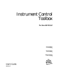
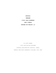
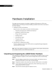
HI-WAVE
ICD
Target Interface
© Copyright 1998 HIWARE
HI-WAVE
Product Manual
Manual Date
HI-WAVE - ICD
12/98
© Copyright 1998 HIWARE
HI-WAVE
3
Contents
IMPORTANT. . . . . . . . . . . . . . . . . . . . . . . . . . . . . . . . . . 5
NT Installation Notice . . . . . . . . . . . . . . . . . . . . . . . . . . . 5
ICD Target Interface . . . . . . . . . . . . . . . . . . . . . . . . . . . . 7
Introduction . . . . . . . . . . . . . . . . . . . . . . . . . . . . . . . . . . . . . . . . . . . 7
Interfacing Your System and ICD . . . . . . . . . . . . . . . . . . . . . . . . . . 8
Loading the ICD Target Component . . . . . . . . . . . . . . . . . . . . . . . . 9
Default Target Setup . . . . . . . . . . . . . . . . . . . . . . . . . . . . . . . . . . . 10
ICD Default Environment . . . . . . . . . . . . . . . . . . . . . . . . . . . . . . . . . . . . . . . . . . . 10
Command Files and ICD commands . . . . . . . . . . . . . . . . . . . . . . . . . . . . . . . . . . 12
Memory Configuration. . . . . . . . . . . . . . . . . . . . . . . . . . . . . . . . . . 17
System Configuration for a CPU32 . . . . . . . . . . . . . . . . . . . . . . . . . . . . . . . . . . . 18
System Configuration for a CPU16 . . . . . . . . . . . . . . . . . . . . . . . . . . . . . . . . . . . 20
Examples of “Reset.cmd” File . . . . . . . . . . . . . . . . . . . . . . . . . . . . . . . . . . . . . . . 21
Board Configuration for the MPFB1632 . . . . . . . . . . . . . . . . . . . . . . . . . . . . . . . 24
References . . . . . . . . . . . . . . . . . . . . . . . . . . . . . . . . . . . . . . . . . . . 27
© Copyright 1998 HIWARE
HI-WAVE
4
© Copyright 1998 HIWARE
HI-WAVE
IMPORTANT
IMPORTANT
NT Installation Notice
In order to access the parallel port of a Host running Windows NT, a special driver
has to be installed.
To install this driver, after installing the HIWARE Development Kit on the Host,
run the setup program called “icd_dr.bat“. This program is located in the directory “prog\drivers\Nt\ICD“ in the HIWARE installation on the Host.
You can also run this program from the “ICD driver setup” folder in your
installation group or choose from Windows Taskbar “Start | Programs | Hiware |
ICD driver setup | Win NT driver”.
© Copyright 1998 HIWARE
© Copyright 1998 HIWARE
ICD Target Interface
7
ICD Target Interface
Introduction
Another advanced feature of HI-WAVE for the embedded system development
world is the ability to load different framework targets. The ICD Background
Debug Interface is introduced in this document.
The ICD is an interface developed by P&E Microcomputer Systems and used by
HI-WAVE to communicate with an external system also called target system.
With this interface, you can download an executable program from the HI-WAVE
environment to an external target system based on a Motorola MCU which will execute the program. You will also have the feedback of the real target system behavior
to HI-WAVE.
HI-WAVE will fully supervise and monitor the MCU of the target system i.e. control the CPU execution. You can read and write in internal/external memory when
the MCU is in Background Mode. You have full control over the CPU state with the
possibility to stop execution, to proceed in single step mode and to set breakpoints
in the code.
Note: The ICD target component is not included in the HI-WAVE base installation.
© Copyright 1998 HIWARE
HI-WAVE
8
Interfacing Your System and ICD
Interfacing Your System and ICD
A parallel to serial interface is used for the communication between ICD target and
host computer. The communication to the target is serial. The communication protocol between the ICD and host is fully handled by the ICD Target driver which is
automatically loaded with the ICD Target Component.
The Centronics (printer) cable must be as short as possible (if not completely
removed) between the host and the ICD interface to avoid communication
troubleshoutings.
LPT n
parallel communication
ICD Link
Printer Cable
ICD cable
Host Computer
© Copyright 1998 HIWARE
Target System
serial communication
HI-WAVE
ICD Target Interface
9
Loading the ICD Target Component
Usually the target is set in the PROJECT.INI file, where Target=Icd (please
see also next section). The ICD driver detects automatically that the ICD is connected to your system. However, if nothing is detected, an error message pops up
and informs you that the target is not connected or is connected to a different port.
If no target is set in the PROJECT.INI file or if a different target is set, you can
load the ICD driver selecting Component | Set Target... in the main menu as shown
below and choose Icd in the list of proposed targets.
After a successful target loading, the Target menu item is replaced by ICD.
Selecting Icd | Force BDM triggers a reset of the target, forces the CPU into background mode and executes the command files “forcebdm.cmd” and
“reset.cmd”. (See section Command Files).
Selecting Icd | Reset triggers a reset of the target and executes the command file
“reset.cmd”.
Choose Icd | Load.. to load an executable file (“.abs”) into the memory of the target. The program counter will point at the first instruction of the startup section.
© Copyright 1998 HIWARE
HI-WAVE
10
Default Target Setup
Default Target Setup
As any other target, the ICD target component can be loaded from the Target menu
or can be set as a default target in the PROJECT.INI file which should be located
in the working directory.
Example of PROJECT.INI file:
Window0=Source
Window1=Assembly
Window2=Procedur
Window3=Register
Window4=Memory
Window5=Data
Window6=Command
Target=ICD
0
60
0
60
60
0
0
0
0
30
30
60
55
78
60
40
60
40
40
60
60
30
30
25
30
40
23
22
ICD Default Environment
As any HI-WAVE program, the ICD target component parameters can be set in the
DEFAULT.ENV file which should be located in the working directory.
Under normal usage, these parameters are once interactively set at installation in the
DEFAULT.ENV file and used in future debugging sessions.
The environment variables associated to the ICD target component are introduced
below.
ICDPORT
This variable is used to specify (to the host) the parallel communication port where
the ICD is connected.
Syntax
ICDPORT=LPTn
ICDPORT=LPTn:
ICDPORT=portAddr
where
n: number of used printer port (1,2)
© Copyright 1998 HIWARE
HI-WAVE
ICD Target Interface
11
portAddr: address of used printer port (1,2). The possibility to specify the
address of the used printer port is only possible with Windows 95 and Windows
3.1x with Win32s. Under Windows NT, the access to a port has to be handled by a
driver which evaluates the address of the specific port itself. Therefore it is not possible to specify a port address. Do first try to define the Icd-Port by name, e.g. LPT1
or LPT2. Define the communication port by address only if it is necessary (when
not possible by name).
Examples ICDPORT=LPT2
//Name of the port.
Examples ICDPORT=0x378
//Address of the port.
Default ICDPORT=LPT1
Note: ICDPORT=0x378 is the MS-DOS 1st parallel printer port address and
ICDPORT=0x278 is the MS-DOS 2nd parallel printer port address. It
could be necessary to specify the ICD port by address under some Win 3.x
installations.
BMDELAY
This variable is used to slow down the communication speed of the serial link (ICD
cable). The maximum speed available is given by the MCU clock speed, but the
communication speed depends also on the PC. So if your target MCU is running
with a clock speed below 1 MHz, then you may have to define a delay that is bigger
than 0.
Syntax
BMDELAY=x
where
x: communication delay. Value counted from 0, where 0 is the fastest available
speed.
Example BMDELAY=9
You may have to try different values, starting from a high value (e.g. 150, 100, ...)
until you find the optimal value for your system.
Default Default value is 0.
© Copyright 1998 HIWARE
HI-WAVE
12
Default Target Setup
Command Files and ICD commands
For configuring the ICD target for a specific MCU and memory configuration, there
are also some hints to consider. For the target initialisation a startup file “startup.cmd” is executed, when the ICD driver is loaded. Another command file
“reset.cmd” is executed, when a reset has been triggered by the User selecting
Icd | Reset. When the user selects Icd | Force BDM the command files
“forcebdm.cmd” and “reset.cmd” are executed.
The general Syntax of Command files is described in [CMDL]. Here are the commands that are defined for the ICD target component:
ADRSPACE
(for CPU32 only)
Syntax ADRSPACE <address space> | RESET
Where <address space> is a value from 0 to 7.
This command allows to specify the address space which will be used for all memory accesses which will be done until another ADRSPACE command specifies a
new value.
Executing any target code or a reset will set the default address space which is
supervisor code (e.g. run, trace, reset, ...) i.e. [FC2:FC0]=110.
If RESET is specified, the previous value will be used again. This will allow to temporary change the address space and reset it again.
Address space encoding:
[FC2:FC0]=000
[FC2:FC0]=001
[FC2:FC0]=010
[FC2:FC0]=011
[FC2:FC0]=100
[FC2:FC0]=101
[FC2:FC0]=110
[FC2:FC0]=111
(0): Undefined, reserved for future use by Motorola
(1): User Data Space
(2): User Program Space
(3): Undefined, reserved for user definition
(4): Undefined, reserved for future use by Motorola
(5): Supervisor Data Space
(6): Supervisor Program Space
(7): CPU Space
Note: This command is available for CPU32 only. Please refer also to CPU32
Reference Manual from Motorola, section Processing States, Types of
Address Space.
© Copyright 1998 HIWARE
HI-WAVE
ICD Target Interface
13
CATCHTRAPS
Goes in background mode when an exception is triggered. This command is used to
catch interrupts and force the system to enter in background mode. There the
actived interrupt can be retrieved.
Syntax
CATCHTRAPS <firstVec> <lastVec> [<address>]
where
<firstVec>: First interrupt vector captured
<lastVec>: Last interrupt vector captured
<address>: Address of the BGND instruction where the first vector points to. If
no address is specified, a default address is chosen: The default for the HC16 is the
address 0x200 and, for the CPU 32, a reserved space in the vector table (vector no.
16 up to 23) is used (vector base register + 0x48).
Example (HC16) CATCHTRAPS 4 20 0x4300
The HC16 reserves the vector numbers from 0 to 3 for initial values (for
ZK,SK,PK,PC,SP,IZ) after reset. So don’t overwrite them with CATCHTRAPS.
At address 0x0000:
XXXX XXXX XXXX XXXX 4300 4304 4308
The interrupt vectors are pointing now to the new defined interrupt handlers.
At address 0x4300:
37A6 2777 37A6 2777 37A6 2777
For the HC16, for every interrupt vector, an own interrupt function (37A6 2777 =
BGND RTI) is placed in the section specified with the address argument of
CATCHTRAPS. The interrupt vector number is calculated by dividing the difference of the location address where the MCU halted (BGND instruction) and the
address of the catch section specified, by 4. Assuming the MCU halted with BGND
at 0x4308 in our example, we get (0x4308 - 0x4300) /4 = 2. The first vector
catched was 4, so we know that the trap with vector number 6 (4+2) was triggered.
Example (CPU32) CATCHTRAPS 2 20 0x4300
The CPU reserves the vector numbers from 0 to 1 for initial values (for SP, PC)
after reset. So don’t overwrite them with CATCHTRAPS.
At address 0x0000:
XXXX XXXX XXXX XXXX 0000 4300 0000
The interrupt vectors are pointing now to the new defined interrupt handlers.
© Copyright 1998 HIWARE
HI-WAVE
14
Default Target Setup
At address 0x4300:
4AFA 4E73
XXXX XXXX XXXX XXXX
For the CPU32, only one catch routine (BGND RTE) is placed at the address specified. All interrupt vectors point to this same location. The interrupt vector is
retrieved from the stackframe of the interrupt call.
FORCEBDM
Forces the target processor into Background Debug Mode (BDM).
This also resets the processor and the target system. After reset, the command files
FORCEBDM.CMD followed by RESET.CMD are executed.
RESET
Syntax
RESET
Triggers a reset of the target and executes the “reset.cmd” command file. The
command is equivalent to selecting Icd | Reset.
Please don’t issue a reset directly on the target, because the driver software does not
notice it. Click Icd | Force BDM to reset the target and lead it back to your customized configuration by executing the reset command file.
The command has no argument.
TERMINAL
Install a terminal emulation for the standart IO of the target.
The terminal emulation is used to redirect the output of the target MCU to the output of the terminal component and to redirect the input on the Terminal component
into an input buffer of the target memory that is used as input by the MCU. The Terminal emulation is based on a simple protocol for data exchange between the target
MCU and the ICD driver. For the target application, the frame for data exchange is
at a fixed address. For the ICD driver the address of the frame is defined at the
address passed with the argument of the TERMINAL command. So the argument
of the TERMINAL command depends on what address the target application
expects the protocol frame to be installed at.
Syntax
TERMINAL [<address>]
where
<address>: Address, where the terminal emulation (protocol frame) is installed.
© Copyright 1998 HIWARE
HI-WAVE
ICD Target Interface
15
A value of 0 disables the terminal emulation.
How to use the Terminal component
+ Open the “Terminal” component with Component | Open | “Terminal”
+ Load the target application.
+ Execute “TERMINAL <address>” in the Command Line component window.
Note: Currently, this command is executed from “reset”, “startup” and
“forcebdm” files.
+ Start the application
+ The IO of a target application, that fits the protocol like the delivered example
“termbgnd.c” is now redirected to the terminal.
Note: When using the Calculator “calcbgnd.abs” program, the Terminal component must be opened first.
Protocol Frame
offset size comment
0
1
flag: !=0 -> char from terminal
1
1
character from terminal
2
2
0x5A5A :- string is written
0xA5A5 :- terminal is initialised
4
4
Address of string to receive.
Protocol
0. Terminal initialisation (command TERMINAL <adr>)
ICD Driver
Target application
writes 00 00 A5 A5 at <adr>
1. Target application writes a string to the terminal output
ICD Driver
Target application
polls <adr>+2 for A5A5
writes the address of the string buffer at <adr>+4
writes 5A 5A at <adr>+2
© Copyright 1998 HIWARE
HI-WAVE
16
Default Target Setup
polls <adr>+2 for 5A5A
gets string address at <adr>+4
reads the string
sends the string to terminal output
writes 5A 5A at <adr>+2
2. Target application reads a character from terminal input
ICD Driver
Target application
Polls until byte at <adr> == 0
Writes terminal character at <adr>+1
Writes 01 at <adr>
polls <adr> until byte at <adr> != 0
reads the byte from <adr>+1
resets the flag at <adr> to 0
Note: As the ICD driver and the target MCU exclude each other from access to the
target memory by switching into BDM mode and back, this protocol is safe
at the condition that the target application is running correctly and the
memory space involved is not modified by the interacting user when the target is in background mode.
VER
Shows the version of all opened components including the ICD target.
Syntax
VER
This command has no argument.
© Copyright 1998 HIWARE
HI-WAVE
ICD Target Interface
17
Memory Configuration
After a reset, only the boot chip select (CSBOOT) is configured. In order to access
other memories, the chip select logic of the MCU has to be configured. This will
normally be done by the startup code of your application. But for debugging, this
needs to be done after each reset to allow you to load your application. For an
appropriate configuration of chip selects for access to the external devices, you
write your own startup and reset command files (“startup.cmd” and
“reset.cmd”). Use the commands
WB
<address>
<value>
//write byte
WW
<address>
<value>
//write word (16 bit)
WL
<address>
<value>
//write long (32 bit)
Note: Delivered command files match to the Motorola board default settings. (e.g.
MPFB1632 board with 2 pseudo-ROM (RAMs) of 32k and no SRAM or
FLASH. They are also adapted to MPB332AB boards supporting the
MC68332, which as an internal 2kB RAM, and MPB16Y1B board supporting HC16Y1 which as also an internal 2kB RAM.
Take a look at the delivered command files in your installation directory. Here is a
short explanation of the most important system registers. Refer the manual of your
MCU for a detailed description (See [MC68332] for CPU32 and [MC68HC16] for
CPU16).
Note: Each MCUs version has its own memory mapping. Software and hardware
chip selects have to be done according to the MCU hardware and external
hardware, i.e. ROM (pseudo-ROM), RAM (e.g. FLASH, SRAM), etc.
© Copyright 1998 HIWARE
HI-WAVE
18
Memory Configuration
System Configuration for a CPU32
Important Registers of the SIM (System Integration Module):
SYPCR (byte) at 0xFFFA21
- The System Protection Control Register. Specifies the Software watchdog disabling (BME=0) /enabling (BME=1), the watchdog timeout (bits SWT0/1) and some
flags for bus monitoring. A watchdog trap (RESET) is issued when the MCU is
running without periodically invoking a defined action, as for example reinitialising
a dedicated register. For the CPU32 this is the SSR register, where first 0x55 and
the 0xAA is written to. Watchdogs are implemented for stopping and reseting a
MCU that is trapped in a loop or lost.
SYNCR
at 0xFFFA04
- Synthesizer control: Specifies the operation frequency related to the crystal.
MCR
at 0xFFFA00
- The module configuration register controls the SIM configuration
CSPAR0
at 0xFFFA44
CSPAR1
at 0xFFFA46
- The pin assignement registers (CSPAR0/1) enable or disable chip select and determine the signals triggered on an access over a disabled chip select. Together with
the assignements to the option register of a chip select (CSORBT for boot chip
select and CSORB0,..,CSORB10 for the access to memory banks) can be fully configured.
Each chip select has its own associated base register. The Registers CSBART for
the boot block and CSBAR0,..,CSBAR10 for the other memory blocks. The following list summarises all base address and option registers:
CSBARBT/CSORBT
at 0xFFFA48
CSBAR0/CSOR0
at 0xFFFA4C
CSBAR1/CSOR1
at 0xFFFA50
CSBAR2/CSOR2
at 0xFFFA54
CSBAR3/CSOR3
at 0xFFFA58
CSBAR4/CSOR4
at 0xFFFA5C
CSBAR5/CSOR5
at 0xFFFA60
© Copyright 1998 HIWARE
HI-WAVE
ICD Target Interface
19
CSBAR6/CSOR6
at 0xFFFA64
CSBAR7/CSOR7
at 0xFFFA68
CSBAR8/CSOR8
at 0xFFFA6C
CSBAR10/CSOR10
at 0xFFFA74
© Copyright 1998 HIWARE
HI-WAVE
20
Memory Configuration
System Configuration for a CPU16
The register naming is the same for the CPU16 and CPU32:
SYPCR
(byte)
at 0xFFA21
SYNCR
at 0xFFA04
MCR
at 0xFFA00
CSPAR0
at 0xFFA44
CSPAR1
at 0xFFA46
CSBARBT/CSORBT
at 0xFFA48
CSBAR0/CSOR0
at 0xFFA4C
CSBAR1/CSOR1
at 0xFFA50
CSBAR2/CSOR2
at 0xFFA54
CSBAR3/CSOR3
at 0xFFA58
CSBAR4/CSOR4
at 0xFFA5C
CSBAR5/CSOR5
at 0xFFA60
CSBAR6/CSOR6
at 0xFFA64
CSBAR7/CSOR7
at 0xFFA68
CSBAR8/CSOR8
at 0xFFA6C
CSBAR10/CSOR10
at 0xFFA74
© Copyright 1998 HIWARE
HI-WAVE
ICD Target Interface
21
Examples of “Reset.cmd” File
for the MC68HC16Y1
// This file is executed at the startup of HI-WAVE when running
// the ICD debugger. It initializes some on chip registers of the
// HC16 to enable accesses to internal and external memory devices.
// It also contains commands to catch all the possible interrupts
// and traps by setting up all the entries in the vector table
// to point to a BGND instruction.
// Initialization file for the MPFB1632 evaluation board (Modular Platform
// Board) with two HM62256 RAM devices installed on U2 and U4B sockets
// as pseudo-ROM with "word" addressing size.
Note that this is the default
// MPFB1632 board configuration.
// Only boot cs (chip select) is used.
// On chip (internal) 2 K RAM of the MC68HC16Y1 is used as SRAM.
// To modify cs and the memory map, please refer to "MC68HC16Y1 Technical
// Summary" from
// Motorola, section "Chip Selects".
// For further board details and hardware modifications, please refer to
// M68MPFB1632 MODULAR PLATFORM BOARD USER'S MANUAL from MOTOROLA.
// Force Background Mode
// Reset the processor and enter
// background mode
ww
0xFFA20
0x0004
// System protection
ww
0xFFA04
0x7F00
// Synthesizer control
ww
0xFFA00
0x40CF
// Module configuration
//
// Initialize chip select logic
//
// ROM emulation
[0x0000..0x3FFF]
(word accessible only) 16kB
// SRAM
[0x4000..0x47FF]
2kB
//
// Chip select logic setup
// ROM Emulation (Pseudo ROM) located at [0x0000..0x3FFF] (word access only)
ww
0xFFA44
0xFFFF
// CSPAR0
ww
0xFFA46
0xFFFF
// CSPAR1
ww
0xFFA48
0x0002
// CSBARBT 16kB pseudo-ROM block
ww
0xFFA4A
0x7B70
// CSORBT default setup
wl
0xFFA4C
0x00000000
// cs0 : Not used
wl
0xFFA50
0x00000000
// cs1 : Not used
wl
0xFFA54
0x00000000
// cs2 : Not used
© Copyright 1998 HIWARE
HI-WAVE
22
Memory Configuration
wl
0xFFA58
0x00000000
// cs3 : Not used
wl
0xFFA5C
0x00000000
// cs4 : Not used
wl
0xFFA60
0x00000000
// cs5 : Not used
wl
0xFFA64
0x00000000
// cs6 : Not used
wl
0xFFA68
0x00000000
// cs7 : Not used
wl
0xFFA6C
0x00000000
// cs8 : Not used
wl
0xFFA70
0x00000000
// cs9 : Not used
wl
0xFFA74
0x00000000
// cs10: Not used
// Initialize the on chip SRAM (above the 16 kB of pseudo-ROM)
// on chip 2k RAM above the 16k ROM block i.e. located at [0x4000..0x47FF]
ww
0xFFB00
0x8000
// TRAMMCR: disable the SRAM
ww
0xFFB04
0x0040
// TRAMBAR: A14 as cs (mapping), above 16k ROM
ww
0xFFB00
0x0000
// TRAMMCR: enable the SRAM
// Initialize RESET vectors: Initialization of some registers
//ww
0x0000
0x0000
//ww
0x0002
0x0600
//ww
0x0004
0x7FFE
//ww
0x0006
0x0000
// N.B. Initialised in “.prm” file
//
RS
TERMINAL
13
0
0x12
// terminate dynamic link (0 => A6)
// initialize terminal emulation
for the MC68332
// This file is executed at the startup of HI-WAVE when running
// the ICD debugger. It initializes some on chip registers of the
// MC68332 to enable accesses to internal and external memory devices.
// It also contains commands to catch all the possible interrupts
// and traps by setting up all the entries in the vector table
// to point to a BGND instruction.
// Initialization file for the MPFB1632 evaluation board (Modular Platform
// Board) with two HM62256 RAM devices installed on U2 and U4B sockets
// as pseudo-ROM with "word" addressing size.
Note that this is the default
// MPFB1632 board configuration.
// Only boot cs (chip select) is used.
// On chip (internal) 2 K RAM of the MC68332 is used as SRAM.
// To modify cs and the memory map, please refer to "MC68332 Technical
// Summary" from
// Motorola, section "Chip Selects".
// For further board details and hardware modifications, please refer to
© Copyright 1998 HIWARE
HI-WAVE
ICD Target Interface
23
// M68MPFB1632 MODULAR PLATFORM BOARD USER'S MANUAL from MOTOROLA.
// Force Background Mode
// Reset the processor and enter
// background mode
ww
0xFFFFFA20
0x0006
// SYPCR, System protection
ww
0xFFFFFA04
0x7F00
// SYNCR, Synthesizer control
ww
0xFFFFFA00
0x42CF
// MCR, Module configuration
//
// Initialize chip select logic
//
// ROM emulation
[0x0000..0x3FFF]
(word accessible only) 16kB
// SRAM
[0x4000..0x47FF]
2kB
//
// Chip select logic setup
// ROM Emulation (Pseudo ROM) located at [0x0000..0x3FFF] (word access only)
ww
0xFFFFFA44
0xFFFF
// CSPAR0, Chip select and pin assignment
ww
0xFFFFFA46
0xFFFF
// CSPAR1, Chip select and pin assignment
ww
0xF7FFFA48
0x0002
// CSBART, Boot cs
ww
0xF7FFFA4A
0x7b70
// CSORBT, Boot cs options
16k block
(default)
// CSBAR0/CSOR0-CSBAR10/CSOR10
wl
0xFFFFFA4C
0x00000000
// cs0 : Not used
wl
0xFFFFFA50
0x00000000
// cs1 : Not used
wl
0xFFFFFA54
0x00000000
// cs2 : Not used
wl
0xFFFFFA58
0x00000000
// cs3 : Not used
wl
0xFFFFFA5C
0x00000000
// cs4 : Not used
wl
0xFFFFFA60
0x00000000
// cs5 : Not used
wl
0xFFFFFA64
0x00000000
// cs6 : Not used
wl
0xFFFFFA68
0x00000000
// cs7 : Not used
wl
0xFFFFFA6C
0x00000000
// cs8 : Not used
wl
0xFFFFFA74
0x00000000
// cs10: Not used
// Initialize the on chip SRAM (above the 16 kB of pseudo-ROM)
// on chip 2k RAM above the 16k ROM block i.e. located at [0x4000..0x47FF]
ww
0xFFFFFB00
0x8000
// RAMMCR, disable the SRAM
ww
0xFFFFFB04
0x0040
// A14 as cs (mapping), above 16k ROM
ww
0xFFFFFB00
0x0000
// enable the SRAM
//
RS
TERMINAL
14
0x40
© Copyright 1998 HIWARE
0
// terminate dynamic link (0 => A6)
// initialize terminal emulation
HI-WAVE
24
Memory Configuration
Board Configuration for the MPFB1632
Our reference board is the MPFB1632 from Motorola (See the User’s Manual
[MPFB1632]).
Note: All settings shown below are the MPFB1632 Motorola default settings.
ps
RAM/ROM
MCU
ps1
ICD
ps2
co
ps := power supply
s1 := serial interface
s2 := serial interface
ICD := ICD interface, where to connect the ICD cable.
RAM / ROM := external memory
MCU := target mcu
CO := orientation corner to connect the MCU on the bo
socket := socket, where the MCU is fixed on.
First of all check if all jumpers for the appropriate chip selects on the board are set
correctly. There are two jumpers that allow to configure your external memory. On
the Board you will find a bank of jumpers with 13 * 3 pins (see figure below)
1 2 3
CSBOOT
CS0
CS1
CS2
CS3
CS4
CS5
CS6
CS7
CS8
CS9
CS10
FAST PSEUDO
RAM ROM
Two jumpers have to be set for chip selects: CSBOOT at [2,3] that selects the Boot
ROM bank and CS1 at [1,2] for eventual flash RAMs installed on the board. Other
configurations are made by writing the pin assignement registers (CSPAR0 and
CSPAR1 - See section Memory Configuration with Command Files).
For the configuration of the reference board type, the jumper bank shown below has
© Copyright 1998 HIWARE
HI-WAVE
ICD Target Interface
25
to be set in the following way:
1 2 3
RD0
RD1
RD2
RD3
RD4
RD5
RD6
RD7
RD8
RD9
RD10
RD11
RD12
RD13
RD14
RD15
H
W6
L
Note: This seting of the jumpers is specific for the reference board type and changes
from board type to board type. See in the manual of your board for the appropriate setting of the switches.
For memory type and memory size configuration the following jumper configuration figured in the 2 pictures below has to be set:
W1 (DATA MEMORY, RAM SIZE)
W2 (PSEUDO ROM, PIN 1 SELECT)
W3 (PSEUDO ROM, PACKAGE SIZE)
W4 (PSEUDO ROM, PORT SIZE)
W5 (PRU OE (ALL), SELECT)
:= [2,4] [1,3]
:= [1,2]
:= [1,2]
:= [1,2]
:= [1,2]
W7 (U3-WE)
W8 (U1+U3)
W11 (U3-WE)
W10 (MEMORY TYPE)
W12 (MEMORY SIZE)
:= SET
:= SET
:= SET
:= [1,2] = RAM
:= [1,2] = 32K * 8
W13 (VPP / VPPMCU)
W18 (PSEUDO ROM, WRITE PROTECT)
W19 (A19 DISCONNECT)
:= SET
:=SET
:= [1,2] = LOGIC LOW
W21 (+5VB SELECT)
W22 (CPU TYPE)
© Copyright 1998 HIWARE
:= SET
:= [1,2] for CPU16 and [2,3] for CPU32
HI-WAVE
26
Memory Configuration
NOT USED FOR ICD
1
2
NOT USED FOR ICD
1
1
W15-W17
W20
W23
© Copyright 1998 HIWARE
W15
W16
W17
2
1
VSTBY
MODCLK
BERR
15
16
W20
15
16
W23
HI-WAVE
ICD Target Interface
27
References
[MC68332]
MC68332 SIM, System Integration Module, User’s Manual
Motorola INC., 1989
[MC68HC16] Refer to the technical manual of your CPU16
[CMDL]
Manual for the Command Component
[MPFB1632] M68MPFB1632, Modular Platform Board, User’s Manual
Motorola INC., 1993/94
© Copyright 1998 HIWARE
HI-WAVE
28
© Copyright 1998 HIWARE
References
HI-WAVE