1
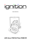
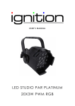
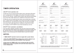
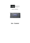
USER M ANUAL
Showtime Face WW
SHOW TIME FACE WW
Table of contents
1.
Safety instructions ................................................................................................
................................
........................................................... 3
1.1.
FOR SAFE AND EFFICIENT OPERATION ................................................................
............................................ 3
2.
Introduction ................................................................................................................................
................................
...................................... 4
3.
Front view of the base ................................................................................................
................................
..................................................... 4
4.
Rear view of the base ................................................................................................
................................
...................................................... 5
5.
Installing the face on the base ................................................................................................
......................................... 5
6.
Menu description ................................................................................................
................................
............................................................. 6
6.1.
Program: ................................................................................................................................
................................
.................................. 6
6.2.
Coolmode ................................................................................................................................
................................
................................ 6
6.3.
DMX Setup ................................................................................................
................................
.............................................................. 6
6.4.
Master Dimmer ................................................................................................
................................
........................................................ 7
6.5.
DMX Signal ................................................................................................
................................
.............................................................. 7
6.6.
Setup Display................................
................................................................................................
........................................................... 7
6.7.
Key Lock ................................................................................................................................
................................
.................................. 7
6.8.
Master Slave on or off ................................................................................................
............................................. 8
6.9.
Setup
etup the dimming Curve ................................................................................................
........................................ 8
6.10.
Version................................................................................................................................
................................
..................................... 8
6.11.
LED PCB Temperature ................................................................................................
............................................ 8
6.12.
Update the software ................................................................................................
................................
................................................ 9
6.13.
Reset ................................................................................................................................
................................
....................................... 9
7.
DMX Charts and Modes ................................................................................................
................................
.................................................. 9
8.
Technical data ................................................................................................................................
................................
................................. 9
2 / 10
SHOW TIME FACE WW
1. Safety instructions
•
This device is suitable for indoor use only.
•
All modifications to the device will void the warranty.
•
Repairs are to carry out by skilled personnel only.
•
Use only fuses of the
he same type and original parts as spare parts.
•
Protect the unit from rain and humidity to avoid fire and electric shocks.
•
Make sure to unplug the power supply before opening the housing.
1.1. FOR SAFE AND EFFICIENT OPERATION
Be careful with heat and extreme temperature
Avoid exposing it to direct rays of the sun or near a heating appliance.
Not put
ut it in a temperature bellow 32°F
32 / 0°C, or exceeding 131°F / 55°C.
Keep away from humidity, water and dust
Do not place the set in a location with high humidity or lots of dust.
Containers with water should not be placed on the set.
Keep away from sources of hum and noise
Such as transformer motor, tuner, TV set and amplifier.
To avoid placing on un-stable
stable location
l
Select a level and stable location to avoid vibration.
Do not use chemicals or volatile liquids for cleaning
Use a clean dry cloth to wipe off the dust, or a wet soft cloth for stubborn dirt.
If out of work, contact sales agency immediately
Any troubles arose, remove the
th power plug soon, and contact with an engineer for repairing,
do not open the cabinet by yourself, it might result a danger of electric shock.
Take care with the power cable
Never pull the power cable to remove the plug from the receptacle, be sure to hold the plug.
When not using the device for an extended period of time,
time be sure to disconnect the plug
from the receptacle.
3 / 10
SHOW TIME FACE WW
Important:
Damages caused by the disregard of this user manual are not subject to
warranty. The dealer will
ll not accept liability for any resulting defects or problems.
Make sure the electrical connection is carried out by qualified personnel.
personnel All electrical
and mechanical connections have to be carried out according to the European safety
standards.
2. Introduction
The Showtime Face is the changing part of the Showtime Series. It can be installed and exchanged on
top of the base. You can install the different faces as described in this manual. You should know that
the base cannot do anything without the corresponding face. The complete intelligence and menus are
installed in the face part. The base is just equipped with a PSU,
PSU the Display and the corresponding
electronics.
The idea is the possibility to change the faces to create a maximum multifunction,
multifunction, by leaving the base
installed and just install a new face. Even for rental this is useful that you can assemble the Par Can
according to the user’s choice. So be creative with the achieved possibilities!
3. Front view of the base
Screw for fixing the
bracket
Holding bracket
Power lock
Connector for Face
Holder for Face
4 / 10
SHOW TIME FACE WW
4. Rear view of the base
Menu Display
Buttons: ENTER,
UP, DOWN, MENU
Powercon In
DMX XLR In/Out
3pole
5. Installing the face on the base
-
The led part has to look in our direction.
-
Make sure that the backside of the base looks also in your direction.
-
Now the connector should be at the lower right side.
-
On the face side as well.
-
There is now only one fitting point to push these two parts together.
-
After you
ou did that, please push and turn the two quick locks at the face.
-
Make sure that the face is now connected well to the base.
-
Now the menu should show up the text according to the chosen face mounted.
-
5 / 10
SHOW TIME FACE WW
6. Menu description
6.1. Program:
PROGRAM
P : 0 1S : 0 1
Here you can chose which internal program you want to start in the automatic mode.
Push Enter to make the first Value behind the letter P blinking. With the UP/DOWN buttons you can
change the value from 1 – 4. 1-4 are different programs. Push ENTER again to confirm the value and
jump to the letter S which stands for speed. In the same way you can change now the speed from 0 –
31. 0 means stop, 1 is the maximum and 31 minimum speed. Push MENU to leave this menu. Then
use the UP/DOWN Buttons to go
o on through the next menus.
6.2. Coolmode
COOLMODE
POWER
Here you can set up how the cooling should be made. There are three different modes. Please push
ENTER to access the menu, and use UP/DOWN buttons to choose one of the following modes:
POWER:
The device will be set up to a maximum dimmer value of 100% The fan runs
continuously. Iff the temperature exceeds 70°C
70
the LEDS will be dimmed
dimme down.
STUDIO:
he fan starts up when the
The device is sett to a maximum dimmer value from 60%. The
device
evice temperature exceeds 70°C.
70
Additional the LEDs will
ill be dimmed
dimme down to help
the device cooling itself.
itself
REGULATE:
The device
evice will be set up to a maximum dimmer value of 100%.. The
T fan starts when
the temperature exceeds 49°C.
4
When the temperature exceeds 60°C
60 the LEDs will
be dimmed down.
down
6.3. DMX Setup
DMXSETUP
M : 1A : 0 1 1
Here you can setup your required DMX Mode and the required start address.
“M” stands for mode. Here
ere you can choose between 1,2 and SLAVE.
SLAVE
“A” stands
tands for address. Here you can setup the DMX start address from 1 – 512.
With UP/DOWN you can choose the setting you want. Confirm with ENTER.
6 / 10
SHOW TIME FACE WW
6.4. Master Dimmer
SETUPDIM
0 8 0%DIM
In this menu you can setup the color for the stand alone mode. But
Bu be carefull your set up of the color
colo
adjusts at the same time the maximum value for the DMX control. So if you set a color
colo down to 80%
then this is the output value for 100% by DMX.
Setup the Master dimmer from 0 – 100% by using the UP/DOWN Buttons. Confirm with ENTER.
6.5. DMX Signal
DMX SIGN
FREEZE
Here you can decide what shall happen when the DMX signal fails.
You can select between:
FREEZE:
Keeps the last value
BLACKOUT:
When the DMX fails the par can starts the blackout mode
Choose the required option with the UP/DOWN button and confirm with ENTER.
6.6. Setup Display
SETUPDIS
ON
Here you can decide what shall happen with the display. You can select between::
ON:
LCD stays on always
OFF:
LCD shuts down after 8s when no button is pressed.
Choose the required option with the UP/DOWN button and confirm with ENTER.
6.7. Key Lock
KEY LOCK
30S
Here you can decide if you want to lock the keys and how you want them to react then. You can select
between:
10s:
after 2ss of doing no interaction the keys lock themselves
30s:
after 5ss of doing no interaction the keys lock themselves
OFF:
the keys never lock
Choose the required option with the UP/DOWN button and confirm with ENTER.
7 / 10
SHOW TIME FACE WW
To unlock the keys just press
ss UP and DOWN at a time for minimum 3s.
6.8. Master Slave on or off
MASTER
ON
Here you can decide if you want the item to be the master. You should know that if the master is
activated this items send DMX signal to the slaves, so make sure
sure that you are not using the master
function in a working DMX line controlled
cont
by a console. You can decide between:
ON:
Sends master signal
OFF:
don’t sends master signal
Choose the required option with the UP/DOWN button and confirm with ENTER.
6.9. Setup the dimming Curve
SETUPCUR
LINE
Here you can decide which dimming curve and dimming behavior you want to use:
You can decide between:
LINE:
his setup is a liner dimmer curve
This
OPTIMIZE:
This curve is an optimized curve for white values.
Choose the required option with the UP/DOWN button and confirm with ENTER.
6.10.
Version
VERSION
1 - 20 - 02M
Here you can see the actual software version number.
6.11.
LED PCB Temperature
LED PCB
TEMP xxx
Here you can see the actual temperature
perature of the PCB module.
8 / 10
SHOW TIME FACE WW
6.12.
Update the software
Please press UP or DOWN for a longer time to update the software of your par can with the dedicated
updater.
6.13.
Reset
Please Press ENTER to reset all functions to factory presets.
7. DMX Charts and Modes
Mode 1 (SL1) – 2 Channel
Channel
1
2
Value
0 - 255
0-8
9 - 255
Function
Master dimmer 0 - 100%
OFF
shutter speed
Mode 2 (SL2) – 3 Channel
Channel
1
2
3
8.
Value
0 - 255
0-8
9 - 255
0-7
8 -59
60 - 89
>90
Function
Master dimmer 0 - 100%
OFF
Speed shutter/ special functions
Channel 2 to has to be on Value 1
LED shutter
Ramp up
Ramp down
Ramp up/Ramp down
Technical data
Voltage
Power consumption
IP-Class
Cooling
Housing material
Measures
Weight
Light source
AC: 90- 240V; 50/60Hz
110W
IP20
Convection cooled
plastic
260 x 213 x 61mm
1,61kg
10 x 10W WW LEDs
9 / 10
SHOW TIME FACE WW
Importer:
B&K Braun GmbH
Industriestraße 2
D-76307 Karlsbad-Ittersbach
www.bkbraun.com
info@bkbraun.com
10 / 10