1
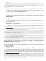
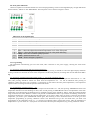
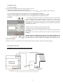
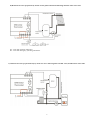
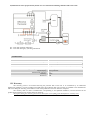
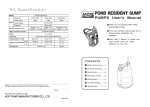
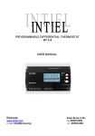
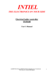
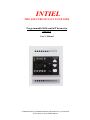
INTIEL
THE ELECTRONICS ON YOUR SIDE
Programmable Differential Thermostat
TD-3.1.1
User’s Manual
tel.:00359 596 333 66 ||| fax:00359 596 325 80 ||| info@intiel.com ||| www.intiel.com
9 Peter Beron Str, Pomorie 8200, Bulgaria
І. Application
Programmable Differential Thermostat DT-3.1.1 is used for domestic hot water preparation in water heaters, where the
heating energy is provided in combined way, by solar panels (fireplace) and electrical heating elements. It is designed to control
the circulation pump operation, installed in the water circuit between the solar panels (fireplace) and the water heater
serpentine, thus regulating the heat exchanging between them.
II. Operation
The thermostat has two temperature sensors mounted respectively in the boiler and solar panels. During an operation the
thermostat monitors the following parameters:
2.1. ∆Т, ∆t – adjusted and current (real) difference between the water heater and solar panel temperatures. ∆Т can be
adjusted in the range of 2 up to 20°С. The default setting is 10°С
2.2. Wb – adjusted temperature level of the water heater to which it can be heated from the solar panels. The
temperature can be adjusted in the range between 30 and 90°С. The default setting is 60°С.
2.3. Tbmax – maximum allowed water heater temperature. It can be adjusted in the range between 80 and 100 °С. The
default setting is 95°С.
2.4. Tpmin – minimum temperature level of the solar panel. It can be adjusted in the range between 20 and 50 °С. The
default setting is 40°С.
2.5. Tpmax – maximum allowed temperature of the solar panel. It can be adjusted in the range between 80 and 110°С.
The default setting is 105°С.
2.6. Tpdefrost – defrost temperature level of the solar panel. It can be fixed in the range between 0 up to 10°С. The
default setting is “- -“, without defrosting.
2.7. Tbmin – minimum water temperature level in the water heater. It cannot be adjusted. The default setting is 20°С
Differential Thermostat DT-3.1.1 operation depends on the temperature sensor states, as follows:
А) Normal operation
- In case of a positive temperature difference Δt between the solar panel (stove) and the water tank, greater than the set
ΔT of 3 ° C, the pump starts operation, thus heating the tank from the panel.
A timer is being switched on when ∆t gets equal to ∆T, as from this moment the controller counts 10 minutes of
circulation pump operation. That time can vary within above range of 10 minutes as decreasing the difference between ∆t and
∆T to 0 relates to less operation time of the pump, which the device count automatically. The pump operation stops if the
previous mentioned difference becomes 0 or less than 0.
- Heating the water tank under the above conditions can be made only until the temperature in the water tank gets equal
to the set one Wb, then the pump switches off, stopping the heating.
- If the above conditions are fulfilled, and the solar panel (stove) temperature falls below Tpmin, the pump stops, even
the following conditions ∆t>∆Т+3° and Тб< Wб are fulfilled.
- If the temperature of the panel falls below Tpdefrost the pump is being switched ON, although it has been switched off
because solar panel temperature is below Tpmin.
- The water tank heating by means of electrical heating elements is allowed if there are no conditions for heating
from the solar panel, the water tank temperature is 15 °C lower than the adjusted one Wb and 10 minutes have passed
since the pump has not been worked. The water tank heating by means of the the electrical heating elements is
prohibited in case of activated "vacation” mode.
В) VACATION Mode - The current mode is useful in case of not using the water tank for a long time. In case of the
mode activation the adjusted temperature is being automatically set to 40 °С, as the heating elements switching on is not
allowed. The pump is being switched on when it is necessary in order to prevent the overheating of the tank or the solar panel.
The mode can be activated by means of pressing “PROGRAM” button for 3 seconds, as after its releasing on the display
appears ON/OFF indication.
C) Emergency operation
- If during water heater warming the solar panel (stove) temperature exceeds Tpmax , the circulation pump will be
switched on by force in order to provide the solar panel cooling. The previous mentions will be done despite of the water heater
temperature can exceed Wb.
- If at the previous mentioned emergency case, the water heater temperature reaches its maximum allowed temperature
level Tbmax, the circulation pump will be stopped despite of this state can causes overheating of the solar panel. In this way the
temperature at the water heater as an overheating protection has a higher priority compare to the temperature of the solar panel
(stove).
D) Water tank and solar panel protection
When the water tank temperature Tb is above the assigned one Wb and in the same time is grater than the solar panel
temperature, in terms of preventing water tank overheating the circulation pump will be switched on. Its operation goes on
until the water tank temperature Tb is being decreased to the assigned one Wb. In this case the water tank gives the excessive
heat, as it cool itself through the solar panel. When a combine heating with electrical heating elements is being used, then the
assignation of the of the electrical part is to be a little bit lower than Wb.
2
ІIІ. Front panel indications
On the front panel are located all elements for control and programming. These are three digital display, ten light indications
and two buttons, “SELECT” and “PROGRAM”. The front panel vision is shown on Figure 1 bellow.
Fig.1
Indications on the digital display
1
2
3
4
5
6
7
8
9
10
11
Tb – shows the water heater temperature
Tp – shows solar panel temperature
∆Т – shows the adjusted temperature difference between the solar panel and the water heater
Wb – shows the water heater temperature level which has to be kept
Tbmax - shows the maximum allowed water heater temperature
Tpmin – shows the fixed minimum temperature level of the solar panel
Tpmax – shows the adjusted maximum temperature level of the solar panel
Tpdefrost – shows the adjusted temperature level for solar panel defrosting
Pump – shows the circulation pump operation
Heater - Electrical heater is ON
Alarm – shows emergency operation
IV. Programming
The Thermostat automatically goes into start mode, after connection to the power supply, showing the water heater
temperature:
4.1. Inspection of water heater and solar panel temperatures.
When the Thermostat is not in program mode, by consecutively pressing of “SELECT” button the digital display indication
is being switched over between the water heater temperature and the solar panel one, activating their relevant indications Tb or
Tp.
4.2. Inspection of temperatures mentioned at points 2.1 – 2.6 (see II. Operation, page 2.)
After pressing “PROGRAM” button the digital display will automatically show the temperature mentioned at 2.1 - ∆Т.
Then, after pressing “SELECT” button five times more the temperatures 2.2 – 2.6 will be indicated. Next pressing of
“SELECT” button will return you to position 4.1. (Inspection of water heater and solar panel temperatures). The temperature
inspection does not change the current operation of the Thermostat.
4.3. Programming of temperatures 2.1 – 2.6.
The digital display will automatically show the temperature mentioned at 2.1 - ∆Т, after pressing “PROGRAM” button. The
temperature indication will start blinking 10 times, after second pressing of “PROGRAM” button. The adjustment of the same
temperature can be done during the blinking time by repeatedly pressing of the “SELECT” button, within the possible adjusted
range. If until the 10th blink “SELECT” button is not pressed or “PROGRAM” button is pressed, the last blinking value will be
accepted as adjusted one concerning the relevant temperature. If you want to make some corrections concerning just adjusted
temperature, you need to press “PROGRAM” button again, thus returning to above mentioned actions. You can go to next
temperature programming by pressing “SELECT” button. The Thermostat will go into start mode after you finish with
programming of all temperatures from 2.1 – 2.6 and the new adjusted values will become current. After the adjustment of
temperature 2.6 you can return to 4.1 (Inspection of water heater and solar panel temperatures) by pressing “SELECT” button.
3
V. Emergency alerts
5.1. Indication Alarm
The light indication Alarm will be activated in the following cases:
- When the water heater temperature exceeds Tbmax.
- When the temperature of the solar panel is above Tpmax or bellow Tpdefros, in case a defrost mode is allowed.
5.2. The solar panel and water heater temperatures are out of preliminary fixed ranges:
- When one of the temperatures is grater than +120°C on the digital display is being indicated “Hi”.
- When one of the temperatures is lower than -20°C on the digital display is being indicated “Lo”
VI. Wiring
The wiring comprises the connection of temperature sensors, a power supply
and the circulation pump according Figure 2. The sensors are Pt1000 – non
polar. If necessary, the length of connection cables can be prolonged,
considering the total resistance of both cables, concerning indication sensibility
of 1°С/4Ω. The recommended cable length which do not affect to measurement
precision is up to 100m.
Terminals 7 and 8 are input for Pt1000 solar panel sensor.
Terminals 9 and 10 are input for Pt1000 water tank sensor
To terminals 1 and 2 are to be connected respectively phase and neutral from the
power supply.
The pump is to be connected to terminal 3 and 4, which are respectively neutral
and phase.
Caution!: In order to discharge the static electricity which could appear on
the solar panels as well their metal supports a ground connection is to be
provided. Otherwse, there is dangerous of damage concerning the sensors
even of the controller.
Terminals 5 and 6 are an independent contact which provides start/stop signal to the electrical heating elements.
VI. Hydraulic connections
А) Domestic hot water preparation only by solar panels
4
B) Domestic hot water preparation by means of solar panels and electrical heating elements of the water tank.
РТ – water tank operation thermostat
БТ – water tank emergency (blocking) thermostat.
C) Domestic hot water preparation only by means of a stove and a magnetic ON/OFF valve, installed at the water tank.
5
D) Domestic hot water preparation by means of a stove and electrical heating elements of the water tank.
РТ – water tank operation thermostat
БТ – water tank emergency (blocking) thermostat.
Technical data
Supply voltage:
Maximal rated current:
Outputs:
Switch-on difference:
Sensors:
Sensor current:
Range of temperature measuring:
Digital display:
Measurement precision:
Humidity:
Protection:
230V / АС / 50-60Hz
3А / 250V / AC / 50-60Hz
2 standard relay
ΔT 2…200С adjustable
2 temperature sensors Pt1000 (-50° до +200°C)
1 mA
from -20 up to +1200С
Three positional
1°С
0-80%
IP20
VІI. Warranty
The warranty period is 24 months following the purchase date of the unit or its installation by an authorized
Engineering Company, but not exceeding 28 months after the production date. The warranty is extended to the malfunctions
that occur during the warranty period and are result of the production reasons or defective used parts.
The warranty does not relate to malfunctions corresponding to not-qualified installation, activities directed to the
product body interference, not regular storage or transport.
The repairs during the warranty period can be done after correct filling of the manufacturer warranty card
6