1
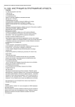
VNET LITE PC SOFTWARE MANUAL
VNET LITE PC SOFTWARE USER MANUAL
INTRODUCTION
The Art4850P stand alone or networkable proximity reader can control up to 1000 users
and the 4801 stand alone or networkable codelock can control up to 3999 users.
Additionally, 64 of these readers (Any combination of proximity or codelock) can be used
on one system, linked via an RS485 bus. The PC software enables these readers to be
programmed to allow different users different access rights for each of the 64 readers. The
software will also keep a log of user’s actions when online.
INSTALLATION
To install the program run SETUP.EXE from the root directory on the CD. After the setup
is complete, the Vprox program will appear in the start menu on your computer.
Either connect the 4850P/4801 reader to the PC using the lead provided and ensure the
reader is powered and the switch on the rear of the reader is in the RS232 position or
connect the PC via an RS232-RS485 converter (Art.VX1050) to the RS485 bus
(Remembering to terminate the 2 ends of the RS485 bus with an appropriate end of line
resistor).
When connecting the 4850P/4801 readers on the RS485 bus, each device must have a
unique ID and the 4850P which will be used for programming fobs must be ID 1 (The
reader fitted next to the PC).
To set the 4801 codelock into the VNET LITE mode, power up with the ‘ENTER’ key
pressed. To set the 4850P proximity reader into VNET LITE mode, power up with the PTE
and 0V shorted (Remove short after yellow LED flashes on the back of the unit).
To change the ID on a 4850P, power down and then power up with the STORE key
pressed. When the STORE and DELETE LED’s are illuminated, press the TEN & UNIT
keys as many times as the device ID and then press STORE to accept.
To change the ID of the 4801 keypad, follow the programming flow chart supplied with the
keypad.
COMMUNICATION PORT SETUP
Before communication can take place, the communication port and baud rate must be
selected. From the ‘Comms’ menu select ‘Baud’ and then select the correct baud rate (The
baud rate is set by the 4850P/4801 and is currently 19200). Next, choose the ‘Comms’
menu again and then select ‘CommPort’. Either choose ‘Auto Detect’ to allow the software
to find the correct communication port or select from the list of communication ports (Auto
detect will request that you select a reader to test the comms with).
START UP PAGE
To run the program, select VX4850P from the Windows Programs start menu. The screen
in figure 1 will appear.
Page 1 of 14
4850PHelp.doc Ver 2.0
VNET LITE PC SOFTWARE MANUAL
Figure 1
First choose the language be clicking on the relevant button. Then select a previously
created site file from the drop down menu. If no site file has been created then choose
‘NEW SITE’ from the drop down menu. A site file stores all the data for a given site. Up to
20 sites can be stored allowing this software to be used by an engineer who maintains
more than one site.
Existing site: After choosing the site name from the drop down menu select OK and that
site will be loaded.
New site: After choosing new site from the drop down menu an input box will appear as
shown in figure 2. Enter the new site name in this box and then press OK to create it.
Figure 2
MAIN PAGE
Figure 3
Page 2 of 14
4850PHelp.doc Ver 2.0
VNET LITE PC SOFTWARE MANUAL
The main page is shown in figure 3. The main part of the screen shows the last 20 users
that have used the system while the PC is linked to the reader via the RS232 or RS485
link. Users that have gained access are shown in green and users who have been denied
access are shown in red. Next to this there is a last user box which will display a photo of
the last user.
The lights labelled 1 – 64 along the bottom of the screen identify the status of the relay
output for each of the readers. These will illuminate green when granted access and red
when access is denied. It is also possible to double click on these lights to remotey
activate the relay.
The bar at the bottom of the screen shows the site name along with other messages used
during upload and download and also shows an upload and download progress bar.
SYSTEM SETUP
From the main page choose ‘File>System setup. The following page will appear:-
From this page it is possible to select the readers connected on the system, choose the
reader type (Proximity reader or codelock), set the relay time and select latching for the
last 100 users (4850P only) for each of the 64 possible readers. Press the ‘Save & Close’
button to exit.
Note: It is important to only select the readers connected on the system and
indicate the reader type correctly or uploading and downloading will not work
correctly.
Each of the readers can be given a suitable name from this screen. Choose the ‘NAME
READERS’ button, the following screen will appear:-
Page 3 of 14
4850PHelp.doc Ver 2.0
VNET LITE PC SOFTWARE MANUAL
Enter a name and then click ‘Close’ The reader selection page will be updated with the
new names.
ADDING USERS TO THE SYSTEM
From the File menu choose ‘User Setup’. The page shown in figure 4 will appear. To exit
this page, press the close button. The ‘ListAll’ and ‘ListUsed’ buttons toggle the table
between only showing the used locations and showing all 4000 memory locations.
Figure 4
The top of the page shows the users already stored on the system. Each user can belong
to a reader group. A reader group is a combination of readers for which this user has
access. It is possible to have up to 16 reader groups. These can be edited by pressing the
‘Create new reader group’ button (For more details see reader group section below).
Page 4 of 14
4850PHelp.doc Ver 2.0
VNET LITE PC SOFTWARE MANUAL
The ‘Edit a user box at the bottom of the screen shows the data to be edited. Here you can
add/change the users name, set/change the reader group that user belongs to, add a path
to their photo and also give them an access code which can be used on the coded
keypads on the system (Code must be from 4-8 digits).
Access codes (The 4801 keypad has 2 relays which can be triggered as follows)
Codes beginning with 0 will activate both relays together.
Codes beginning with 1 will activate relay 1
Codes beginning with 2 will activate relay 2
Codes beginning with anything else will activate relay 1
To add a new user click on the ‘Add a new User’ button. The page shown in figure 5 will
appear.
Figure 5
Select an available key number from the drop down menu or press the ‘Find’ button and
then press ok (Remember, key locations 900-999 can be setup to latch the relay on a
4850P). You will be asked if you want to store a fob (If it is only an access code you are
storing choose no). If you are programming a new fob click yes and the screen will request
that you show a fob to the reader ID1 (Red box). Once the key has been read the box will
go green and then return to the User setup screen.
On the user setup screen add the users name, the reader group they will belong to, an
access code if there are codelocks on the sysetm and if required a path to that users photo
and then press the ‘Update Database’ button. (The new user will not work until it is
uploaded to the reader at a later stage).
EDITING A USER
To edit an existing user first select that user by clicking on the relevant line on the
database table. The line will highlight as shown in figure 6. Make the changes using the
boxes at the bottom of the screen and then click ‘Update Database’.
Figure 6
Page 5 of 14
4850PHelp.doc Ver 2.0
VNET LITE PC SOFTWARE MANUAL
If the reader group is edited it will be necessary to upload to the reader before the changes
will take place. Changes to the users name and photo path do not require an upload.
DELETING A USER
To delete a user first select that user by clicking on the relevant line on the database table
(The line will highlight as shown in figure 6) and then click the ‘Delete a user’ button. The
users fob/code will continue working until an upload is carried out to the reader.
READER GROUPS
Reader groups allow a number of readers to be grouped together to simplify programming.
For example, a group of users may share access to several doors. Another group may
share access to a different group of doors. By grouping these doors together into a reader
group, it will simplify the adding and editing of users to a particular group.
Up to 16 reader groups can be selected. Reader group 1 is predefined as all readers and
reader group 2 is predefined as no readers. Reader groups 3 – 16 can be edited to be any
combination of readers.
The reader group screen can be accessed from the user setup screen. Click the button
highlighted in figure 7. The screen in figure 8 will appear.
Figure 7
To edit a group first select that group from the list. To create a new reader group, select
the ‘NEW’ button. Type in a distinctive group name and then tick the readers for which this
group will have access. Finally, click the save button to save the changes. The new reader
group will appear in the read group list and the drop down menu on the User Setup page.
The ‘Select All’ and ‘Clear All’ buttons select or clear all the readers at once. The close
button returns you to the user setup page.
Page 6 of 14
4850PHelp.doc Ver 2.0
VNET LITE PC SOFTWARE MANUAL
Figure 8
USER LOG
The user log is a database containing records of all the users who have used the system
while the reader is connected to the PC. To open this screen choose View>User Log from
the menu bar. The screen shown in figure 9 will appear.
Figure 9
For each user the following information is recorded:
• User name
• Key number
• Door number accessed
• Was access granted or denied?
• Time of access
• Date of access
Page 7 of 14
4850PHelp.doc Ver 2.0
VNET LITE PC SOFTWARE MANUAL
To the left of the screen there is a scroll bar to navigate the database.
The database has no limit to the number of records it can hold. So a DELETE facility is
also available to remove all records to prevent the database using valuable hard drive
space. To prevent unauthorised deleting of records it is necessary to enter your master
code before deleting can commence (This feature only works while connected to the
CPU).
Using the search facility it is possible to show only the records that comply with your
requirements. For example you may only want to view keys that were used on door 3 on a
particular date or view the doors that were accessed by a particular person or key number.
The search page is shown below:-
Figure 10
After completing a search, to show all records simply click on SEARCH – SHOW ALL.
If a hard copy is required click on FILE - PRINT. A standard print dialogue box will appear.
Simply choose the printer and press print.
KEY TEST
For use on proximity fob systems only
Click on the TEST A KEY option in the menu bar of the user log page. In the new window
shown in figure 11, click on the START TEST button and follow the on screen messages.
This procedure can be repeated as many times as necessary by pressing the START
TEST button. When finished simply press end to return to the previous page. Note. The
key should be presented to the reader with ID1.
Figure 11
UPLOADING DATA TO THE READER
After making changes to the user database it is necessary to upload these changes to the
reader. There are two ways to upload. The first is to upload only the changes made to the
reader by choosing the ‘Upload user changes to reader’ from the ‘Data’ menu. The second
is to upload the complete memory to the reader by choosing the ‘Upload All to reader’ from
the ‘Data’ menu. Uploading only the changes will automatically upload to all the readers on
the system whereas the upload all option will only upload to the reader you choose from
the following screen in figure 12 (Select the reader to upload to).
Page 8 of 14
4850PHelp.doc Ver 2.0
VNET LITE PC SOFTWARE MANUAL
Figure 12
UPLOAD ALL (Not necessary when uploading user changes has already taken place)
On the main page choose Data>Upload ALL to reader from the menu bar. The page in
figure 12 will appear. Select the reader to upload to by clicking on the relevant ‘SELECT’
button. The screen in figure 13 will appear requesting you to enter the master code
(Factory default is 11111111). After clicking OK the upload will commence. Warning: This
will overwrite any key already stored on the reader and not on the PC.
Figure 13
Repeat the upload to any other readers.
DOWNLOAD DATA FROM READER
If users have already been added to the reader but are not in the PC’s database it is
possible to download the reader’s contents. [Warning: This will overwrite all key data
currently stored on the PC database for that site.]. Choose the Data>Download from
reader option on the menu bar, choose the reader to download from (Figure 12) and then
type in the master code and press OK (figure 13) to begin download.
CLEAR ALL
It is possible to clear all data for a particular site and reformat the memory in the reader.
(This must be done for each reader individually on a system). This may be necessary to
free up a site database so that it can be used on another. When this process is complete it
Page 9 of 14
4850PHelp.doc Ver 2.0
VNET LITE PC SOFTWARE MANUAL
will be possible to rename the site. To use this option choose ‘Data>Clear All’ from the
menu bar on the main page and then select the reader to clear from the following page
(Figure 12). Enter the master code to begin. The data will be cleared from both the reader
and the database. Once cleared the date is not retrievable.
APPENDIX A
Installing the driver for the USB – Serial converter.
There are three routes to installing the driver on your PC. The first is for Windows 98, 2000
& XP. The second option is for Windows Vista and the third option is a manual installation
of the driver and should only be used if the other options have failed.
WINDOWS 98, 2000 & XP
Step 1: Before inserting the USB – Serial adapter, run the .exe file found on the
VX2200PC installation CD at the following address (Where d is your CD drive letter):D:\USBDriver\Windows\XP\
Step 2: After the installation process above is complete. Plug the USB – Serial adapter into
a spare USB port. If you are asked the locate the drive, choose the ‘Locate and install the
drive (Recommended)’ Option. The device should now be ready to use.
WINDOWS Vista
Step 1: Before inserting the USB – Serial adapter, run the .exe file found on the
VX2200PC installation CD at the following address (Where d is your CD drive letter):D:\USBDriver\Windows\Vista\
Step 2: After the installation process above is complete. Plug the USB – Serial adapter into
a spare USB port. The device should now be ready to use. If you are asked the locate the
drive, choose the ‘Locate and install the drive (Recommended)’ Option. The device should
now be ready to use.
MANUALLY INSTALLING THE DRIVER
Step 1: Power up and log on to the PC.
Step 2: Plug the USB – Serial converter into a spare USB port on the PC. The following
screen will appear:-
Page 10 of 14
4850PHelp.doc Ver 2.0
VNET LITE PC SOFTWARE MANUAL
Step 3: Select ‘No, not this time’ and then press Next. The following screen will appear:
Step 4: Select ‘Install from a list or specific location [Advanced]’ and then press next. The
following screen will appear:
Step 5: Un-tick the ‘Search removable media’ and tick the ‘Include this location on the
search’
Step 6: Press the ‘Browse’ button and navigate to the following location on the VX2202PC
CD:
D:\USBDriver\Windows\manual
Step 7: Follow the onscreen instructions to complete the installation.
APPENDIX B
Checking and if necessary, changing the assigned port number of your USB adapter
If you want to check if the adapter has installed correctly to a port in the range of 1 –
16 (If it has been assigned a higher number then it must be changed using the steps
below). Follow the following steps:1. From the start menu choose Control Panel (or Settings>Control panel).
2. From the new Window double click ‘System’. For Windows XP and Windows Vista
first click on ‘Classic View’
Page 11 of 14
4850PHelp.doc Ver 2.0
VNET LITE PC SOFTWARE MANUAL
3. Select the ‘Hardware’ tab and click on ‘Device Manager’ or choose Device manager
directly from the page, then expand the ‘Ports’ menu by clicking on the +
4. The USB-Serial converter will be shown in the list as ‘Prolific USB-to-Serial Comm
Port (COMx)’ Where x is the communication port number.
If the communication port number requires changing, follow these steps:(Port must be in the range of 1 – 16)
1. Click on the ‘Prolific USB – Serial Comm Port’ Line, then right click and select
‘Properties’ (Ensure the USB adapter is plugged in).
2. Select the ‘Port Settings’ tab on the new window and then click on ‘Advanced’. The
following screen will be displayed:-
3. Click on the drop down menu labelled ‘COM Port Number’ to display the list of
available communication ports.
4. Select the lowest number available (i.e. Available means it does not have ‘In use’
on that line). Click OK to accept. You must use a port number in the range of 1-16.
Remember, If the USB adapted is plugged into a different USB port or other USB
devises are plugged into the PC before this one then it may become a different COM
port number.
Page 12 of 14
4850PHelp.doc Ver 2.0
VNET LITE PC SOFTWARE MANUAL
APPENDIX C
CONNECT UP TO 64 READERS USING AN RS485 BUS CABLE.
9 Each reader must have a unique ID from 1-64 which can be programmed at the
reader using the on-board keys (Consult the reader installation manual).
9 Device 1 must be used as a programming reader next to the PC.
9 Slide switches on readers must all be towards RS485.
9 The RS485 bus must be a series link and not star wired.
9 The screen of the RS485 cable should only be connected to ground at one end.
9 The end of line jumper should be set as per the diagrams on the following page
(External end of line resistors are needed depending on overall distance).
9 A common ground is required between all readers.
9 The 1050 (Interface to the PC) can be connected anywhere on the bus and does
not need to be at the end as long as the serial link between devices is maintained.
9 A low capacitance RS485 screened cable is preferred for best performance such as
a Belden 9842 or equivalent.
Page 13 of 14
4850PHelp.doc Ver 2.0
VNET LITE PC SOFTWARE MANUAL
RS485 END OF LINE RESISTORS CONSIDERATION
The overall length of the RS485 bus will determine whether the bus termination jumpers
are closed on the two end of bus devices or whether a resistor should be fitted across the
bus A & B terminals as shown in the following three illustrations.
Up to 100 metres overall RS485 bus length.
Bus termination
OPEN
A
B
Bus termination
OPEN
A
B
Bus termination
OPEN
A
B
Bus termination
OPEN
A
B
Bus termination
OPEN
A
1000Ω
1000Ω
B
100m Max.
Up to 500 metres overall RS485 bus length.
Bus termination
OPEN
A
B
Bus termination
OPEN
A
B
Bus termination
OPEN
A
B
Bus termination
OPEN
A
B
Bus termination
OPEN
A
470Ω
470Ω
B
500m Max.
Up to 1000 metres overall RS485 bus length.
Bus termination
CLOSED
A
B
Bus termination
OPEN
A
B
Bus termination
OPEN
A
B
Bus termination
OPEN
A
B
Bus termination
CLOSED
A
1000m Max.
Page 14 of 14
4850PHelp.doc Ver 2.0
B