1
Timing data transfer
A simple technique for measuring the speed of data transmission between
microcomputers.
Undoubtedly, although fibre-optic trans
mission systems are growing rapidly in
importance, the most popular techniques
for interlinking localized computers are
still based upon the use of some form of
wire cabling. The speed of transmission
that can be achieved with cable systems
depends upon the type of cable used, the
nature of the interface circuits that are
employed and higher level factors such as
the type of software data exchange proto
cols and error checking that is performed
on the data.
We have recently been involved in the
interlinking of a variety of different
microcomputer systems1,2. The work that
has been undertaken was orientated to
wards an investigation of the use of
multiple microprocessor networks as a
means of improving the user interface with
microcomputer database systems: experi
ments designed to measure the speed of
data transmission between some of the
component computers arose as an ancillary
interest and gave rise to a simple technique
for measuring data transfer speed.
Measuring procedure
During the transmission of data between
two micros, one acts as the transmitter
while the other acts as the receiver of data.
A third microcomputer, attached to the
transmitter, can be used to measure the
duration of the data transmission transac
tion, and is referred to as the timer. The
experimental arrangement is depicted
schematically in Fig. 1 (a). Communication
between the timer and the transmitter is
via an appropriate 1 / 0 port within the
latter: if such a port is not available, a
specially designed memory-mapped in
terface can be fitted. For simplicity, the
systems to be described are all based upon
a suitable i/o port within the transmitter
and, in all cases, the ports that have been
used provide t.t.l. compatible signal levels.
Most of the experiments have involved the
use of a MOS Technology 6522 Versatile
Interface Adapter (VIA)3.
The measuring process depends upon
the transmitter changing the status of an
i/o line just before the commencement
(and just after the termination) of data
transmission - see Fig. 1(b): a program
running in the timer monitors the status of
this i/o line. When it detects the high-tolow transition it starts counting upwards
from zero, continuing until the program
su b se q u e n tly d etects th e low -to-high
transition which indicates the end of data
Department of Computer Science, Teeside
Polytechnic.
44
transfer. The value of the count contained
within the timer can then be used to com
pute the data transmission period, T ,
which may be achieved by the use of a
previously prepared calibration graph(s).
Alternatively, the known execution times
of the program instructions can be used to
calculate a loop cycle speed for the timer
prnftram, which onn thon bo uned nc a
multiplicative conversion factor.
The timer: program used in the mea
surements is shown in Table 1. It is
written in 6502 assembler code, which is
subsequently run on a Commodore PET
The alternative approach to estimating
the timer program’s loop cycle time de
pends upon a knowledge of the speed of
execution of each of its component instruc
tions. These are usually tabulated in pro
gramming manuals or hardware system
specifications6 for the 6502 chip. For the
instructions involved in the timer program
the relevant values are:
LDA
AND
BNE
INC
BNE
4 cycles
2 cycles
2 cycles
5 cycles
3 cycles
Total: 16 cycles
by Philip Barker Ph.D.
microcomputer4,5. It could easily be
converted to run on other 6502 based
systems (KIM, APPLE, AIM, etc.) by
changing the addresses of the data direc
tion register (DDR), user port (USER),
print subroutine (PRINT) and the value
assigned to the location counter at the start
of the assembly.
The program uses the PET’s 6522 VIA
pin (PAO) for its connection to the
transmitter. Zero page locations 0,1 and 2
are used to store the count value. Once the
program has been activated, it goes into a
wait state until the status of pin PAO goes
low: as soon as this happens it enters its
counting state until forced out of this when
PAO goes high again. Notice that prior to
entering the wait state the program dis
ables all interrupts (using the SEI instruc
tion) to prevent the c.p.u. being called
upon to perform any other ancillary tasks
(for example, keyboard scan, clock up
date) while the data transmission period is
being measured. Once the timing loop has
terminated, system interrupts are again
enabled (via the CLI instruction).
To test the program, an arrangement
similar to that shown in Fig. 1(c) was used.
The timer program was employed simply
to measure the length of time for which a
debounced switch circuit was held on:
after each timed interval the contents of
memory locations 0 , 1 and 2 were exa
mined and a total count value then com
puted. The results of some typical experi
ments are presented in Table 2(a). A graph
of the total loop count was then plotted
against the elapsed time as recorded by the
stopwatch, these results being shown in
Fig- 2(a). The timer program’s loop execu
tion time, as derived from the graph, is
thus 36/(22.7x 105) which is equivalent to
1.6X10- 5 seconds.
The BNE instruction can take 2, 3 or 4
cycles - depending upon whether the
branch is taken and whether the branch
operation involves crossing a page bound
ary. Since no page boundaries are crossed
the values to be used in this case are 2 and
3. A value of 2 is used for the first BNE
instruction since this branch is never taken
— at least, until the end of the interval
la) Experimental arrangement
(b) Transmitter i/o pin status
Logic high (+5V)
-------—
Start of J
transmission
T----v.End of
transmission
(c) Timer test circuit
Stop watch
Fig. 1. Measurement technique using
microcomputer as timer. Changes in status
of i/o time at (b) determine counting
period, test circuit for timer being shown at
(c). ‘
W IR EL ESS W ORLD JU NE 1983
(a) 3032 PET
Fig. 2. Graph of time against total loop
count gives loop execution time for 3000
and 8000 series PE T micros.
being timed. A value of 3 is used for the
other BNE instruction since this branch is
virtually always taken — except when
SUMH and SUMU are incremented.
The approximations used in the above
formulation for the total number of cycles
are reasonable since, if one assumes that
the microcomputer clock speed is such
that one cycles takes one microsecond,
then the loop cvcle time is easily calculated
to be 1.6x 10 seconds. This is in reason
able agreement with the value derived by
the graphical approach.
In the data transmission experiments
both a 3000 and an 8000 series PET have
been used as a timer. Converting the 3032
program (see Table 1) for operation on the
8032 computer only required changing the
address of the PR IN T routine from
$CA1 C to $BB1D. Timing experiments
analogous to those performed with the
3032 computer could then be conducted
with the 8032 system. The results are
shown in Table 2(b) and are presented
graphically in Fig. 2(b). From this graph,
the loop cycle time can be estimated as
36/(22.9 x10s), that is, 1 .6X 10-5 seconds.
This agrees closely with the value observed
for the similar program running on the
3032.
From the experiments described in this
section it is easy to see that the timer
program offers a convenient means of mea
suring data transmission speeds. It . is
limited, however, in that the smallest time
interval it could measure would be about
16 microseconds, which means that in our
experiments we could not measure trans
mission speeds faster than about 16 Mby
tes/s (PET-to-INS 8060 transfer) or 2048
Mbytes/s (P E T -to -P E T transfer).
However, because the transmission speeds
involved in our systems are well below
these limits this inherent limitation of the
timer is of little concern.
W IR ELESS W O RLD JU N E 1983
Som e data transfer
measurements
Three different examples of microcom
puter 'interconnection are described here.
Two of these involve the use of parallel
interfaces: in one case the standard IEEE488 port is used7 while in the other the
direct linking of i/o ports is employed. The
third example involves the use of a serial
interface involving the use of a one byte
buffer.
PET-to-PET transfer. The arrangement
of the equipment for this transfer opera
tion is shown schematically in Fig. 3. In
this experiment, the data lines associated
with the IEEE port of the 8032 were
directly linked to the corresponding data
lines of the IEEE port on the 3032 PET. A
third PET system, another 3032 (not
shown), was used as the timer. The
transmitter then used its PA6 output line
to interconnect with the rimrr’n PAO input
pin. Some of the other user-port lines
within the tranomitter and receiver were
employed as control lines to effect the
handshaking of the data presented on the
lines of the IEEE port. Four control lines
were used: DAV (data valid), EOT (end of
transmission), ACK (data acknowledge)
and RFD (ready for data), implemented
via user port connections PAO, PA2,
PA1/CA1, and PA3 respectively. In the
case of the ACK signal a choice between
CA1 and PA1 at the transmitter end of the
link could be used to decide whether this
was (CA1) or was not (PA1) latched.
The details of the transmitter and re
ceiver programs (in both BASIC and as
sembler) are given elsewhere1, and may be
used to send the contents of memory loca
tions $2000 through $2FFF across the data
link from PET1 to corresponding locations
within PET2. Inspection of locations 0,1
and 2 in the timer yielded the results
shown in Table 3(a). The transmission
experiment was repeated five times giving
an average count value of 26369, which
gives a transmission time for the experi
ment of 2 6 3 6 9 X 1 .6 X 1 0 "5, or 0.422
second. Since a total of 4096 bytes was
transferred during this interval, the aver
age transmission speed was therefore 9706
bytes/s.
PET-to-INS8060 (SC/MP) transfer. The
experimental arrangement for this transfer
is shown in Fig. 4. Notice that the pins
used for interfacing the INS8060 are t.t.l.compatible1 2 ,1 3 and so could be directly
connected to the appropriate user port pins
of the PET. This approach was not used
because we wished to investigate the addi
tional programming overhead associated
with using a serial-in-serial-out (siso) regis
ter as a buffer.
The way in which this interface works is
as follows. The PET uses its serial shift
register (which is a part of the 6522 VIA)
to put data (serially) into the SN74LS91
buffer. When this operation has beeri com
pleted, the PET signals ‘data valid’ to the
SC/MP through the latter’s SENSE-B in
put line. The SC/MP then generates clock
pulses (on its FLAG-0 line) and strobes the
data out of the buffer into its extension
register via its serial input pin (SIN). After
eight strobe pulses, the SC/MP acknow
ledges receipt of the data via its FLAG-1
line, which is attached to the PET’s PA 1
input pin. When the transmitter has
passed across all the data, it signals the end
of transmission by driving the EOT line
high, which causes an interrupt in the
SC/MP, causing it to jump to a special
interrupt handling routine. Notice that be
cause of the SC/MP architecture (and the
mode of operation of the PET shifjer) the
passage of a data byte from transmitter to
receiver causes bit reversal. Thus, it is
important for the transmitter to reverse the
bit pattern of all the data bytes before they
are transmitted. This is done (for all of the
data) prior to entry to the data transmis
sion loop and so the time required to do
this does not contribute to the data transfer
interval. The programs for the transmitter
(in 6502 assembler) and the receiver (ih
INS8060 assembler) are presented else
where1.
The SC/MP system used for the experi
ments had available only 256 bytes of ram
in which to store data. In view of this, only
a limited volume of data could be trans
ferred to it. The results for the transfer of
256 bytes of data from the PET (locations
$2000 through $20FF) to the SC/MP are
presented in Table 3(b): the average value
for the count is 12443 which corresponds
to a data transfer interval of 0.199 and,
since only 256 bytes were transmitted, the
average data transfer rate was thus 1286
45
bytes/s. Notice that the ratio of 9706
(parallel transfer) to 1286 (serial transfer)
is 7.55. As might be expected, byte serial
transfer is about eight times slower than
byte parallel exchange.
Z80-to-PET transfer. For these experi
ments a SOFTBOX system was used10.
This is essentially a plug-in hardware de
vice that is designed to provide the PET
microcomputer with access to the CP/M
operating system2: the control software
necessary to run the system is supplied on
a 5.25in floppy disc: a disc unit is thus
essential in order to use the SOFTBOX
interface. The way in which the unit at
taches to the PET’s IEEE bus is illustrated
schematically in Fig. 5. As can be seen
from this diagram, for these experiments,
an 8032 PET was used as a timer - inter
connection of the two PETg w q g achieved
via tlit TAO uiei pui Lline un each of (lie
machines.
W ilM i ilie 3 0 F T B 0 X is housed a Z80
microprocessor that runs at a clock speed
of 4MHz. In addition, there are 60 Kbytes
of ram and rom to store the CP/M BIOS
code2. The Z80 communicates with the
PE T ’s IEEE bus via two Intel 8255 peri
pheral support chips11, the interconnec
tions between the PET and the Z80 being
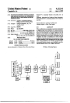
illustrated in Fig. 6 . When the Z80 system
become active, it takes over control of the
PET’s disc drive and printer (see Fig. 5).
The PET itself then acts as a dump termi
nal to the Z80 system.
In addition to storing the CP/M BIOS
code, the rom contained in the SOFTBOX
provides many other useful routines. They
may all be accessed by user programs run
ning on the Z80 memory space via a series
of jump vectors located at address $F003
and above. Two useful entry points within
the rom store are PEEK and POKE — the
POKE routine transfers data from the Z80
memory space across to that of the PET via
the IEEE bus, and PEEK is complemen
tary to POKE. This entry point can thus
be employed to move data in the reverse
direction — from the PET back to the
Z80. In both cases, the Z80 register pairs
BC, DE and H L are employed to hold the
relevant transfer parameters: B and C
specify the size of the memory image
involved, while the relevant source/target
addresses are held in D E (for the PET) and
H L (for the Z80). Details of the architec
ture of the Z80 (and Intel 8080) are given3.
A simple program for performing timed
data transfer from the-Z80 across to the
PET is depicted in Table 4.
The program is written in 8080 assem
bler. First, a 4096 byte region of memory
is initialized. Each byte within the defined
area (with base address SBDATA) is set to
the arbitrarily selected value $AB. The
POKE entries immediately following the
initialization loop then set the data direc
tion register of the PET and also put the
signal level on PAO to logic high. The call
to the dynamic debugging tool (DDT) is
then used to check that the data area has
been set up correctly; it also provides a
processing interrupt that enables the timer
program running on the 8032 to be put
into a wait state. When the program in the
Z80 is restarted it uses a series of POKE
46
commands to (a) start the timer counting,
(b) pass across the data to the PET, and
subsequently, (c) switch off the timer by
forcing the 3032’s PAO line into a high
logic state. As in the previous experiments,
processor interrupts are disabled prior to
the data transfer steps and re-enabled im
mediately after it.
The timer count values extracted from
the 8032 zero page locations (0, 1 and 2)
are presented in Table 3(c). As was the
case in the other experiments, mea
surements were repeated five times in
order to check their reproducibility, giving
an average count value of 40273. The data
transfer interval calculated from this value
is thus 0.644s which corresponds to a
transfer rate of 6360 bytes/s.
The program presented in Table 4 runs
within the environment of the CP/M dy
namic debugging package2, which was
used to take advantage of the interrupt
W IR EL ESS W O RLD JU NE 1983
T able 1. P ro g ra m fo r u sin g P E T a s tim er, co n vertib le for use w ith other 650,
m icros.
0001
0002
0003
0004
0005
0006
0007
0008
0009
0010
0011
0012
0013
0014
0015
0016
0017
0018
0019
0020
0021
0022
0023
0024
0025
0026
0027
0028
0029
0030
0031
0032
0033
0034
0035
0036
0037
0038
0039
0040
0041
0042
0043
0000
0000
0000
0000
0000
0000
0000
0000
0000
0000
0000
0000
5000
5002
5005
5007
5009
5008
500D
500E
5011
5013
5015
5016
5019
501B
501D
b01f5021
5023
5025
5027
5029
502A
502C
502E
5031
5032
5033
5035
5037
503A
503B
0043
0043
0043
0043
0043
0044
0044
0044
0044
0044
0044
0045
503C
503D
5056
5057
5058
5059
505A
505B
5070
5071
5072
5073
;TIMER
(A) 3032 PET
’
;USING PET A S A T IM E R
A9 00
8D 43 E8
A9 00
85 00
85 01
85 02
78
A D 4F E8
29 01
DO F9
EA
A D 4F E8
29 01
DO 15
E6 00
DO hb
E6 01
DO F1
E6 02
DO ED
58
A9 3B
A0 50
20 1C CA
00
58
A9 59
A0 50
20 1C CA
00
0D
OA
45 52
0D
0A
00
0D
0A
45 4E
0D
0A
00
Table 2. Results of timer calibration.
DDR=59459
USER=59471
PRINT=$CA1C
SU M L= $ 0 0 0 0
SU M H =$0001
SU M U ~$Q 002
*$5000
ST A RT LDS
#$0
DDR
;ALL PINS A S INPUT
ST A
LDA
#$0
SU M L
;ZEROISE LOW COUNT
ST A
;ZERO!SE HIGH COUNT
SU M H
ST A
SU M U
;ZEROISE ULTRA COUNT
ST A
;DISABLE INTERRUPTS
SEI
U SER
W AIT
LDA
#$01
;WAIT FOR PAO
AND
W AIT
;TO GO LOW
BNE
NOP
U SER
TIM ER
LDA
#$01
AND
END
BNE
SU M L
INC
IN C R E M E N T LOW CO UNT
TIMER
BNE
SU M H
INC
IN C R E M E N T HIGH COUNT
TIM ER
BNE
INC
SU M U
IN C R E M E N T ULTRA COUNT
TIM ER
BNE
CLI
#<ERR
LDA
#>ERR
LDY
PRINT
JSR
BRK
END
CLI
#<TUP
LDA
LDY
#>TUP
PRINT
JSR
BRK
ERR
.BYTE $D,$A, 'ERRO R - INTERVAL TOO
LONG',$D,$A,$OQ
TIME SUMU
5
10
20
30
40
SUMH
SUML
Total
Rounded
Total x 10"5
BE
AB
96
IF
04
38
19
77
A3
97
310,840
633,625
1,283,703
1,908,643
2,491,543
3.1
6.3
12.8
19.1
24.9
256
1
04
09
13
ID
26
Weight 65,536
(B) 8032 PET
TIME
SUMU
SUMH
SUML
Total
Rounded
Total x 10“5
5
10
20
30
40
05
09
13
1D
26
17
75
32
25
36
6B
64
80
79
AB
333,675
619,875
1,258,124
1,975,673
2,504,363
3.3
6.2
12.6
19.7
25.0
256
1
Weight 65,536
Tablo 3. Rocuftc of timing dntn
transfer.
A: PETTO PETTRANSFER
Expt. No,
SUMU
SUMH
SUML
1
00
00
DO
00
00
66
67
67
67
67
FE
00
00
00
00
26,366
26,368
26,368
26,368
26,368
256
1
26,369 (Av)
2
3
4
5
Weight
Total
B:PET TO SC/MP TRANSFER
Expt. No.
SUMU
SUMH
SUML
1
2
3
4
5
00
00
00
00
00
30
30
30
30
30
A1
96
9B
95
A1
256
1
Weight
Total
12,449
12,438
12,443
12,437
12,449
12,443 (Av)
C: SOFTBOX TO P E T - CASE A
TUP
.BYTE $D,$A, 'E N D OF T IM E S INTERVAL', $D,$A,
.END
Expt. No.
SUMU
SUMH
SUML
1
2
3
4
5
00
00
00
00
00
90
9D
90
90
90
5B
4F
4F
4D
51
256
1
Weight
facilities provided by the RST 7 instruc
tion. To prove that the environment pro
vided by D D T did not influence the speed
of transmission, a further experiment was
conducted. This necessitated re-writing
the transfer program in such a way that the
RST 7 calls could be dispensed with. In
stead, the same effects were achieved
through appropriate use of the CP/M
B D O S r o u t i n e s f or c ons ol e o u t p u t
(C O N O U T ) and in p u t (C O N IN ).
CONOUT was used to display a prompt
character on the 3032 screen. The Z80
processor then went into a wait loop until a
pre-defined escape character (*) was typed
on the 3032 keyboard. When the prompt
character was displayed, the 8032 timer
was started and the escape character then
typed - thereby releasing the Z80 for its
data transfer activity. The results obtained
using this approach are listed in Table
3(d). As there is no significant difference
between the results in Tables 3(c) and 3(d)
we conclude that the DDT package did
not influence the speed of execution of the
program shown in Table 4.
A f i n a l s et o f e x p e r i m e n t s was
conducted to see if the speed of transfer for
W IRELESS W O RLD JU N E 1983
PET-to-Z80 transmission was the same as
that which was observed for Z80-to-PET
transfer. To do this a new program was
written, similar to that shown in Table 4,
except that, instead of using the SOFT
BOX POKE entry, it used the PEEK rou
tine for block data transfer. The results of
this set of experiments are presented in
Table 3(e). Comparing these results with
those of Tables 3(c) and 3(d) suggests that
transfer in this direction is about 1 0 %
slower - probably due to the different
ways in which the PEEK and POKE
firmware is implemented within the
SOFTBOX unit.
It is interesting to observe that parallel
data transfer using the standard IEEE-488
bus (Z80-to-PET) is about 30% slower
than that encountered in the other parallel
transmission technique (PET-to-PET) that
was used. This discrepancy is probably
due to the additional overhead associated
with the need to specify listener/talker
addresses when transmitting data over an
IEEE bus.
The maximum speed of transmission
that can be measured using this simple
method is given by the relationship
D: SOFTBOX TO P E T - CASE B
Expt. No, SUMU
SUMH
1
2
3
4
5
00
00
00
00
00
Weight
Total
40.283
40,271
40,271
40,269
40,273
40,273 (Av)
SUML
Total
90
9D
9D
9D
9D
49
51
4A
48
61
40,265
40,273
40,266
40,267
40,289
256
1
40,272 (Av)
E: PETTO SOFTBOX
Expt. No.
SUMU
SUMH
SUML
Total
1
2
3
4
5
00
00
00
00
00
B1
B1
B1
B1
B1
C2
B2
CC
D5
BF
45,506
45,490
45,516
45,525
45,503
256
1
Weight
45,508 (Av)
S = V /1.6xl0 5 bytes/s, where V is the
volume of data (in bytes) that is passed. •
In the experiments that have been des
cribed above a fairly expensive timing ele
ment was used —far too costly to dedicate
solely for timing measurements. However,
where such machines are used as general
laboratory tools12 an approach of this type
is not unreasonable. Indeed, in the
machines used in our laboratory the timer
software shown in Table 4 is permanently
47
held in a rom module fitted to the
microcomputer’s memory-expansion sock
ets. This rom module also contains a
variety of other useful firmware that is
frequently required for other laboratory
applications; for example, terminal emula
tion, data smoothing, pattern matching
and so on.
Those situations that do not permit the
use of a general purpose laboratory
microcomputer (as described above) would
require a less costly approach — easily
achieved through the use of less expensive
single board microsystems. Indeed, we
have used a KIM micro 13 to perform
exactly the same measurements that were
undertaken by the 3032 and 8032 timer
systems - at about one seventh the cost. If
need be, further substantial cost reduc
tions for the timer system could be
achieved by simply wiring up a 6502
c.p.u.y a 6522 VIA, some rom and a simple
icAd-out system.
The autliui is giaicful to Small Systems
Engineering Ltd (UK) tor their encourag
ing help and invaluable assistance during
the preparation of this paper. He is also
Table 4. Program for timing transfer from 280 to PET.
3000 =
E84F =
E843 =
0001
=
F069 =
1000 = .
0100
0100 3E30
0102 210020
0105
0107
0108
0109
36AB
23
BC
C20501
;SO FTBO X POKE ROUTINE
;N U M BER OF BYTES TO SEN D
GENERATE TEST DATA
LO AD SO U RCE AD D R ESS
M O VE VALUE TO M EM O RY
;ALL DONE?
•INITIALISE TIM ER
010C
01 OF
0112
0115
0118
011B
011E
om
012/1
0125
010100
1143E8
215101
CD69F0
010100
114FE8
215201
CD69F0
FF
00
DPIKI:
LXI B,N1
LXI D rDDR
LXI H,DDRVAL
CALL POKE
LXI B,N1
LXI D, UPORT
LXI H.TMRSTOP
CALL POKE
RST 7
NOr
;SET PET DDR
;SET PAO HIGH
;CALL TO DDT
;PUT TIMER IN WAIT STATE
•GCNDDATATO PET M ICRO CO M PU TER .
0126
0127
012A
012D
0130
0133
0136
0139
013C
013F
0142
0145
0148
014B
014C
014D
014E
0151
0152
0153
0154
continued on page 58
Theauthor
Philip Etarkef. is _& * *i*n
. t i hi
the Deportment o l Computer Science a t
systems. The research topics in which
he is currently interested include:
author languages forcomputerassisted
;DISABLE INTERRUPTS
Dl
LXI B,1
LXI D, UPORT
LXI H,TMRGO
CALL POKE
LXI B,NSEND
LXI D, TOPET
LXI H,SBDATA
CALL POKE
LXI B,1
LXI D,UPORT
LXlH,TMRSTOP
CALL POKE
El
RST 7
BRK2:
NOP
JMP0
DDRVAL: DB 1
TM R ST O P: DB 1
TMRGO :
DB 0
END
F3
010100
114FE8
2155301
CD69F0
010010
110030
210020
CD69F0
010100
114FE8
215201
CD69F0
FB
FF
00
C30000
01
01
00
;START TIMER
;SEN D D A TA T O PET
;STO PTIM ER
;ENABLE INTERRUPTS
;CALL DDT
;W ARM START
Fig. 6. Arrangement for transferring data
between 280 in SO F T B O X and 6502 in PET.
wmmmmm
SOFTBOX.
PET
8255 p p.i.
PA
TARGET A D D R E SS FOR DATA
SO U RCE A D D R E SS OF DATA
PET USER PORT A D D R E SS
PET DATA DIRECTION REGISTER
TOPET EQU 3000H
S B D A T A EQU 2000H
UPORT EQU 59471
DDR
EQU 59459
N1
EQU 1
POKE
EQU 0F069H
N SE N D EQU 4096
ORG 100H
BEGIN
MVI A,30H
LXI H,SBDATA
FILL:
MVI M r0ABH
IN X H
CM P H
JN Z FILL
2000 =
PB
8255 p.pi.
PC
PA
PB
PC
j
6522 V.i.Q.
I
PA
PB
6520p.i,a.
PA + PB
C A hrC B
6520 p.ia.
PA^ +- CA 2
PAn
To timer.
IEEE-^88 bus:
43
C - IEEE control lines
p.p.i. - programmable peripheral interface
D - IE E E data tines
PA,PB,PC etc.-Ports A ,8,C
W IR ELESS W ORLD JU NE 1982
i aDie i . e x a m p le ot h o w the m e m o ry m a p m a y be ch a n ge d w h e n
m o re th an 1 6 K o f ram is used.
FORTH HEX
S M A X DUP @ 4000 + SW A P !
SO D U P @ 4000 + SW A P !
SP! S M A X DU P @ 4000 - SW A P !
R0 DUP @ 4000 + SW A P !
TIB DUP @ 4000 + SW A P I
' FIRST @ DU P @ 4000 + SW A P !
' LIMIT @ DUP @ 4000 + SW A P !
FIRST DUP PREV! U S E !
D P M A X DUP @ 4000 + SW A P !
D EC IM AL
( allow more data stack)
( move data stack)
( reset data stack)
( move return stack)
( move terminal input buffer)
( move Forth virtual memory buffers)
{ IE 'F IR S T 'a n d 'LIMIT')
( point virt. memory pointers to virt. memory)
{ move limit of dictionary up)
( return to decimal arithmetic)
and the counter carry being set (refresh
quantum finished), processor action is sus
pended by a dummy direct-memory-access
cycle which guarantees a non-memoryaccess cycle.
Parity checking
Capacitance used to store data in dynamic
rams is so small that naturally occurring
chargcd particlcs (alpha particles) have a
chargc great enough to corrupt data should
they hit a cell. Improved coatings on dynamic-ram dies have reduced this effect to
give an error rate below 0 . 1 %/1 0 0 0 h for
16K dynamic memories5. It is impractical
to include error correction in small 8 bit
memories but parity checking to halt the
processor when an error occurs is not.
An odd-parity bit, generated by an
LS280 parity checker when a byte is
written into memory, is stored with the
other eight bits. During the write-cycle the
parity-ram data output is in its high-impedance state and the floating EO input is
high. The parity device output is clocked
into the ram input and correct parity is
looked for when memory is read. On read
ing, the data output drives the parity
checker and the error signal is passed to
the error latch with the row-address strobe
signals. If an error exists, the RAS line
concerned is latched, a led indicates which
memory bank contains the error, and the
processor halts.
M em ory speed and drive
Input characteristics of dynamic ram are
quite different from those of t.t.l. Ram
inputs are capacitive, which especially
affects signals common to many inputs like
RAS, CAS and W E, and they require little
direct current. When driven directly from
low-power Schottky t.t.l. these inputs can
cause considerable overshoot that can re
sult in exceeding device specifications and
longer access times through the time taken
contin ued from page 48
indebted to Keith Frewin, who wrote the
SOFTBOX software, for providing roms
385 and 386.
References
1. P. G. Barker, Data Transmission Between
Micros, Electronics and Computing Monthly,
2(5), 1982,21-25 and 46-49.
2. P. G. Barker, Introducing CP/M, Electronics
and Computing Monthly, 1982, in press.
3. A. Osborne and J. Kane, An Introduction to
Microcomputers: Volume 2 - Some Real
Microprocessors, Osborne & Associates Inc,
California, 1978, Chapter 10, pp29-49.
for the voltages to level out.
To reduce ringing, some form af match
ing is required. Series matching is most
appropriate since it does not increase static
loading. The ideal driver would produce a
slightly under-damped response but be
cause t.t.l. drive characteristics are asym
metric a compromise had to be made in the
resistance value. Control signals are driven
from LS37 clock drivers to ensure ade
quate drive toward the 5V rail. Resistance
values are not critical for this relatively
slow memory and the original even worked
faultlessly with no damping resistors and
standard LS00 drive.
On analysing the timing requirement of
the ram/M6809 interface I noticed that the
most readily available 2 0 0 ns rams leave a
lot of spare time — so much so that these
devices could theoretically be run with a
6 6 6 ns cycle time instead of the standard
l^s. This was, of course, tried. N ot only
was it tried with the faster M6809A proces
sor but also with the standard device. In
both cases functioning was faultless. This
is not to say that all 1MHz parts will run at
higher speeds but certainly 2 0 0 ns access
time rams will work at 1.5MHz. So for the
cost of a new crystal the through-put of the
system was improved by 50%.
Peripherals
To ensure that IM Hz peripheral devices
such as the 6821 peripheral-interface
adapter and the 6850 communication-interface adapter operate correctly, the
memory-ready signal (MRDY) is used.
W henever p e rip h e ra ls are ad d ressed
MRDY is heljd false by an LS122 monosta
ble multivibrator which extends the
memory-access time. An M6850 commu
nication device forms the RS232 interface
and the clock frequency for it is crystal
derived. Currently the 1.5MHz c.p.u.
clock only allows I800bit/s and an external
baud generator is an attractive proposition.
Both - 5 and -r 12V supplies are used for
the RS232 interface. Current from i
-5 V supply is so low that the RS/
driver has an active current limiter; i
+ 12V drive is resistive.
Many of you will not have an RS2
terminal and will wish to use a separs
keyboard and domestic tv. The keyboa
interface will accept any 7bit parallel inp
signal with active-low most-significant-t
and active-low-going strobe and reque
signals. Two spare hand-shake lines on tl
p.i.a. and an output port could form
Centronics-type printer port.
An EF69364A video i.e. provides timir
signals necessary for a 625-line tv;
96364B device will provide signals time
for 525-line tv. Control code for the vid<
i.e. is supplied through an LS157 qua
two-to-one-line multiplexer and for norm
display characters (p.i.a. B D 7 =0) a fixe
control code is set. When control charai
ters (hexadecimal 0 to F) are used th
p.i.a. supplies the relevant code throug
the multiplexer (p.i.a. B D 7 = l) to th
EF69364. As the c.r.t. gun scans th
screen, the EF69364 selects the characte
rn be displayed from tha display rom an
latches it into an LS273.
The video i.e. was designed for use wit
ram that has separate data input and out
put lines ( 2 1 0 1 ram) so the circuit wa
modified to allow 2114 rams with commo:
i/o to be used. Character-code from LS27
and row information from 69364 i
supplied as an address to a character ron
(a specially programmed 2716 eprom)
Each character position is allocated a 7
wide-by-1 2 -high character block.
Referring to last month’s article, th
signal name at pin 6 of IC 41 is active lo'
and should read R, as should the sign;
name at the junction of IC 4 7 pin 2 and IG
pin 3. On page 57, pins 13, 12 and 5 of th
LS175 should be labelled Y0, Yi and Y
respectively.
A set of three programmed roms is aval
abl e f r o m B r i a n W o o d r o f f e at 63
Queensferry Road, Edinburgh for £23.5
inclusive. Technomatic (see advertiser:
index) will supply all i.cs mentioned in thi
article.
Disc-drive interfacing is described in th
next article.
References
5. E. Westfield, Memory system strategies fo
soft and hard errors, Wescon ’79.
1
4. Commodore Business Machines L td., CBM
PET 3032N Professional Computer User’s
Manual, Publ. No. 320856-3, June 1979.
5. Commodore Business Machines L td ., CBM
PET Series 8000 User’s Guide, Publ. N o.'
320894,1981.
6. M OS T e c h n o l o g y I n c . , M C S6 50 0
Microcomputer Family Hardware Manual,
Publ. No. 6500- 10A, 2nd Edition, January
1976.
7. E. Fisher and ,C. W. Jensen, PET and the
IEEE-488 Bus [GPIB], Osborne/McGrawHill, California, 1980.
8. National Semiconductor Corporation,
.SC/MP Technical Description, Publ. No.
4200079B, September 1976.
9. I. Williamson and R. Dale, U nderstand^
Microprocessors with the Mk 14, The Mac
millan Press, Bristol, 1980.
10. Small Systems Engineering L td., 2-4 Can
field Place, London NW6 3BT, UK
SOFTB&X User Manual, Revision 3,1981.
11. J. Kane and A. Osborne, An Introducdon tc
Microcomputers: Volume 3 - Some Rea
Support Devices, Osborne & Associates
Inc., California, 1978.
12. P. G. Barker, Computers in Analytical
Chemistry, Pergaxnon Press, Oxford, 1982.
in press.
13. MOS Technology Inc., KIM-1 Microcom
puter Module User Manual, Publ. No.
6500-15B, 2nd Edition, August 1976.
W IR ELESS W O RLD JU NE 198c