1
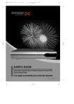
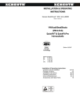
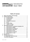
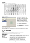
Comfort turn signal module B3
Comfort turn signal module B3
CXI - Car eXtreme International Limited
Am Fuchsberg 6
D-28870 Fischerhude
Germany
Telefon: +49 4293 91730
Fax: +49 4293 917333
www.cxi-europe.com
This manual is to be handed out to the future owner and should
always be carried in the car.
diagramm in principle
_______________________________________________________________________________
Comfort turn signal module B3MOS-FET and B3PLUS
Installation and user manual
Characteristics
The comfort turn signal B3 recognises the brief press on the turn signal switch and will
automatically flash the relevant turn signal three times. The switch does not need to be held
or pressed fully. This increases safety and comfort while switching from one lane to another
and is already factory installed in many modern vehicles. The B3 provides you with the
equipment to retrofit this additional safety feature in older vehicles.
extendet diagramm of connections
Simple installation, only five wires to connect
Cars wires do not have to be cut
Small dimensions enable it to be hidden in each vehicle
Adjustable from three to fife flashes
All functions are controlled by a microprocessor
Optimized tapping intervals increases the convenient operation
Safety functions recognize potential errors in the turn signal system
Modern efficient MOS FET amplifiers enable silent operation
The unit is suitable for normal turn signal systems with a fuse up to 15 Amps. During the
development we have paid particular attention to security and safety. The parallel connection
construction (involving no cut wires) enables a simple installation and leaves the cars turn
signal system untouched. Therefore the B3 can be uninstalled without trace. At the time of
printing, the equipment does not have a general operating permit and users are advised to
check National rights.
B3V17E.050321
copyright 2005 CXI Ltd., all rights reserved
•
•
•
•
•
•
•
•
1
Comfort turn signal module B3
Comfort turn signal module B3
Note
Please thoroughly read this manual before attempting installation, paying particular attention
to the above safety references and the disclosure of non-liability herein.
Operation
Normal signalling, (fully engaging the turn signal stalk), is not affected by the B3. The B3 only
controls signalling when the stalk is touched lightly and flashes the turn signals automatically
three times in the desired direction.
The automatic flashing can be cancelled at any time by pressing the stalk in the opposite
direction. This interrupts the flashing immediately. The nature of the subsequent press
decides whether the B3 will activate the other turn signal or not.
1. Disassembling the emergency switch,
plug with pin numbers.
2. Carefully release the harness
from its foam surround.
3. Inserting the wire into the clamp,
check the connections.
4. Completed connections,
fife splice clamps.
A courtesy “Thank You” after overtaking is also possible. If, for example, you want to flash
once left and once right, the switch must be held a little longer when right flashing.
If you feel flashing the turn signal three times is not sufficient, you can adjust the B3 to flash four
or even five times. See section 4. Adjusting the flashing time of the Installation guide.
Sometimes the B3 will not flash three times as expected. This is because of the overload
recognition system. If the B3 tapping function is used more than 20 times over a short period
of time, a temporary deactivation takes place. After waiting a few seconds the B3 is ready
again. This function protects the electronics and all adjacent vehicle parts against any
damage that may be caused by the B3 heating up.
What you receive
• B3MOS-FET comfort turn signal module or B3PLUS comfort turn signal module
• Wiring harness with plug and splice clamps
• These instruction (The B3PLUS comes with an additional addendum)
2
5. Mounting the module.
Fasten the module if possible
with a strip insulating tape to
the wiring harness. Make surethat
it would not attached too tightly
Comfort turn signal module B3
Comfort turn signal module B3
Remove the emergency/hazard light switch and take off the rear plug. If necessary remove a
few inches of the foam surround to give you enough free wire to attach the splice clamps.
Find your car in the table below. Mark the line with your vehicle in the column My Car and
connect the five wires of the module with the respective wires of the emergency/hazard light
switch. Be sure to use the contact numbers on the plug and not rely on the colours, because the
wire colours are often duplicated or very hard to recognize.
Vehicle
My
Car
B3 wire colour
blue
yellow
black
red
Audi A3 ...98
5
6
1
3
2
Audi A3 99...04
9
2
3
5
7
Audi A4 ...01
5
6
1
3
2
Audi A6 ...04
9
2
3
5
7
Audi A8 ...97
4
3
7
5
6
Audi A8 98...03
9
2
BR-8
5
7
Audi RS6 ...05
9
2
3
5
7
Audi TT
9
2
3
5
7
Opel Astra ...97
2
9
1
4
7
Skoda Octavia
6
7
1
3
2
VW Golf4/Bora
6
7
1
3
2
VW Passat
5
6
1
3
2
VW T4
6
7
1
3
2
More cars can be found at www.cxi-europe.com
10
white
Guidance and Safety Notes
The following information is particularly important and you are advised to ensure you fully
understand it.
• Before attempting installation of the B3 carefully read these guidance notes.
• Although the equipment has been constructed and manufactured to high safety standards,
you are advised to handle it with care.
• The equipment may only be operated with the provided accessories. No alterations must be
made.
• During installation, ensure the battery is disconnected and that the key is not in the ignition.
• Pay particular attention to the polarity of the B3. Incorrectly wiring the B3 will destroy the
equipment.
• Monitor the B3 for any signs of defects. Prolonged incorrect functioning can lead to damage.
• Do not mechanically load the B3 module (e.g. get jammed).
• Use only with 12 V electrical systems.
• Use only on turn signals with a maximum of 15 A fuse.
• Ensure the module is securely mounted.
• Do not open the module housing. No user serviceable parts are inside.
• Do not install in areas susceptible to extreme temperatures or dampness. The module is not
suitable for installation in the engine compartment.
• Install the equipment behind the vehicle’s fascia, so that it cannot cause injuries in the case
of an impact.
• Ensure that after installation the equipment switches off when you remove the ignition key.
• Pay attention to other road users at all times and do not let the equipment impede your
driving.
• Legal guidelines are to be followed at all times. These differ from country to country.
Incorrect installation may lead to damages to the equipment, to the car or to persons (see
non-liability). Therefore we strongly recommended a qualified engineer carry out the
installation.
BR = extra turn signal relay
3
Comfort turn signal module B3
Conditions
Comfort turn signal module B3
Appendix
The B3MOS-FET module can only be operated with conventional turn signal systems. These are
systems in which the current is lead from the fuse to the turn signal relay, directly to the turn
signal switch and then to the bulbs.
1. LED control light and the meanings of the signals.
LED status signal
meaning
The B3PLUS comfort flashing module can be operated by turn signals, in which the current first
goes to the switch and then to the flashing relay to the bulbs.
lights 1x briefly
Ready status after switching on,
stored characteristics are used.
Turn signal systems, in which the turn signal switch is attached at a controller but has no
connection to the bulbs, cannot be retrofitted with B3MOS-FET or B3PLUS. In these cases please
use the B3TTL for digital turn signal systems.
lights 2x briefly
Ready status after switching on,
learning mode is active (very short tapping).
shines brightly
Tapping recognized, flashes 3x
shines weakly
After tapping the module momentarily pause
for approx. half a second
fast continuous
flashing
temporarily deactivated,
overload recognition, cooling phase
short lightning
thermal load has dissipated
3 short flaches
RESET, stored characteristics deleted
fast flashing
with short breaks
permanently deactivated,
Failure with the turn signals, e.g. a bulb isdefective
lomg shining,
no bulbs are flashing
Failure or incomtatibility, e.g. flashing relay is defective
(ends with permanently deactivation, see above)
Installation
1. Preparation
Installation using the enclosed splice clamps is quite simple, but nevertheless should only be
carried out by a specialist. Knowledge of the cars electrical system is necessary to connect
the five wires of the B3 module.
In the appendix you will find the wiring diagram for the B3MOS-FET. For the B3PLUS please use
the additional diagram (found in the addendum). If the flashing relay is part of the emergency/
hazard light switch, it is recommended you connect the module there as you will find all
necessary connecting points (see extended diagram of connections). In this case please
ensure all wires are of the same length. You will find a table for different models from the
VAG Company in the appendix.
NOTE: Before undertaking any work on the electrical equipment of the vehicle please
disconnect the battery. If necessary, ensure you have all codes needed to unlock
protected devices such as radios, navigation systems or cellular phones.
The above signals do not need to be monitored during normal operation. They only become
important in cases of maintenance and as such the module can be mounted out of site.
2. Connection points in some cars (without guarantee)
It is recommend to connect the module to the harness off the emergency/hazard light switch, if
this also contains the flashing relay. This is the case with the cars in the following table.
4
9
Comfort turn signal module B3
Comfort turn signal module B3
2. Connecting the harness
Registered trade mark
Copyright 2004, 2005 CXI - Car eXtreme International Limited. All rights reserved.
All the product names mentioned in this manual can be brands and/or registered brands of the
respective enterprises.
Statement of Non-Liability
All products manufactuered or sold by CXI are designed/intended for off-road use. If, while
attempting to apply any of the ideas, procedures, product recommendations, suggestions or
products purchased from CXI’s site or contained on this web site you should experience a
failure of any kind, it will be the result of your own conscious decision. CXI disclaims all
responsibility for your failure except replacement of items purchased from CXI, if covered under
manufactuer warranty.
The power consumption of the module in standby mode is very small. However do not
connect it to a constant live source, but - like the turn signals - with the ignition switched on.
First disconnect the negative terminal of the battery. Use the enclosed blue splice clamps for
all connections, unless otherwise instructed. The clamps have one one-sided and one
double-side cable run. The cables of the module are inserted into the one-sided chamber, the
chamber is locked by closing the cover and squeezing with flat-nosed pliers until the hook
engages. Ensure the cable insulation is broken and that the wire comes in contact with the
metal of the clamp. The cars cables are inserted into the double-side chamber and are
installed in the same manner.
The red splice clamps are intended for use on cables with a small diameter, the blue splice
clamps for those with larger diameters. First connect the black cable of the module to
ground (minus mass) and the red to switched positive (only when ignition is on). If the cars
wiring (usually only the ground wire) is particularly thin, please use a red clamp. Make sure
that the positive connection you use is fused. When installing at the emergency light switch
the fuse of the turn signal system is used.
As you will have noticed, the module has five pins. Initially you must only connect the positive and negative, do not connect any other wires. You must now test, by watching the LED,
whether the connections you made are working.
If the LED does not flash it may be for one of two reasons: a) the module is incorrectly
connected or b) it is connected to a non-switched positive (a constant live source). In the
case of b) ask a second person to disconnect and connect again the battery. If the LED
flashes you have incorrectly connected it to a constant live source.
If the LED does not flash at all, there is probably a problem with the contacts. Disconnect the
negative battery terminal again and swap the two blue splice clamps for red clamps, (suitable
for smaller cable diameters) ensuring you work carefully, to prevent any damage to the cars
wiring.
If the LED flashes when you turning the ignition key, the connection is perfect. You can now
attach the remaining wires using the blue splice clamps ensuring you have first disconnected
the battery.
8
5
Comfort turn signal module B3
Comfort turn signal module B3
3. Start-up + function test
5. RESET + Lerning mode
At this time the module should not be installed behind the fascia to enable you to observe the
status signals of the LED. You will find a table with the different status signals and their
meaning in the appendix.
After maintenance work (e.g. replacement of the turn signal relay) and to adjust the flashing
time it is necessary to reset and retrain the module. For this you must follow the RESET
procedure (to delete the module’s memory) and activate the learning mode.
Attach the battery again and switch on the ignition. The LED will flash once or twice. If it
flashes twice, the module is already in learning mode. If the LED flashes once you should
RESET the module (described in section 5.), to force it into learning mode. Once you have
done that carry on with the following.
In order to prevent an inadvertently initiated RESET, the RESET procedure can only be done
a short time after switching on the ignition. Please proceed as follows:
Briefly flash (tap turn signal switch) once to the left or right. The turn signal will automatically
flash three times and the turn signal systems characteristics will be determined and stored.
The learning mode is finished.
4. Adjusting flashing time
During normal operation the module will flash three times. If you wish it to flash more, the B3
can be changed to four or five flashes. To change it, please proceed as follows:
a)
b)
c)
d)
Do a RESET as described in section 5., to force the module into learning mode. Once
done, carry on with the following.
Hold the turn signal switch to the left and count your desired number of flashes, three
four or five.
Hold the turn signal switch to the right and count your desired number of flashes.
Tap the turn signal switch very briefly in any direction to store the value. The vehicle will
flash three, four or five times according to the stored value, to confirm your chosen amount.
a)
b)
c)
Switch off ignition.
Switch on ignition and wait for approx. 5 seconds.
Switch on the emergency light switch and off again.
If the emergency light will be switched on too early or to late, the RESET will be prevented. The
same occures, if you flash to the left or right.
To confirm the RESET was accomplished the LED briefly flashes three times (if the
properties were not already deleted). The module is now in learning mode and you can
continue with the start-up procedure or adjust the flashing time.
6. Final work
The comfort turn signal B3 can be fitted anywhere behind the fascia, but not in the engines
compartment. Because it radiates some heat, you should not tape it onto any flammable
material. Simply fix the module with some insulation tape to the wiring harness. Avoid areas
of high dampness and temperature (i.e. heating system, condensation, or air-conditioning
system).
You must follow the above sequence precisely. This is the only way to change the desired
number of flashes. If you want to change the value, repeat the procedure again, beginning
with a).
Note: The RESET does not change the stored value back to three flashes. The value remains
until it is replaced with another, as described above.
6
7