1
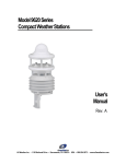
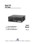
20980-A RADIO
MODEM
USER'S MANUAL
All Weather Inc. • 1165 National Drive • Sacramento, CA 95834 • 800.824.5873 • www.allweatherinc.com
User's Manual
Model 20980-A Radio Modem
Contents
INTRODUCTION
1
Serial Port ........................................................................................................................1
Programming ...................................................................................................... 1
PHYSICAL CONNECTIONS
1
Antenna Connector......................................................................................................1
Power Connector ..........................................................................................................1
Serial Port Connector....................................................................................................3
LEDs..................................................................................................................................3
LICENSING AND INSTALLATION
4
Licensing .........................................................................................................................4
Installation ......................................................................................................................4
AWOS DCP Installation ....................................................................................... 4
AWOS CDP Installation ....................................................................................... 4
RADIO MODEM ALIGNMENT
4
AWOS PERIODIC MAINTENANCE
5
Monthly Maintenance ..................................................................................................5
CDP ...................................................................................................................... 5
DCP (Tower)......................................................................................................... 5
Quarterly Maintenance................................................................................................5
CDP ...................................................................................................................... 5
DCP (Tower)......................................................................................................... 5
Annual Maintenance....................................................................................................5
CDP ...................................................................................................................... 5
Power Level ........................................................................................................6
VSWR (at transmitter) ........................................................................................6
Frequency ..........................................................................................................6
Deviation ............................................................................................................7
DCP (Tower)......................................................................................................... 7
Page i
User's Manual
1.0
Model 20980-A Radio Modem
INTRODUCTION
The 20980-A is an integrated modem and radio that provides digital data transmission at data rates
greater than 19,200 baud (bits per second). Versions are available that operate in both the VHF and
UHF frequency bands. The 20980-A is a half duplex unit, meaning that it can receive or transmit,
but cannot do both simultaneously. However, two units can be combined to provide full duplex
capability. The electrical specifications of the 20980-A are shown in Table 1.
The user data interface is a serial port through a 9-pin D connector, and can be configured for either
RS-232 or TTL signal levels. The data format is asynchronous with either 8 or 9 data bits. The
modem can operate with either the standard DTE/DCE handshake signals or in data activation
mode which requires only the receive and transmit data lines.
2.0
MODEM SETUP AND OPERATION
2.1 Serial Port
This user interface utilizes a female 9 pin D connector. This is the same serial connector used on
many PC AT type computers, except that the computers use a male connector. The modem serial
port operates in ADATA activation mode (no handshaking required).
The data activation protocol requires the use of only the transmit data (TD) and receive data (RD)
lines. When activity is detected on the transmit data line, the transmitter is keyed. The transmitter
will remain keyed until there is no activity on the transmit data line for at least 10 character periods.
2.2 Programming
Radios are programmed to customer-specified requirements at All Weather Inc.
3.0
PHYSICAL CONNECTIONS
3.1 Antenna Connector
The antenna interface to the 20980-A is through a standard 50 ohm female BNC connector. The
modem should never be allowed to transmit without connecting either an antenna or dummy load to
this connector. A variety of antennas can be used with the 20980-A, but it is important that the
antenna used provides a 50 ohm load at the operational frequencies. Any cabling used to remote the
antenna must be good quality coaxial cable with 50 ohm characteristic impedance. Depending on the
license obtained for operation, there may be restrictions on the type and height of the antenna which
may be used.
3.2 Power Connector
Power can be fed into the modem either through the Molex connector on the front of the modem or
through pin 9 of the serial port (see figure 1). The power into the modem should be a well regulated
DC voltage between 9 and 16 volts. The power pin of the Molex and pin 9 of the serial port are
directly connected. In most applications, pin 9 of the serial port is either unused (unconnected) or is
a ring indicator which is a modem output. For systems operating on RS-232 levels, the power
feeding to this pin is in the normal RS-232 voltage range and should not present a problem. For
other systems, it may be necessary to leave pin 9 of the serial port unconnected.
Page 1
Model 20980-A Radio Modem
User's Manual
TABLE 1
20980-A RADIO MODEM
ELECTRICAL SPECIFICATIONS
Data Interface
Data Rates
Data Format
Signal Levels
Handshake Protocols
Data Only Time Out
Data Connector
300, 1200, 2400, 4800, 9600, 19200, 38400 baud
Asynchronous; Word length: 7 or 8 bits;
Parity: Even, Odd, or None
RS-232, TTL (Port 1 only)
Full Handshake: Supports RTS, CTS, DCD, DSR, DTR; Data
Activation (3 wire): Requires only TXD, RXD, and SG
1 to 500 character periods
9-pin D, female, DCE (std. case)
Radio – General
Frequency Range
Channel Step Size
Frequency Stability
FCC ID
FCC Authorizations
IC (Industry Canada) ID
IC Authorizations
RF Connector
450-470 MHz
6.25, 10 kHz
±1.5 ppm
JWFTS4000A (403-512 MHz)
11K2F1D, 16K0F1D, 20K0F1D
3163195426 (403-512 MHz)
11K2F1D, 16K0F1D, 20K0F1D
BNC, female, 50 W (std. case)
Radio – Transmitter
Transmit Power
Duty Cycle
Attack Time
0.1 to 2 watts (programmable)
50% @2 watts, 100% @0.2 watts and below
20 ms
Radio – Receiver
Receive Data Sensitivity/
BER (Bit Error Rate)
Carrier Detect Threshold
Receive Filter Bandwidth
Selectivity
Spurious/Image Rejection
Intermodulation
-103 dBm for less than 1x10⁻⁴ BER
-110 to -60 dBm (programmable)
12.5, 25 kHz
-60 dB (12.5 kHz); -70 dB (25 kHz)
-70 dB
-70 dB
General
Supply Voltage
Power
Power Connector
Data Buffer
Program Storage
LED Indicators
Operating Temperature
Dimensions
Weight
Page 2
9-28 VDC (full transmit power)
1.0 watts - Standby (typical)
1.5 watts - Receive (typical)
7.0 watts - Transmit (typical)
2-pin Molex or through serial port
32 kByte SRAM
512 kByte Flash ROM (supports in-field firmware upgrades)
Transmit, Receive, Power (see section 3.4)
-22 to +140° F (-30 to +60° C)
4.3" x 3.1" x 1.8" (109 mm x 79 mm x 46 mm)
12 ounces (340 g)
User's Manual
Model 20980-A Radio Modem
3.3 Serial Port Connector
The serial port connector is a female 9 pin D connector. The cable used to connect to the serial port
should be good quality shielded cable with metal connectors. The cable connectors should be
securely screwed to the modem’s serial port.
3.4 LEDs
The Model 20980-A has three LED indicators to provide operational status of transmit (TX), receive
(RX), and power (PWR) functions. Special combinations of these indicators are used to indicate
secondary operating modes and fault conditions.
20980-A State
LEDs
Indicator State
Normal Operation
PWR
RX
TX
On when the 200980-A is powered
On when the 20980-A detects activity on the radio
channel
On when the 20980-A is transmitting
Program Mode
RX, TX
Both on continuously
Reset
RX, TX
Flash together four times
Although the reset indication takes about
four seconds to complete, the 20980-A is
fully operational when the flashing begins.
Transmit Test Mode
TX
Flashes for the duration of the test
Invalid Frequency
Channel Fault
RX, TX
Alternately flash
This fault occurs if the 20980-A is set for a
channel that does not have a valid
frequency programmed.
Transmit Buffer Overflow
TX
Flashes ten times for each occurrence
Receive Buffer Overflow
RX
Flashes ten times for each occurrence
Diagnostics Fault
PWR
Flashes for the duration of the fault
In this mode the 20980-A has detected a
fault but continues to operate. Operation
may be unreliable due to the fault.
The most common cause of this state is an
out-of-range power source. the source of the
fault can be diagnosed with the configuration
program.
Catastrophic Fault
RX, TX
Alternately flash until the fault is cleared and the
20980-A is reset
In this mode the 20980-A has detected a
catastrophic fault and is non-operational
until the fault is corrected.
The source of the fault can be diagnosed
with the configuration program.
Page 3
Model 20980-A Radio Modem
User's Manual
4.0 LICENSING AND INSTALLATION
4.1 Licensing
The 20980-A operates on frequencies which are regulated by the Federal Communications
Commission (FCC). Therefore, it is necessary to obtain a license before this equipment is operated
on the air. In general this is not a difficult process, and All Weather Inc. can aid with any issues or
questions relating to licensing.
The 20980-A has been tested and found to comply with the limits for a Class B digital device,
pursuant to Part 15 of the FCC rules (Code of Federal Regulations 47CFR Part 15). Operation is
subject to the condition that this device does not cause harmful interference.
The 20980-A has been type accepted for operation by the FCC in accordance with Part 90 of the
FCC rules (47CFR Part 90). See the label on the unit for the specific FCC ID and any other
certification designations.
the 20980-A has bee type accepted for operation by the FCC in accordance with Part 101 of the
FCC rules (47CFR Part 101). See the label on the unit for the specific FCC ID and any other
certification designations.
Any changes or modifications to this equipment not expressly approved by All Weather Inc. could
void the user’s authority to operate this equipment (FCC rules, 47CFR Part 15.21).
4.2 Installation
To ensure proper and satisfactory operation, the 20980-A should only be installed by qualified
professionals.
4.2.1 AWOS DCP Installation
Attaches to the DCP Sensor Interface board. Refer to the Model 1190 DCP User's Manual for
installation instructions.
4.2.2 AWOS CDP Installation
Refer to the Model 2090 CDP User's Manual for installation instructions.
5.0 RADIO MODEM ALIGNMENT
The 20980-A should be aligned and serviced only by certified technicians. Making internal
adjustments can cause incorrect operation, illegal emissions, damage to the unit, and can also void
the manufacturer’s warranty.
The 20980-A radio modem is aligned and tested at All Weather Inc. prior to shipment. Each 20980A Radio Modem shipped from the factory is configured for the following operation:
Baud Rate
9600
Character Length:
8 bits
Serial Configuration:
Enhanced
Data Scrambling:
On
Handshake Protocol:
Data Activation
Time Out Timer:
Off
Serial Data Signal Level:
RS-232
Page 4
User's Manual
Model 20980-A Radio Modem
Synthesized 20980-A Radio Modems are shipped with channel 1 programmed to the site specific
receive and transmit frequency.
6.0 AWOS PERIODIC MAINTENANCE
When this instrument is installed in an AWOS system, periodic maintenance and verification must
be carried out according to a schedule that includes monthly, quarterly, and annual procedures.
6.1 Monthly Maintenance
6.1.1 CDP
• Inspect the antenna and cables for damage. Repair or replace damaged components.
• Select the DCP status display screen from the Maintenance Menu, and verify that the
displayed ratio of CRC errors to properly received data packets is less than 10%.
• If the ratio of errors to good data is greater than 10%, adjust the antenna position and verify
there are no obstructions between the sensor tower and the receiving antenna. If the problem
persists, replace the radio.
• On the DCP status display screen, verify that the timeout error percentage is less than 5%.
• If the timeout error percentage is greater than 5% but some data is being received properly,
adjust the antenna position and verify there are no obstructions between the sensor tower
and the receiving antenna. If the problem persists, replace the radio.
• If the timeout error percentage is greater than 5% and no data is being received, verify that
the CDP radio is powered and that the interface cables are connected properly to the PC. If
no problem is found, verify that the sensor tower radio is powered and connected properly.
If no problem is found, replace both the CDP and DCP (sensor tower) radios.
6.1.2 DCP (Tower)
• Inspect the antenna and cables for damage. Repair or replace damaged components.
• Inspect the radio. Verify that the Transmit and Receive LEDs flash at 5-second intervals.
• Select the date and time screen on the DCP keypad. Verify that the date and time are correct
and that the time updates at 5-second intervals.
• If the time is updated less frequently (e.g., every 15-30 seconds or longer) adjust the antenna
position and verify there are no obstructions between the tower and the transmitting
antenna (located near the CDP). If the problem persists, replace the radio.
6.2 Quarterly Maintenance
6.2.1 CDP
For quarterly maintenance, perform the monthly maintenance procedures described above.
6.2.2 DCP (Tower)
For quarterly maintenance, perform the monthly maintenance procedures described above.
6.3 Annual Maintenance
6.3.1 CDP
Annual maintenance and validation of the Model 20980-A UHF Radio located at the CDP consists
of the following tests:
•
•
•
Power level
VSWR (at the transmitter)
Frequency
Page 5
Model 20980-A Radio Modem
•
User's Manual
Deviation
6.3.1.1 Power Level
1 Remove power from the UHF radio by disconnecting the DB9 connector.
2 Connect a power meter between the connector on the radio and the cable to the antenna.
3 Place the 2.5 watt 400-850 MHz frequency element in the power meter. The element arrow
shall point to the antenna.
4 Reconnect the DB9 connector to restore power to the UHF radio. Measure the forward
power on the power meter. This should be approximately 1W. Enter the value on the data
sheet.
6.3.1.2 VSWR (at transmitter)
1 Replace the power element with a 1 watt 275-450 MHz frequency element with the arrow in
the direction of the radio. NOTE: Damage will occur to the element if the arrow is in the
direction of the antenna.
2 Measure the reflected power. Enter the value on the data sheet.
3 Calculate the VSWR from Figure 1 and enter the value on the data sheet.
1+
reflected power
forward power
1−
reflected power
forward power
VSWR =
Sample calculation:
reflected power = .02 W
forward power = 5 W
reflected power
forward power
.02
1 + .004 1 + .063 1.063
5
=
VSWR =
=
=
=
= 1.134 VSWR
reflected power
.02 1 − .004 1 − .063 .937
1−
1−
5
forward power
1+
1+
Figure 1 VSWR Calculation
6.3.1.3 Frequency
1 Replace the power element with the RF sampler element.
2 Connect an RG-58 coaxial cable from the sampler to the frequency meter.
3 Set the frequency meter to "500" MHz range, "fast" gate, and "batt" power.
4 Measure and log the frequency on the data sheet.
Page 6
User's Manual
Model 20980-A Radio Modem
6.3.1.4 Deviation
1 Replace the frequency meter with the deviation meter.
2 Connect the coaxial cable to the RF input on the meter. Set the meter switches to:
Function
Range
Filter
De-emphasis
Power
3
FM +
10 KHz
25-15 KHz
Off
On
Enter the meter reading on the data sheet.
6.3.2 DCP (Tower)
Repeat the annual maintenance procedures described above for the CDP on the radio installed at the
DCP (tower site).
Page 7
All Weather Inc.
1165 National Drive
Sacramento, CA 95834
Fax: 916.928.1165
Phone: 916.928.1000
Toll Free: 800.824.5873
www.allweatherinc.com
20980-A01
Revision B
ECO 1077