Download TG-10STX _Manual


Transcript
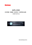
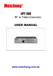
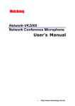
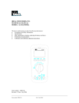
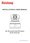
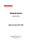
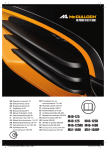
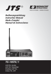
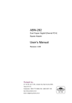
Meicheng ®
IN-EAR Monitor Stationary Transmitter Receiver System
TG-10STX / TG-10SRX / e-8TH / UDA-49P
Stationary Transmitter / Stationary Receiver
UHF PLL Handheld Transmitter / Passive UHF Directional Antenna
USER MANUAL
www.meicheng.com.tw
TG-10STX Stationary Transmitter
1. Important Cautions………………………………………………………………………………1
2. Introduction…………………………………………………………………………………………1
3. Specification……………………………………………………………………………………… 1
4. Parts Identification & Accessories…………………………………………………………2
5. Preparing procedures & basic operation…………………………………………………3
6. Loop Out Application ………………………………………………………………………… 5
TG-10SRX Stationary Transmitter
1. Important Cautions………………………………………………………………………………6
2. Features………………………………………………………………………………………………6
3. Specification………………………………………………………………………………………7
4. Parts Identification & Accessories…………………………………………………………7
5. Preparing procedures & basic operation……………………………………………… 8
e-8TH UHF PLL Handheld Transmitter……………………………………………
10
UDA-49P Passive UHF Directional Antenna……………………………………11
TG-10STX Stationary Transmitter :
1. Important Cautions:
.Make all connections before plugging the unit into an AC power outlet.
.Do not leave the devices in a place with high temperature or high humility.
.Do not handle the power cord with wet hands.
.Keep the devices away from fire and heat sources.
2. Introduction:
.The TG-10STX is an UHF PLL stationary transmitter with 16 selectable channels.
It works with all 16 channel systems with channel indication 0,1 ,2 ....9 , A , B... , F.
.Together with directional antenna UDA-49P, the TG-10STX can provide stronger
signal for larger coverage.
3. Specification:
.Carrier Frequency Range: 502~960MHz
.RF Output Power: 10mW
.Nominal Frequency Deviation (modulation): ±40KHz
.Audio Input Impedance: 20KΩ
.Maximal Input Level: -20 dBV
.Nominal Input Level: 0 dBV
.LED Display: AF Level, Channel
.Audio Input Connector: 2 x Balanced XLR / Ø6.3mm Combo input
1 x Ø6.3mm monitor input
.Input Monitor Connector: 1 x Ø3.5mm phone jack
.Loop Out Connector: 2 x Ø6.3mm Balanced Loop Out phone jack
.Operation Voltage: 12-18 VDC, 600 mA
.Dimension (m/m): 210 (W)* 44 (H)* 239 (D)
.Channel: 16 selectable channels
-1-
4. Parts Identification & Accessories:
1. Power On/Off switch
2. LED Display
3. Channel Selector (“+” button)
4. Set button
5. Channel Selector (“–” button)
6. Volume control (For CH1&CH2)
7. Monitor volume/channel control
8. Ø3.5mm Stereo Phone Jack
9. Antenna
10. DC input (12~18V 600mA)
11. Balanced Loop out Connector CH1
12. Balanced Loop out Connector CH2
13. Balanced XLR/ Ø6.3mm Combo
Input Left (support phantom power by adjusting 17. to “on”)
14. Balanced XLR/Ø6.3mm Combo
Input Right / CH2
15. BNC Antenna Output Socket
16. Monitor input (mono Ø6.3mm phone jack)
17. CH1 phantom power switch
Optional Accessory
18. RM-901 Rack Mount Kit
19. RTF-1 Antenna Extension Cable
-2-
5. Preparing procedures & basic operation:
(1) Connect the main unit:
Connect the DC INPUT in the rear panel of TG-10STX to an AC to DC adaptor.
(2) Basic operation:
1. Connect the mixer output to the XLR / Ø6.3mm combo CH1 input at the rear panel of
TG-10STX with AF input cable. (Support phantom power)
2. Connect the gooseneck mic (PA-100) and gooseneck mic base at the XLR /
Ø6.3mm combo CH2 input at the rear panel of TG-10STX with AF input cable.
3. Connect the HS-9100 or TG-10SRX at the Ø6.3mm mono CH3 input at the rear panel of
TG-10STX with AF cable as a source for interpretation.
[NOTE]:
1. Two balanced XLR / Ø6.3mm combo inputs are provided. You may use either
one input or both for a stereo source. Also, two balanced Ø6.3mm loop out connector
are provided for multiple systems application.
2. CH3 is an input signal only for monitoring through monitor headphone and will not be transmitted.
-3-
(3) LED Display:
1 AF Level of CH1
○
2 AF Level of CH2
○
3 Monitor channel display
○
4 Audio Peak display
○
5 Channel display
○
(4.) Attach the antenna:
The user-friendly antenna comes with BNC
connector. Connect the antenna on the rear
of the transmitter and align it upward.
(5) Power On / Off:
Turn on or turn off the transmitter by pressing
the “POWER” button.
(6) Volume:
Adjust the volume to a proper level.
(7) Monitor Volume:
Adjust the monitor volume to a proper level.
[Note]: By pushing Monitor Volume user can choose CH1 / CH2 or CH3 to listen.
(8) Select channel:
1. Press “set” button for about 3 second and then “.” starts flashing on the panel.
2. Press “+” or “-”button to increase or decrease the channel number.
3. Press “set” button again to store the channel.
(9) Set the rubber pad:
Four self-adhesive rubber pads are provided to ensure the stability.
They are to be placed on the bottom of the transmitter.
-4–
(10) RTF-1 Antenna Extension Cable (Optional):
Antenna extension cable enables front mounting antenna which benefits the RF efficiency.
(11) RM-901 Rack Mount Kit (Optional):
Rack mount kit is available to install the TG-10STX into a standard EIA rack.
6. Loop out Application:
Multiple Systems
Make use of the loop out connectors to deliver one signal from the mixer to multiple TG-10STX
or other devices.
1. Connect the mixer outputs to inputs of the first transmitter.
2. Connect loop out connectors of the first transmitter to the second one.
3. Connect subsequent systems in the same way.
-5-
TG-10SRX Stationary Transmitter :
1. Important Cautions:
.Always make all connections before plugging the unit into an AC power outlet.
.Do not leave the devices in a place with high temperature nor high humidity.
.Always do not handle the power cord with wet hands!
.Keep the devices away from fire and heat sources.
2. Features:
.Operated in UHF band where there is less RF interference than the VHF band.
.Due to the UHF synthesized technology, the system can offer up to 16 .selectable frequencies for
choosing simultaneously.
.The true diversity reception with 2 independent RF receivers ensure the stable transmission and
reception.
.Adjustable Pilot tone squelch control can effectively reduce the noise.
.Equipped with S.A.W filter benefits the interference-resistant.
.Tuned antennas can benefit the stable RF reception.
.Built-in Noise Squelch circuitry & Mute function are available to restrain the interference for
signals.
.Compact half-rack receiver design is considerable for the space saving.
.Rugged metal housing can pass through the difficult environment.
.Equipped with balanced XLR and unbalanced output allow great convenience.
.Anti-interference design is available to work with every computer device.
-6-
3. Specification:
.Frequency Preparation: PLL Synthesized Control
.Carrier Frequency Range: 502~960MHz
.S/N Ratio: > 105dB
.T.H.D: <0.6@1KHz
.Display: LED
.Display Contents: AF Level, Channel
.Controls: Power On/Off, Channel, Audio Level
.Audio Output Level: -12dB
.AF Output Impedance: 600Ω
.Squelch: Pilot Tone & Noise Mute
.Operation Voltage: 12-18 VDC, 600 mA
.Output Connector: 1 XLR Balanced Socket
.1 Ø6.3mm unbalanced phone jack
.Dimension (m/m): 211 (W)* 40 (H)* 125 (D)
.Channel: 16 selectable channels
4. Parts Identification & Accessories:
1. Power On /Off switch
2. Channel Selector (▲button)
3. Channel Selector (▼button)
4. SET button
5. LED Display
6. Volume control
7. DC socket for connection of main unit
8. AF output, Ø6.3mm phone jack socket
(AF UNBAL)
9. AF output, XLR socket (AF BAL)
10. Antenna input socket
11. Antenna
Optional Accessories
12. DR-900 Dual Rack Adaptor
13. RP-900 Panel Cover
14. GC-80/ GC-100 Guitar /Base Cable
15. GC-80L/ GC-100L Guitar /Base Cable
-7-
5. Preparing procedures & basic operation:
(1) Power output connector:
Plug in one end of AC/DC adaptor cable to DC input socket in the rear panel
of receiver, and plug another end into an AC outlet. (Step1)
(2) Audio output connector:
TG-10SRX equipped with balanced XLR output and unbalanced Ø6.3mm
output, choose the proper way for use.
Connect one end of the AF output cable to the AF output socket in the rear
panel, then plug another end to the “MIC IN” input socket of a mixer or amplifier(Step2)
(3) LED panel:
1. AF signal
2. RF signal
3. Channel Display
4. Diversity Display (A or B antenna)
(4) Setting the rubber pad:
Four self-adhesive rubber pads are provided to ensure the stability.
They are to be placed on the bottom of the receiver.
-8-
(5)Connecting the antenna:
The user-friendly TG-10SRX antenna comes
with easy mount on socket for effortless.
Connect two antennas on the back of the
receiver and align them upward.
(6)Turning the receiver on/off:
Turn the receiver on by pressing the “POWER”
button.
(7)Adjusting the AF output level:
Use the AF output level control located on
the front side of the receiver to adjust the AF
signal level that appears at output.
(8)DR-900 dual pack adaptor:
The dual rack adaptor is available to unify
the half rack space into a standard EIA size
with single or dual units.
(9) Basic operation:
1. Turning the receiver on and off by pressing the POWER button.
2. Press the SET button for 3 seconds to select frequency and scan.
3. Press the UP or Down button to adjust the channels.
4. Press the SET button once you make any changes.
-9-
e-8TH UHF PLL Handheld Transmitter
Important Caution:
• Do not leave the devices in a place with high temperature or high humidity.
• Keep the devices away from fire and heat sources.
Features:
e-8TH UHF PLL handheld transmitter is designed to work with wireless. Tour Guide System for
many different applications, such as multi-language interpretation, wireless presentation, etc.
Parts Identification:
1. LED Display: displays channel from 0-9, ….A-F
2. Battery Tray
3. Set button: sets the channel
4. Power and Mute Switch
5. Sensitivity adjustor
Operation:
Power On and Mute function:
• Press the “Power and Mute Switch” will turn the power on.
• Shortly press the “Power and Mute Switch” again will mute
the microphone; press again will re-activate the microphone.
• Hold “Power and Mute Switch” for about 3 seconds will turn
the power off.
Select the channel:
• Hold the “Set Button” for about three seconds, and the decimal point in the
“LED Display” will flash, allowing you to change the channel.
• Press “Set button” to select a desired channel from preset 16 channels(0-9, A-F).
[Note]: The “LED Display” will stop flash if no operation for about 6 seconds.
Adjust Sensitivity:
• Take the capsule module off. The “Sensitivity adjustor” is located on the top of main body.
• Turn the adjustor clockwise to increase the microphone gain.
Specifications:
• Frequency Preparation: PLL Synthesized Control
• LED Display: Channel
• Controls: Power On/Off, Channel Up/Down, Mute
• Spurious Emissions: <-50 dBC
• Channel number: 16
• Audio Frequency Response: 40~16.500Hz
• Carrier Frequency Range: 502MHz~960MHz
• Battery: UM3, AA 1.5V*2
• RF Outputs: 10mW
• Frequency Deviation: ±48KHz
• Stability: ±10KHz
- 10 –
- 11 –
Meicheng
®
MEI CHENG AUDIO VIDEO CO., LTD.
Address:13F, No. 2, Jian 8th Rd., Jhonghe City, Taipei County 23511, TAIWAN
Tel: +886(2) 8228 0311,
F a x: + 8 8 6 ( 2 ) 8 2 2 8 0 3 1 9
Website: www.meicheng.com.tw
Email:mei.cheng@msa.hinet.net