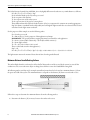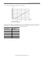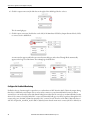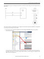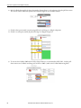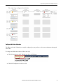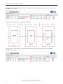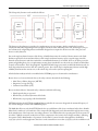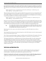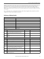
1
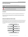
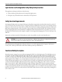
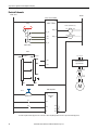
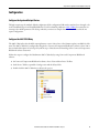
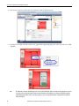
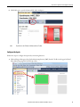
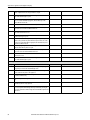
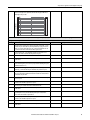
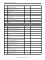
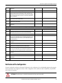
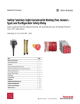
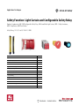
Application Technique
Safety Function: Light Curtain and Configurable Safety Relay
Products: Guardmaster 440C-CR30 Configurable Safety Relay, 440L GuardShield Light Curtain, 100S-C Safety Contactors,
800F E-Stop Button, 800F Reset Button
Safety Rating: CAT. 4, PLe to ISO 13849-1: 2008
Topic
Page
Important User Information
2
General Safety Information
3
Introduction
3
Safety Function Realization: Risk Assessment
3
Light Curtain and Configurable Safety Relay Safety Function
4
Safety Function Requirements
4
Functional Safety Description
4
Bill of Material
5
Setup and Wiring
5
Configuration
11
Calculation of the Performance Level
25
Verification and Validation Plan
28
Verification of the Configuration
33
Additional Resources
36
Safety Function: Light Curtain and Configurable Safety Relay
Important User Information
Read this document and the documents listed in the additional resources section about installation, configuration, and
operation of this equipment before you install, configure, operate, or maintain this product. Users are required to
familiarize themselves with installation and wiring instructions in addition to requirements of all applicable codes, laws,
and standards.
Activities including installation, adjustments, putting into service, use, assembly, disassembly, and maintenance are required
to be carried out by suitably trained personnel in accordance with applicable code of practice.
If this equipment is used in a manner not specified by the manufacturer, the protection provided by the equipment may be
impaired.
In no event will Rockwell Automation, Inc. be responsible or liable for indirect or consequential damages resulting from the
use or application of this equipment.
The examples and diagrams in this manual are included solely for illustrative purposes. Because of the many variables and
requirements associated with any particular installation, Rockwell Automation, Inc. cannot assume responsibility or
liability for actual use based on the examples and diagrams.
No patent liability is assumed by Rockwell Automation, Inc. with respect to use of information, circuits, equipment, or
software described in this manual.
Reproduction of the contents of this manual, in whole or in part, without written permission of Rockwell Automation,
Inc., is prohibited.
Throughout this manual, when necessary, we use notes to make you aware of safety considerations.
WARNING: Identifies information about practices or circumstances that can cause an explosion in a hazardous environment,
which may lead to personal injury or death, property damage, or economic loss.
ATTENTION: Identifies information about practices or circumstances that can lead to personal injury or death, property
damage, or economic loss. Attentions help you identify a hazard, avoid a hazard, and recognize the consequence.
IMPORTANT
Identifies information that is critical for successful application and understanding of the product.
Labels may also be on or inside the equipment to provide specific precautions.
SHOCK HAZARD: Labels may be on or inside the equipment, for example, a drive or motor, to alert people that dangerous
voltage may be present.
BURN HAZARD: Labels may be on or inside the equipment, for example, a drive or motor, to alert people that surfaces may
reach dangerous temperatures.
ARC FLASH HAZARD: Labels may be on or inside the equipment, for example, a motor control center, to alert people to
potential Arc Flash. Arc Flash will cause severe injury or death. Wear proper Personal Protective Equipment (PPE). Follow ALL
Regulatory requirements for safe work practices and for Personal Protective Equipment (PPE).
2
Rockwell Automation Publication SAFETY-AT138B-EN-P - May 2015
Safety Function: Light Curtain and Configurable Safety Relay
General Safety Information
Contact Rockwell Automation to find out more about our safety risk assessment services.
IMPORTANT
This application example is for advanced users and assumes that you are trained and experienced in safety system requirements.
ATTENTION: Perform a risk assessment to make sure all task and hazard combinations have been identified and addressed. The risk
assessment can require additional circuitry to reduce the risk to a tolerable level. Safety circuits must take into consideration safety
distance calculations, which are not part of the scope of this document.
Introduction
Light curtains are used to detect attempted access to a hazardous area. In normal operation, if a light curtain detects an
object, such as the operator's hand, it causes the safety system to stop any hazardous motion in the hazardous area.
This safety function application technique explains how to wire and configure a Point of Operation Control (POC)
GuardShield™ light curtain and an E-Stop function. The system is based on a Guardmaster® 440C-CR30 software
configurable safety relay.
Safety Function Realization: Risk Assessment
The required performance level is the result of a risk assessment and refers to the amount of the risk reduction to be carried
out by the safety-related parts of the control system. Part of the risk reduction process is to determine the safety functions of
the machine. In this application, the performance level required (PLr) by the risk assessment is Category 3, Performance
Level d (CAT. 3, PLd), for each safety function. A safety system that achieves CAT. 3, PLd, or higher, can be considered
control reliable. Each safety product has its own rating and can be combined to create a safety function that meets or
exceeds the PLr.
From: Risk Assessment (ISO 12100)
1. Identification of safety functions
2. Specification of characteristics of each function
3. Determination of required PL (PLr) for each safety function
To: Realization and PL Evaluation
Rockwell Automation Publication SAFETY-AT138B-EN-P - May 2015
3
Safety Function: Light Curtain and Configurable Safety Relay
Light Curtain and Configurable Safety Relay Safety Function
This application technique includes two safety functions:
1. Safety-related stop of hazardous motion, initiated by a light curtain.
2. Emergency stop of hazardous motion, initiated by an E-Stop button.
Safety Function Requirements
Interrupting the light curtain or pressing the Emergency Stop button stops and prevents hazardous motion by removal of
power to the motor. The motor then coasts to a stop (Stop Category 0). When the safety system is reset, hazardous motion
and power to the motor do not resume until a secondary action occurs (for example, pressing the start button). Faults at the
light curtain, wiring terminals, or safety controller are detected before the next safety demand. The safe distance from the
location of the light curtain to the hazard must be established such that the hazardous motion stops before you can reach
the hazard. The safety function in this example is capable of connecting and interrupting power to motors rated up to 9 A,
600V AC.
Position the reset button outside of the hazardous area where it is possible to view the entire hazardous area.
ATTENTION: If it is not possible to view the entire hazardous area, additional safety-rated presence-sensing devices must be used
to detect persons in that area, for example, by using a laser scanner or safety mat inside the cell.
The safety functions in this application technique each meet or exceed the requirements for Category 3, Performance
Level d (CAT. 3, PLd), per ISO 13849-1 and control reliable operation per ANSI B11.19.
Functional Safety Description
Hazardous motion is stopped or prevented by interrupting the field of view of the light curtain. The 440L light curtain is
connected to the 440C-CR30 configurable safety relay. The safety outputs of the 440C-CR30 relay control the power to
the 100S-C contactor coils. Whenever the 440C-CR30 relay de-energizes the safety contactors, the hazardous motion
coasts to a stop (Stop Category 0). The safety relay monitors the status of the 100S-C output contactors via mechanicallylinked auxiliary contacts and does not reset unless both sets of main motor contacts are open. After the load clears the light
curtain, all safety input signals are correct, no faults are detected, and the reset push button is pressed (for 0.25 to 3.0
seconds) and released, the 440C-CR30 relay turns its safety outputs ON, providing power to the contactor coils. The EStop is connected to the 440C-CR30 relay, which uses pulse checking to monitor the E-Stop for actuation and faults.
Whenever the E-Stop is actuated (pressed), the 440C-CR30 relay turns OFF its safety outputs, and the hazardous motion
is stopped. After the E-Stop button is released, all safety input signals are correct, no faults are detected, and the reset push
button is pressed (for 0.25 to 3.0 seconds) and released, the 440C-CR30 relay turns its safety outputs ON, providing power
to the contactor coils.
4
Rockwell Automation Publication SAFETY-AT138B-EN-P - May 2015
Safety Function: Light Curtain and Configurable Safety Relay
Bill of Material
This application uses these products.
Cat. No.
Description
Quantity
440C-CR30-22BBB
Guardmaster 440C-CR30 software-configured safety relay, PLe SIL 3, 22 safety I/O, embedded serial port, USB
programming port, 2 plug-in slots, 24V DC
1
2080-IQ4OB4
4-channel digital input/output combination module
1
440L-P4JL0640YD
GuardShield safety light curtain, resolution 14 mm, protective height 640 mm, 64 beams, integrated laser alignment
1
889D-F4AC-5
DC Micro (M12), female, straight, 4-pin, PVC cable, yellow, unshielded, 22 AWG, 5 meter (16.4 feet)
1
889D-F8AB-5
DC Micro (M12), female, straight, 8-Pin, PVC cable, black, unshielded, 24 AWG, 5 meter (16.4 feet)
1
800FP-MT44PX02S
800F non-Illuminated mushroom operators, twist to release, 40 mm, round plastic (type 4/4X/13, IP66), red, plastic latch
mount, 0 N.O. contacts, 2 N.C. contacts, self-monitoring, standard pack
1
800FP-F611PX10
800F push button - plastic, flush, blue, R, plastic latch mount, 1 N.O. contacts, 0 N.C. contacts, standard, standard pack
1
100S-C09EJ23C
MCS 100S-C safety contactor, 9 A, 24V DC (with electronic coil)
2
Setup and Wiring
For detailed information on installing and wiring, refer to the publications listed in the Additional Resources on the back
cover.
System Overview
When an object, such as the operator's hand, interrupts the light curtain, the light curtain turns its two OSSD outputs
OFF. These signals are connected to the safety input terminals of the 440C-CR30 safety relay. When the light curtain's
OSSD outputs turn OFF, the safety relay responds by turning OFF its own redundant safety outputs. This action removes
the 24V signal from the coils of the two safety contactors whose main motor contacts then open, thus removing power
from the motor. This action causes the motor to coast to a stop (Stop Category 0). Stopped is the safe state.
The 100S-C safety contactors are the final control devices. A 24V signal is passed through mechanically-linked, normallyclosed (N.C.) auxiliary contacts of the 100S-C contactors to inputs on the 440C-CR30 safety relay, enabling the relay to
monitor the status of the main contacts. This 24V feedback (monitoring) signal is only present at the safety relay's inputs if
the main contacts are open, meaning that the contactors are in a safe state. If one of the main motor contacts is welded shut,
the auxiliary N.C. contacts are held open by the mechanical linkage and the 24V feedback signal does not reach the inputs
of the safety relay. The safety relay does NOT reset under this condition. The failed contactor would have to be replaced.
After the load clears the light curtain, the light curtain’s OSSD outputs turn ON. When the safety relay detects these
signals and the feedback monitoring signal, when no faults are detected, and the reset push button is pressed (for 0.25 to 3.0
seconds) and released, the 440C-CR30 relay turns its safety outputs ON, providing power to the contactor coils. Position
the reset button where it is possible for the operator to view the entire hazardous area. If a person is in the hazardous area,
the reset button should not be pressed. If it is not possible to view the entire accessible hazardous area when operating the
reset button, use supplemental safeguarding, such as a safety mat or a laser scanner to monitor the hazardous area. Another
option is to use mechanical implementations that make it impossible to be in the hazardous area without interrupting the
light curtain.
Rockwell Automation Publication SAFETY-AT138B-EN-P - May 2015
5
Safety Function: Light Curtain and Configurable Safety Relay
The reset button and contactor feedback-monitoring circuits connect to the 2080 plug-in I/O module. This module is not
safety rated. It is acceptable to use standard inputs for the reset and feedback because they are not safety-rated signals. They
are simple 24V signals. The 440C-CR30 safety relay limits the use of standard I/O to functionality that does not require
safety rated signals. By comparison, the E-Stop and light curtain signals must not be connected to the standard I/O plug-in
module. These signals must be connected to safety-rated inputs. Both the configuration software and the firmware prevent
you from using standard inputs for signals that must be safety rated. Reset and feedback monitoring signals can be
connected to safety rated inputs if so desired. This example uses the 2080 plug-in I/O module to show the capability of the
440C-CR30 safety relay.
The light curtain monitors its internal circuitry and its OSSD outputs for faults. When the light curtain detects a fault in
the internal circuitry, the light curtain responds by turning its OSSD outputs OFF. A fault on the OSSD outputs is
detected either immediately, or upon the next safety demand. The light curtain turns its OSSD outputs OFF when it
detects an output fault, such as a short-circuit to another signal, or between the two OSSD channels. Most internal and
wiring faults of the light curtain require you to cycle power after removing the cause of the fault to internally clear the fault
and enable the light curtain to turn its outputs ON.
The 440C-CR30 safety relay sends test pulse signals from multi-purpose terminals 12 and 13 through the contacts of the
E-Stop, which are connected back to the safety inputs on the safety relay. Pressing the E-Stop interrupts this circuit. The
safety relay responds by turning its safety outputs OFF, which de-energize the coils of the 100S-C contactors. This causes
the main motor contacts to open, removing power from the motor and causing it to coast to a stop (Stop Category 0).
The 440C-CR30 safety relay monitors the E-Stop circuit for faults. Loose wires, shorts to 24V, shorts to ground, contacts
failed closed, and cross faults are detected. When a fault is detected, the safety relay responds by turning its safety outputs
OFF, taking the system to a safe state.
The 440C-CR30 safety relay checks itself for internal faults and turns its outputs off, if any are detected.
No single fault results in the safety system failing to perform its safety function. A single fault is detected before or upon the
next demand on the safety system. The system cannot be reset until the fault is corrected.
When a light curtain is used, additional mechanical protective devices must be installed so that hazardous machine
elements cannot be reached by personnel or material without first passing through the protective field of the light curtain.
For example, the entire rest of the hazardous cell should be surrounded by expanded metal fencing of sufficient height and/
or interlocked gates, including the area above and beneath the protective area of the light curtain, if it would otherwise be
possible for a person to access the hazard through these spaces. Refer to the relevant standards and the GuardShield Type 4
and GuardShield Remote Teach User Manual, publication 440L-UM003, for additional information on how to position
the light curtain.
The selection of light curtain model, protective height, resolution, and other specifications is dependent on the results of
the risk assessment for the specific application. Refer to the relevant standards and the GuardShield Type 4 and
GuardShield Remote Teach User Manual, publication 440L-UM003, for additional information. These factors also affect
the safety distance calculation.
IMPORTANT
6
An example calculation is shown in this document, but you must perform a final calculation for your specific application based on
the safety system specification, as well as the machine stopping time.
Rockwell Automation Publication SAFETY-AT138B-EN-P - May 2015
Safety Function: Light Curtain and Configurable Safety Relay
Safety Distance Calculation
A safety light curtain provides no physical barrier between a person and the hazardous motion. The safety light curtain
must be installed at a sufficient distance from the hazardous motion to make sure that someone putting a hand through the
light curtain cannot reach the hazard before it has stopped. This distance is referred to as the Safety Distance. The Safety
Distance (S or Ds) required varies from installation to installation, and therefore must be calculated for each specific
application. This application technique provides example calculations based on the formulae from both the international
standard ISO 13855 and the U.S. standard ANSI B11:19.
The Safety Distance formula for vertically installed safety light curtains from ISO 13855:
S = (K x T) + C
S: the minimum distance, in millimeters (mm)
K: a parameter, in millimeters per second (mm/s), derived from data on approach speeds of the body or parts of the
body
T: the overall stopping performance in second(s) based on the machine stopping time plus the safety system total
reaction time
C: the intrusion distance in millimeters (mm)
For the purposes of this example, we use the following values:
K = 2000 mm per second; or, when S > 500 mm, K =1600 mm per second (when using the latter, a minimum S of
500 mm must be used)
T = 410 ms [300 ms (machine stopping time) + 20 ms (light curtain) + 45 ms (440C-CR30 relay) + 45 ms (K1 and
K2 contactors)]
IMPORTANT: The specific machine stopping time must be measured for each application.
C = 0 mm [8 x (d-14) but not less than 0 where d is the resolution of the light curtain (d=14 mm)]
S = (K x T) + C = 2000 mm/s x 0.41 s + 0 mm = 820 mm.
Since 820 mm > 500 mm, we repeat the calculation using K = 1600 mm/s.
S = (K x T) + C = 1600 mm/s x 0.41 s + 0 mm = 656 mm
IMPORTANT: If the calculation of S results in a value less than 500 mm when using K = 1600 mm/s, a safety
distance of 500 mm must be used.
The light curtain must not be mounted closer than 656 mm (approx. 26 in.) from the hazardous motion being guarded
against.
IMPORTANT
For Point of Operation Control Light Curtain applications, the machine stopping time is critical–the machine must be capable of
stopping in a very short period of time. In the example, we use a machine stopping time of 300 ms. The machine must stop within
300 ms every time to be able to use this number. By comparison, if the stopping time was 500 ms, the safety distance would be
976 mm. The light curtain would need to be mounted 320 mm farther away from the hazard just because it takes 0.2 seconds
longer to stop. It is very important to understand the effect that stopping time has on the safety distance.
Rockwell Automation Publication SAFETY-AT138B-EN-P - May 2015
7
Safety Function: Light Curtain and Configurable Safety Relay
The Safety Distance formula from ANSI B11:19 is only slightly different and results in a very similar distance, as follows:
Ds = K x (Ts + Tc + Tr + Tbm) + Dpf.
K: the ‘standard’ hand speed of 63 inches per second
Ts: the stop time of the machine
Tc: the response time of the safety system
Tr: the response time of the presence sensing device
Tbm: additional time allowed for the brake monitor (if any) to compensate for variations in normal stopping time
Dpf : the distance a ‘standard’ hand could possibly move through the light curtain before it is detected. This is a fixed
value based on the light curtain resolution.
For the purposes of this example, we use the following values:
K = 63 inches per second
Ts = 300 ms (0.3 sec.) for the purposes of this application technique.
IMPORTANT: The specific machine stopping time must be measured for each application.
Tc = 90 ms = 45 ms (440C-CR30 relay) + 45 ms (K1 and K2 contactors)
Tr = 20 ms (light curtain)
Tr + Tc = 90 + 20 = 110 ms = 0.11 second
Tbm = 0 (No brake is used in this application.)
Dpf = 1 in.
Ds = K x (Ts + Tc + Tr + Tbm) + Dpf = 63 x (0.3 + 0.09 + 0.02 + 0) + 1 = 63 x 0.41 + 1 = 26.8 in.
The light curtain must not be mounted closer than 26.8 in. from the guarded hazard.
Minimum Distance from Reflecting Surfaces
The infrared light from the sender may be reflected off of shiny surfaces and be received by the system’s receiver. If this
condition occurs, it can result in an object not being detected when it enters the GuardShield sensing field.
All reflecting surfaces and objects (for example, material bins) must therefore be located at a minimum distance (a) from
the protective field of the system. The minimum distance a depends on the distance (D) between sender and receiver.
a
Distance D (meters)
Follow these steps to determine the minimum distance from the reflecting surfaces.
1. Determine the distance, (D) in meters, between the sender and receiver.
8
Rockwell Automation Publication SAFETY-AT138B-EN-P - May 2015
Safety Function: Light Curtain and Configurable Safety Relay
2. Read the minimum distance, (a) in millimeters, from the graph.
a [mm]
D [m]
a = minimum distance to reflecting surfaces
D = distance between transmitter and receiver
The effective aperture angle for the GuardShield system is ± 2.5° at a mounting distance of > 3.0 m (9.8 ft). Calculate the
minimum distance to reflecting surfaces depending on the distance between the transmitter and the receiver, using an
aperture angle of ± 2.5°, or take the appropriate value from the following table.
Distance between transmitter
and receiver [m (ft)]
MInimum distance to reflecting
surface [mm (in.)]
0.2…3.0 (0.65…9.8)
135 (5.31)
4.0 (13.1)
175 (6.88)
5.0 (16.4)
220 (8.66)
6.0 (19.6)
265 (10.43)
7.0 (22.9)
310 (12.2)
10.0 (32.8)
440 (17.32)
16.0 (52.4)
700 (27.55)
Rockwell Automation Publication SAFETY-AT138B-EN-P - May 2015
9
Safety Function: Light Curtain and Configurable Safety Relay
Electrical Schematic
24V DCDC
- Class
2
24V
- Class
2
COM
DCDCCOM
440C-CR30-22BBB
A1
E-Stop
E-Stop
A2
440C-CR30
100S-CxxEJx* (2)
EO_18
A1
K1
A2
MP_12
EI_00
EO_19
A1
K2
A2
EI_01
MP_13
800Fx-MTx
440L
Brown
Brn
Transmitter
Transmitter
Brown
Brn
L1 L2 L3
Receiver
Receiver
Pink
Pnk
Gray
Gry
EI_02
External
External Switched
Switched
Stop/Start Circuit
Stop/Start
Circuit
EI_03
K1
Green
Grn
Blue
Blu
K2
Blue
Blu
M
2080-IQ4OB4
Reset
Reset
I-00
800Fx-F6x
K1
K2
Plug-in I/O
Plug-In
I/O
Slot 2
Slot
2
I-01
I-02
A4
A3
B4
B3
13849-2
requires transient
suppression
across
the as
loada as
a Basic
SafetyPrincipal.
Principal. TheThe
'EJ'“EJ”
electronic
coil provides
suppression.
*ISO 13849-2 *ISO
requires
transient
suppression
across
load
Basic
Safety
electronic
coil suitable
provides
suitable suppression.
10
Rockwell Automation Publication SAFETY-AT138B-EN-P - May 2015
Safety Function: Light Curtain and Configurable Safety Relay
Configuration
Configure the Input and Output Devices
The light curtain uses the standard, default configuration. If the configuration DIP switches may have been changed, refer
to the GuardShield Type 4 and GuardShield Remote Teach User Manual, publication 440L-UM003, for instructions on
resetting to the default parameters. The E-Stop and safety contactors are simple electromechanical devices that do not
require configuration.
Configure the 440C-CR30 Relay
The 440C-CR30 safety relay should be running firmware version 7.00 or later. A free firmware update is available for older
units. The 440C-CR30 relay is configured by using the free Connected Components Workbench™ software, release 7.00 or
later. A detailed description of each step is beyond the scope of this document. Knowledge of the Connected Components
Workbench software is assumed.
Follow these steps to configure the Guardmaster 440C-CR30 relay by using Connected Components Workbench
software.
1. In Connected Components Workbench software, choose View and then Device Toolbox.
2. In the Device Toolbox, expand the Catalog section and the Safety folder.
3. Double-click the 440C-CR30 relay to add it to the project.
Rockwell Automation Publication SAFETY-AT138B-EN-P - May 2015
11
Safety Function: Light Curtain and Configurable Safety Relay
4. In the Project Organizer, double-click the Guardmaster 440C-CR30 safety relay.
5. To add the I/O module called for in this circuit, right-click the right-hand plug-in slot of the relay, and choose 2080IQ4OB4.
TIP
12
The I/O module is shown in standard gray because it is not a safety I/O module. That is permissible in this application because it is
not used to connect safety-rated signals. Inputs such as Reset buttons and Feedback are not safety-rated signals. By using the
standard I/O plug-in module for these non-safety signals, you can reserve the limited number of safety inputs and outputs for
safety-rated signals.
Rockwell Automation Publication SAFETY-AT138B-EN-P - May 2015
Safety Function: Light Curtain and Configurable Safety Relay
6. Click Edit Logic to open the function block editor workspace.
TIP
If you don't see the Toolbox, click View and choose Toolbox.
Configure the Inputs
Follow these steps to configure the input safety monitoring functions.
1. Click and drag an Emergency Stop Safety Monitoring function (SMF) from the Toolbox to the upper left-hand
Safety Monitoring target block in the logic editor.
Rockwell Automation Publication SAFETY-AT138B-EN-P - May 2015
13
Safety Function: Light Curtain and Configurable Safety Relay
Connected Components Workbench software automatically assigns the next available terminals for both the inputs
and the test sources. Any necessary configuration of those I/O points is also done automatically by the software. In
this case, the default assignments are correct and no terminal changes are required for this application.
2. In the Toolbox, click and drag Light Curtain to the target block below the E-Stop SMF 1.
3. To add a Reset safety monitoring function, click and drag a Reset from the Toolbox to the target block below the
Light Curtain SMF 2.
4. On the Reset SMF 3, click the input terminal EI_04 and select Plug-in 2 Inputs P2_00.
14
Rockwell Automation Publication SAFETY-AT138B-EN-P - May 2015
Safety Function: Light Curtain and Configurable Safety Relay
Note that the reset can come from a standard plug-in input or even from the serial port, via a Modbus message.
Configure the Outputs
Follow these steps to configure the Safety Output Function (SOF).
1. In the Toolbox under Safety Output Function Blocks, click and drag Immediate OFF to the first Safety Output
function target on the logic editor.
Connected Components Workbench software automatically assigns the first two available safety output terminals of
the 440C-CR30 relay, EO_18 and EO_19 (embedded safety outputs 18 and 19, respectively). These outputs drive
the two 100S-C safety contactors. The PT to the right of the terminal assignment stands for Pulse Testing, a
technique used to detect if the output terminal is short-circuited to 24V DC or another safety output terminal.
Other output terminals have additional options for configuration besides Pulse Testing, but for terminals 18 and 19,
it is the only possible configuration.
Rockwell Automation Publication SAFETY-AT138B-EN-P - May 2015
15
Safety Function: Light Curtain and Configurable Safety Relay
2. From the Reset Input pull-down menu on the Safety Output Function (SOF), choose SMF3 to use the Reset we set
up in the previous section.
Configure the Logic
In this application, pressing the Emergency Stop disconnects power from the motor. An interruption of the light curtain
also disconnects power from the motor. Using an AND function configures the outputs of the 440C-CR30 relay to turn
ON, allowing the system to run when the E-Stop is closed, that is when the N.C. E-Stop button is released and clear, and
the light curtain is also clear.
1. In the Toolbox, under the Logic Functions, click and drag an AND logic block onto the first Logic Level A target
block.
2. Click the output connection of the E-Stop SMF 1, which is the blue dot on the right of the block.
The dot turns light gray, indicating that it is selected.
16
Rockwell Automation Publication SAFETY-AT138B-EN-P - May 2015
Safety Function: Light Curtain and Configurable Safety Relay
3. Click the first input connection (blue dot) of the AND block to connect it to the E-Stop block.
A connection line appears and both connection dots turn dark gray. The logic looks like this:
4. Click the blue dot on the right side of the Light Curtain (SMF2) block, which is the output connection.
The dot turns light gray, indicating that it is selected.
5. Click the second input connection (blue dot) of the AND block to connect it to the Light Curtain SMF 2.
A connection line appears and both dots turn dark gray.
Rockwell Automation Publication SAFETY-AT138B-EN-P - May 2015
17
Safety Function: Light Curtain and Configurable Safety Relay
6. Click the output connection (the blue dot on the right) of the AND logic block to select it.
The dot turns light gray.
7. Click the input connection (the blue dot on the left) of the Immediate OFF Safety Output Function block, SOF1,
to connect it to the AND block.
A connection line appears and both connection dots turn dark gray. Also, a Pass Through block automatically
appears in the Logic Level B column. The resulting logic looks like this:
Configure the Feedback Monitoring
Feedback is the act of monitoring the output device to confirm that it is OFF when the 440C-CR30 relay output driving
that device is OFF. Safety-rated output devices, such as safety contactors, use mechanically-linked contacts so that an
external device can monitor their status. Mechanical linkage means that all of the contacts are mechanically linked so that
when a N.O. contact is closed, the linked N.C. contact is mechanically held open. A 24V DC signal sent through the N.C.
contact only gets to the 440C-CR30 relay input if the N.C. contact is closed. Therefore, if the 440C-CR30 relay detects
24V DC on inputs P2_01 and P2_02, the 440C-CR30 relay knows that the main motor contacts (the N.O. channels) are
18
Rockwell Automation Publication SAFETY-AT138B-EN-P - May 2015
Safety Function: Light Curtain and Configurable Safety Relay
open, and therefore no power is reaching the motor, which is considered a safe state. That portion of the wiring schematic is
shown below.
24V DC
Plug-in I/O
Slot 2
External Switched
Stop/Start Circuit
For the 440C-CR30 relay, Feedback Monitoring is configured as a Safety Monitoring Function (SMF) that is subsequently
associated with a Safety Output Function (SOF).
1. In the Toolbox, under Safety Monitoring Functions, click and drag Feedback Monitoring to the target block
underneath the Reset block.
Connected Components Workbench software automatically assigns the next available terminal. In this application,
the feedback monitoring circuit is wired into plug-in inputs 01 and 02, so you must change the configuration of this
SMF and the terminal assignments.
Rockwell Automation Publication SAFETY-AT138B-EN-P - May 2015
19
Safety Function: Light Curtain and Configurable Safety Relay
2. In the Feedback function block, change the number of inputs from 1 to 2 by selecting 2 from the pull-down menu.
The software adds an additional input and automatically assigns the next available terminal.
3. Click the first input terminal (currently assigned EI_04) and change it to Plug-In 2 Inputs 01.
4. Click the second input terminal (EI_05) and change it to Plug-In 2 Inputs 02.
5. To associate this Feedback SMF with the Safety Output Function, on the Immediate OFF SOF 1, click the pulldown menu next to Feedback and change it from None to SMF 4, which is the Feedback Monitoring block.
20
Rockwell Automation Publication SAFETY-AT138B-EN-P - May 2015
Safety Function: Light Curtain and Configurable Safety Relay
The complete logic configuration looks like this.
Configure the Status Indicators
The LEDs on the 440C-CR30 relay can easily be configured, per your preference, to show more information than typical
status LEDs.
To configure the LED status indicators, follow these steps:
1. Click the Guardmaster_440C_CR30 Project tab on the Workspace.
2. Click LED Configuration on the lower left.
Rockwell Automation Publication SAFETY-AT138B-EN-P - May 2015
21
Safety Function: Light Curtain and Configurable Safety Relay
3. Configure the Type Filter and Value for each LED status indicator as shown in Table 1.
Table 1 - Status Indicator Settings
Input LEDs
Type Filter
Value
Notes
0
Terminal Status
Terminal 00
E-Stop Channel 1
1
Terminal Status
Terminal 01
E-Stop Channel 2
2
Terminal Status
Terminal 02
Light Curtain OSSD A
3
Terminal Status
Terminal 03
Light Curtain OSSD B
4-9
Not Used
Not Used
Output LEDs
Type Filter
Value
Notes
0
Safety Output Function
SOF 1
Safety Outputs 18 and 19
1-5
Not Used
Not Used
Confirm the Validity of the Build
Follow these steps to confirm the validity of the logic by using the Build feature in Connected Components Workbench
software.
1. Click Guardmaster_440C_CR30 in the bar above the Workspace.
22
Rockwell Automation Publication SAFETY-AT138B-EN-P - May 2015
Safety Function: Light Curtain and Configurable Safety Relay
2. Click Build.
A Build Succeeded message confirms that the configuration is valid.
If an error or omission is discovered during a build, a message is displayed which details the error so that it may be
corrected. After you correct the error, you must perform the build again.
Save and Download the Project
Follow these steps to save and download the project.
1. From the File menu, choose Save as to save the project.
IMPORTANT
Saving the project with a new name closes the workspace window.
2. In the Project Organizer window, double-click Guardmaster_440C_CR30 to open the workspace.
3. Power up the 440C-CR30 safety relay.
4. Connect the USB cable to the 440C-CR30 relay.
Rockwell Automation Publication SAFETY-AT138B-EN-P - May 2015
23
Safety Function: Light Curtain and Configurable Safety Relay
5. Click Download.
6. In the Connection Browser, expand the AB_VBP-1 Virtual Chassis and select the Guardmaster 440C-CR3022BBB.
7. Click OK.
8. Click Yes to change from Run to Program mode.
9. When the download is complete, click Yes to change from Program to Run mode.
24
Rockwell Automation Publication SAFETY-AT138B-EN-P - May 2015
Safety Function: Light Curtain and Configurable Safety Relay
10. Click Edit Logic to see the online diagnostics.
Green indicates that a block is True or that an input or output terminal is ON. Flashing green indicates that a Safety
Output Function is ready to be Reset. The complete safety system must be installed and powered up to fully use the
online diagnostics mode.
The online diagnostics mode of the 440C-CR30 relay can be very helpful during the verification process.
11. Review the information in Calculation of the Performance Level on page 25 and Verification and Validation Plan on
page 28 before proceeding with Verification of the Configuration on page 33.
Calculation of the Performance Level
When properly implemented, the light curtain and E-Stop safety functions can achieve a safety rating of Category 4,
Performance Level e (CAT. 4, PLe), according to ISO 13849-1: 2008, as calculated by using the SISTEMA software PL
calculation tool.
The Performance Level required (PLr) from the risk assessment for each of the safety functions in this application is PLd or
better. Additionally each safety function must achieve a CAT. 3 rating or better in order to be considered Control Reliable
per ANSI B11.19.
Rockwell Automation Publication SAFETY-AT138B-EN-P - May 2015
25
Safety Function: Light Curtain and Configurable Safety Relay
The Performance Level and Category achieved by each subsystem of the light curtain safety function, as calculated by
SISTEMA, is shown below.
The light curtain safety function can be modeled as follows.
Input
Logic
Output
100S-C
K1
GuardShield
Light Curtain
440C-CR30
Relay
100S-C
K2
Subsystem 1
Subsystem 2
Subsystem 3
The Performance Level and Category achieved by each subsystem of the E-Stop safety function, as calculated by
SISTEMA, is shown below.
26
Rockwell Automation Publication SAFETY-AT138B-EN-P - May 2015
Safety Function: Light Curtain and Configurable Safety Relay
The E-Stop safety function can be modeled as follows.
Logic
Input
100S-C
K1
E-Stop
Channel 1
Fault
Exclusion
440C-CR30
Relay
100S-C
K2
E-Stop
Channel 2
Subsystem 1
Output
Subsystem 2
Subsystem 3
Subsystem 4
The Emergency Stop function is considered a complementary protective measure, which is intended to be used in
conjunction with other safeguarding measures and protective devices that sufficiently reduce risk. An Emergency Stop is
not a substitute for safeguarding measures and shall be designed not to impair the effectiveness of the other protective
devices or safety functions.
Due to the single mechanical actuator of the E-Stop, a Fault Exclusion must be considered. In most instances the Fault
Exclusion required for electromechanical devices with a single mechanical actuator, such as a typical tongue interlock,
limits the safety function in which it is included to a maximum Performance Level of PLd; however, the E-Stop is not the
primary safeguarding device. It is a complementary measure that is intended for use only in the case of unforeseeable failure
or misuse of the machine. The E-Stop's high DC, high MTTFd and Category 4 structure would, Fault Exclusion aside, let
the E-Stop safety function achieve PLe. It is common practice, due to the E-Stop's complementary function and the high
reliability demonstrated in extensive use, to allow the E-Stop to be used in systems requiring PLe.
A Fault Exclusion subsystem has been included in the SISTEMA project to document this consideration.
Because these are electro-mechanical devices, the safety contactor data includes the following:
• Mean Time to Failure, dangerous (MTTFd)
• Diagnostic Coverage (DCavg)
• Common Cause Failure (CCF)
Electro-mechanical devices' functional safety evaluations include the following:
• How frequently they are operated
• Whether they are effectively monitored for faults
• Whether they are properly specified and installed
SISTEMA calculates the MTTFd by using B10d data provided for the contactors along with the estimated frequency of
use, entered during the creation of the SISTEMA project.
The B10d data affects not only the MTTFd, but also the expected lifetime of the electro-mechanical safety device. B10d is
defined as the number of cycles until 10% of the components fail dangerously and is determined through extensive testing
by the manufacturer of the component. According to Annex C.4.2 of ISO 13849-1, the operating time of a device must not
exceed the T10d (the mean time it takes for 10% of the components in the system to have a dangerous failure), following
the equation T10d = B10d/number of operations. For the 100S-C contactors used in this application, the B10d is
1,333,333 cycles. For a safety application, this device can be actuated for no more than 1,333,333 cycles. It would then need
Rockwell Automation Publication SAFETY-AT138B-EN-P - May 2015
27
Safety Function: Light Curtain and Configurable Safety Relay
to be replaced. To convert this into a time period, we divide by the number of operations. For example, if we expect that the
light curtain will be interrupted every ten minutes (that is, 6 times per hour) in an application that will operate 24 hours per
day, 365 days per year, the total number of operations (annual cycles) of the 100S-C contactors would be 52,560 cycles per
year.
Number of Operations (nop) = 6 operations/hour x 24 hours/day x 365 days/year = 52,560 cycles per year
T10d = B10d/nop = 1,333,333/52,560 = 25.4 years
This means that the operation time of these components is limited to 25.4 years. Since 25.4 years are longer than the typical
estimated system lifetime of 20 years, this number of operations is acceptable. However, if operation was more frequent
there would be a challenge. As an example, here are the same calculations if we expected the light curtain to be interrupted
every five minutes (instead of every ten minutes) with 24/7/365 operation:
Number of Operations (nop) = 12 operations/hour x 24 hours/day x 365 days/year = 105,120 cycles per year
T10d = B10d/nop = 1,333,333/105,120 = 12.7 years
Because 12.7 years are less than the typical system lifetime of 20 years, the user of the machine must be instructed to replace
the 100S-C contactors after 12.7 years, assuming the actual frequency of operation matched the original estimate. It would
also be good practice to advise the user of the impact of the number of operations of the electro-mechanical device, which
in turn is driven by how frequently the safety devices are actuated, for example, by interrupting the light curtain.
TIP
Use of an output control device with its own electronic safety monitoring, such as a Variable Frequency Drive with a modern Safe
Torque-off implementation, eliminates the need for calculation of lifetime based on number of operations, as that type of device
has a defined lifetime that is not dependent on the number of cycles.
The DCavg (99%) for the contactors is selected from the Output Device table of ISO 13849-1 Annex E, Direct
Monitoring.
The DCavg (99%) for the E-stop is selected from the Input Device table of ISO 13849-1 Annex E, Cross Monitoring with
detection of static faults and short circuits.
The CCF value is generated by using the scoring process outlined in Annex F of ISO 13849-1. The complete CCF scoring
process must be performed when actually implementing an application. A minimum score of 65 must be achieved.
The Emergency Stop function is a complementary protective measure which is intended to be used in conjunction with
other safeguarding measures and protective devices to sufficiently reduce risk. The emergency stop function shall be
designed not to impair the effectiveness of the other protective devices or safety functions. For emergency stop devices in
accordance with IEC 60947-5-5, a fault exclusion for mechanical aspects is allowed up to PLe if the maximum number of
operations is considered. However, the actual number of operations (NOP) is used for the purposes of the MTTFd
calculation in this document.
Verification and Validation Plan
Verification and validation play important roles in the avoidance of faults throughout the safety system design and
development process. ISO 13849-2 sets the requirements for verification and validation. The standard calls for a
documented plan to confirm that all of the safety functional requirements have been met.
Verification is an analysis of the resulting safety control system. The Performance Level (PL) of the safety control system is
calculated to confirm that the system meets the required Performance Level (PLr) specified. The SISTEMA software is
typically used to perform the calculations and assist with satisfying the requirements of ISO 13849-1.
28
Rockwell Automation Publication SAFETY-AT138B-EN-P - May 2015
Safety Function: Light Curtain and Configurable Safety Relay
Validation is a functional test of the safety control system to demonstrate that the system meets the specified requirements
of the safety function. The safety control system is tested to confirm that all of the safety-related outputs respond
appropriately to their corresponding safety-related inputs. The functional test includes normal operating conditions in
addition to potential fault injection of failure modes. A checklist is typically used to document the validation of the safety
control system.
Prior to validating the system, confirm that the Guardmaster 440C-CR30 configurable safety relay has been wired and
configured in accordance with the installation instructions.
Verification and Validation Checklist
General Machinery Information
Machine Name/Model Number
Machine Serial Number
Customer Name
Test Date
Tester Name
Schematic Drawing Number
Input Devices
800FP-MT44 (E-Stop), 800FP-F611 (Reset), 440L-P4JL0640YD (Light Curtain)
Configurable Safety Relay
440C-CR30-22BBB
Safety Contactor
100S-C09EJ23C (x2)
Safety Wiring and Relay Configuration Verification
Test Step
Verification
Pass/Fail
1
Confirm that all components' specifications are suitable for the application. Refer to
Basic Safety Principles and Well-tried Safety Principles from ISO 13849-2.
2
Visually inspect the safety relay circuit to confirm that it is wired as documented in the
schematics.
3
Confirm that the configuration in the 440C-CR30 relay is the correct, intended
configuration.
Changes/Modifications
Normal Operation Verification - The safety system responds properly to all normal Start, Stop, Reset, E-stop, and Light Curtain inputs.
Test Step
Verification
Pass/Fail
1
Confirm that no one is in the guarded area.
2
Confirm that the motor is stopped.
3
Confirm that the E-Stop is released.
4
Confirm that the light curtain is clear.
5
Apply power to the safety system.
6
Confirm that the E-Stop and light curtain input indicator LEDs of the 440C-CR30 relay
are ON. Confirm that the Power status and Run status indicator LEDs are green. (The
Run status indicator can be flashing green to indicate a non-verified project.)
7
Press and release the Reset Button. Confirm that the 440C-CR30 relay output status
indicator LED indicator OUT 0 is ON (status of SOF 1).
8
Confirm that the motor does not start.
9
Use the standard control system to start the machine. Confirm that the motor starts
and the machine begins to operate.
Rockwell Automation Publication SAFETY-AT138B-EN-P - May 2015
Changes/Modifications
29
Safety Function: Light Curtain and Configurable Safety Relay
10
Use the standard control system to stop the machine. The machine must stop in its
normal, configured manner. The safety system must not respond.
11
Use the standard control system to start the machine again. Confirm that the motor
starts and the machine begins to operate.
12
Press the E-Stop button. The safety system must trip. The machine must stop in less
than 0.4 seconds (the maximum stopping time). The 440C-CR30 relay’s status
indicator LED OUT 0 must be OFF.
13
Press and release the Reset button. The 440C-CR30 relay must not respond.
14
Release the E-Stop button. The machine must not start. The 440C-CR30 relay must not
respond. The OUT 0 status indicator LED must remain OFF.
15
Press and release the Reset button. The 440C-CR30 relay’s OUT 0 status indicator LED
turns ON. The machine must not start.
16
Use the standard control system to start the machine. Confirm that the motor starts
and the machine begins to operate.
17
Use a test rod, included with the light curtain, to interrupt the light curtain protective
field. The safety system must trip. The machine must stop in less than 0.41 seconds
(system response time plus maximum stopping time). The 440C-CR30 relay’s OUT 0
status indicator LED must turn OFF.
18
While interrupting the light curtain with the test rod, press and release the Reset
button. The 440C-CR30 relay must not respond.
19
Clear the light curtain. The machine must not start. The 440C-CR30 relay must not
respond - the OUT 0 status indicator LED must remain OFF.
20
Press and release the Reset button. The OUT 0 status indicator LED must turn ON. The
machine must not start.
21
Use the standard control system to start the machine again. Confirm that the motor
starts and the machine begins to operate.
Normal Light Curtain Verification
Test Step
Verification
1
Confirm that access to the hazardous machine parts is only possible via passage
through the protective field of the GuardShield light curtain.
2
Confirm that the distance from the light curtain to any hazard in the cell is greater
than the calculated safety distance of the application.
3
Confirm that the optic front covers of both the light curtain transmitter and receiver
are neither scratched nor dirty.
4
Disconnect 24V power from the light curtain and confirm that the 440C-CR30 relay
trips.
5
Reconnect 24V power to the light curtain. Push the Reset button. Confirm that the
440C-CR30 relay turns its safety outputs ON.
6
Use the test rod to confirm that the OSSD outputs of the light curtain are OFF when
the test rod is anywhere within the light curtain's protective field by observing the
status of the output indicator LEDs on the light curtain and 440C-CR30 relay IN 2 and 3
LED indicators.
30
Pass/Fail
Rockwell Automation Publication SAFETY-AT138B-EN-P - May 2015
Changes/Modifications
Safety Function: Light Curtain and Configurable Safety Relay
Pass the test rod through the protective field as shown in the attached illustration.
Confirm that the light curtain output LEDs and 440C-CR30 relay input LEDs remain
OFF throughout the procedure.
Receiver
Transmitter
7
Validation of Safe Response to Abnormal Operation - The safety system responds properly to all foreseeable faults with corresponding diagnostics.
E-stop, 440C-CR30 Relay Tests
Test Step
Validation
Pass/Fail
1
While the machine is running, remove the E-Stop input wire at terminal EI_00 of the
440C-CR30 relay. The 440C-CR30 relay must trip immediately, stopping the machine
within 0.4 seconds. The 440C-CR30 relay’s OUT 0 status indicator LED must turn OFF.
The red Fault status indicator LED of the 440C-CR30 relay must flash.
2
Reconnect the wire to EI_00. The 440C-CR30 relay must not respond. Press and
release the Reset button. The 440C-CR30 relay must not respond.
3
Cycle the E-Stop. The red Fault status indicator LED should turn OFF.
4
Press and release the Reset button. The 440C-CR30 relay’s OUT 0 status indicator LED
should turn ON.
5
Use the standard control system to start the machine. Confirm that the motor starts
and the machine begins to operate. (This step is optional in the following E-Stop and
GuardShield validation tests.)
6
While the motor is running, jump the E-Stop input wire at terminal MP_12 to
terminal EI_00 of the 440C-CR30 relay. The 440C-CR30 relay should not respond.
7
Press the E-Stop button. The 440C-CR30 relay must trip immediately. The 440C-CR30
relay’s OUT 0 status indicator LED must turn OFF. The red Fault status indicator LED of
the 440C-CR30 relay must flash.
8
Release the E-Stop button. Press and release the Reset button. The 440C-CR30 relay
must not respond.
9
Remove the jumper. The 440C-CR30 relay must not respond. Press and release the
Reset button. The 440C-CR30 relay must not respond.
10
Cycle the E-Stop. The red Fault status indicator LED should turn OFF.
11
Press and release the Reset button. The 440C-CR30 relay’s OUT 0 status indicator LED
should turn ON.
12
Short the E-Stop input wire at terminal EI_00 of the 440C-CR30 relay to 24V DC. After
approximately five seconds, the 440C-CR30 relay must trip. The red Fault status
indicator LED of the 440C-CR30 relay must flash.
13
Remove the jumper. The 440C-CR30 relay must not respond. Press and release the
Reset button. The 440C-CR30 relay must not respond.
14
Cycle the E-Stop. The red Fault status indicator LED should turn OFF.
15
Press and release the Reset button. The 440C-CR30 relay’s OUT 0 status indicator LED
should turn ON.
Rockwell Automation Publication SAFETY-AT138B-EN-P - May 2015
Changes/Modifications
31
Safety Function: Light Curtain and Configurable Safety Relay
16
Short the E-Stop input wire at terminal EI_00 of the 440C-CR30 relay to DC Com (0V
DC). The 440C-CR30 relay must trip immediately. The red Fault status indicator LED of
the 440C-CR30 relay turns ON (not flashing).
17
Remove the jumper. The 440C-CR30 relay must not respond. Press and release the
Reset button. The 440C-CR30 relay must not respond.
18
Cycle power to the 440C-CR30 relay. After the initial self-checking, the red Fault status
indicator LED should be OFF.
19
Press and release the Reset button. The 440C-CR30 relay’s OUT 0 status indicator LED
should turn ON.
20 to 40
Repeat steps 1 through 19 using MP_13 for MP_12 and EI_01 for EI_00.
41
Short terminal EI_00 of the 440C-CR30 relay to terminal EI_01. After approximately
five seconds, the 440C-CR30 relay must trip. The red Fault status indicator LED of the
440C-CR30 relay must flash.
42
Remove the jumper. The 440C-CR30 relay must not respond. Press and release the
Reset button. The 440C-CR30 relay must not respond.
43
Cycle the E-Stop. The red Fault status indicator LED should turn OFF.
44
Press and release the Reset button. The 440C-CR30 relay’s OUT 0 status indicator LED
should turn ON.
Validation of Safe Response to Abnormal Operation - The safety system responds properly to all foreseeable faults with corresponding diagnostics.
GuardShield Light Curtain, 440C-CR30 Relay Tests
Test Step
Validation
1
Keep the light curtain clear. Remove the light curtain OSSD 1 wire from terminal
EI_02 of the 440C-CR30 relay. The 440C-CR30 relay must trip immediately. The red
Fault status indicator LED of the 440C-CR30 relay must flash.
2
Reconnect the wire to EI_02. The 440C-CR30 relay must not respond. Press and
release the Reset button. The 440C-CR30 relay must not respond.
3
Interrupt and the clear the light curtain. The red Fault status indicator LED should turn
OFF.
4
Press and release the Reset button. The 440C-CR30 relay’s OUT 0 status indicator LED
should turn ON.
5
Use the standard control system to start the machine. Confirm that the motor starts
and the machine begins to operate. (This step is optional in the following GuardShield
validation tests.)
6
Jump OSSD 1 to 24V. Interrupt and the clear the light curtain. When the light curtain
turns its OSSDs OFF, the short circuit to 24V is detected and it does not turn its outputs
back ON. The 440C-CR30 relay trips. The light curtain indicates the fault on its status
indicator LEDs (red LED flashing, orange LED ON).
7
Remove the jumper. Neither the light curtain nor the 440C-CR30 relay responds. Press
and release the Reset button. Nothing changes.
8
Cycle power to the light curtain. Approximately five seconds after power is restored to
the light curtain, its outputs turn ON.
9
Press and release the Reset button. The 440C-CR30 relay OUT 0 status indicator LED
should turn ON.
10
Jump OSSD 1 to DC COM. The light curtain detects the fault immediately and turns OFF
its OSSDs. The light curtain indicates the fault on its status indicator LEDs (red LED
flashing, orange LED ON). The 440C-CR30 relay trips.
11
Remove the jumper. Neither the light curtain nor the 440C-CR30 relay responds. Press
and release the Reset button. Nothing changes.
12
Cycle power to the light curtain. Approximately five seconds after power is restored to
the light curtain, its outputs turn ON.
32
Pass/Fail
Rockwell Automation Publication SAFETY-AT138B-EN-P - May 2015
Changes/Modifications
Safety Function: Light Curtain and Configurable Safety Relay
13
Press and release the Reset button. The 440C-CR30 relay’s OUT 0 status indicator LED
should turn ON.
14 to 27
Repeat steps 1 through 13 using EI_03 for EI_02 and OSSD 2 for OSSD 1.
28
Jump OSSD 1 to OSSD 2 (terminal EI_02 to terminal EI_03). Interrupt and then clear
the light curtain. When the light curtain attempts to turn its OSSDs ON, the short
circuit between the channels is detected and it turns its outputs OFF. The 440C-CR30
relay trips. The light curtain indicates the fault on its status indicator LEDs (red LED
flashing, orange LED ON).
29
Remove the jumper. Neither the light curtain nor the 440C-CR30 relay responds. Press
and release the Reset button. Nothing changes.
30
Cycle power to the light curtain. Approximately five seconds after power is restored to
the light curtain, its outputs turn ON.
31
Press and release the Reset button. The 440C-CR30 relay’s OUT 0 status indicator LED
should turn ON.
Validation of Safe Response to Abnormal Operation - The safety system responds properly to all foreseeable faults with corresponding diagnostics.
440C-CR30 Relay, K1 and K2 Contactor Tests
Test Step
Validation
Pass/Fail
1
While the machine is running, break the connection between terminal EO_18 of the
440C-CR30 relay and the coil of 100S-C contactor K1. The machine must stop.
2
Restore the connection. Use the standard control system to restart the machine.
3
While the machine is running, short the 440C-CR30 relay terminal EO_18 (which is
connected to the A1 terminal of the K1 coil) to 24V. After approximately 18 seconds,
the 440C-CR30 relay must trip. The machine stops. The red 440C-CR30 relay Fault
status indicator LED is ON.
4
Remove the jumper. Press and release the Reset button. The 440C-CR30 relay must
not respond.
5
Cycle power to the 440C-CR30 relay.
6
Press and release the Reset button. The 440C-CR30 relay’s OUT 0 status indicator LED
should turn ON. Use the standard control system to start the machine.
7
While the machine is running, short the 440C-CR30 relay terminal EO_18 (which is
connected to the A1 terminal of the K1 coil) to DC COM. The 440C-CR30 relay must
trip. The machine stops. The red 440C-CR30 relay Fault status indicator LED is ON.
8
Remove the jumper. Press and release the Reset button. The 440C-CR30 relay must
not respond.
9
Cycle power to the 440C-CR30 relay.
10
Press and release the Reset button. The 440C-CR30 relay’s OUT 0 status indicator LED
should turn ON.
11 to 20
Repeat steps 1 through 10 using EO_19 for EO_18 and K2 for K1.
Changes/Modifications
Verification of the Configuration
You must confirm the verification of the 440C-CR30 safety relay configuration for each individual application by using the
Verify command in the configuration software. If the configuration is not verified, the 440C-CR30 safety relay will fault
after 24 hours of operation.
ATTENTION: The verification process should be documented in the safety system's technical file.
Rockwell Automation Publication SAFETY-AT138B-EN-P - May 2015
33
Safety Function: Light Curtain and Configurable Safety Relay
Follow these steps to confirm the verification of the configuration.
1. Make sure the 440C-CR30 relay is powered up and connected to your workstation via the USB cable.
2. Confirm that the upper right-hand corner of the Connected Components Workbench Project tab shows that the
440C-CR30 relay is connected. If it is not, click Connect to Device to establish the software connection.
3. Click Verify.
4. Answer all the questions and check each box, if completed.
IMPORTANT
34
All of the boxes must be marked in order to generate the Verification ID.
Rockwell Automation Publication SAFETY-AT138B-EN-P - May 2015
Safety Function: Light Curtain and Configurable Safety Relay
5. Click Generate.
6. Click Yes to proceed with the verification.
After about ten seconds, a pop-up window appears to confirm that the Verify process was successful.
7. Click Yes to change to Run mode.
8. Record the Safety Verification ID in the machine's documentation.
This process is the feedback to the 440C-CR30 relay that the system verification and functional tests have been
completed. The unique verification ID can be used to check if changes have been made to a configuration file. Any
change to the configuration removes the Safety Verification ID. Subsequent Verify actions generate a different
verification ID. The Safety Verification ID is displayed in Connected Components Workbench software only when
you are connected to the 440C-CR30 relay. The Safety Verification ID can be displayed on the IN and OUT status
indicator LEDs of the 440C-CR30 safety relay at any time by pushing and holding the MEM/ID button below the
USB receptacle.
Rockwell Automation Publication SAFETY-AT138B-EN-P - May 2015
35
Safety Function: Light Curtain and Configurable Safety Relay
Additional Resources
These documents contain additional information concerning related products from Rockwell Automation.
Resource
Description
Guardmaster 440C-CR30 Software Configurable Safety Relay Quick Start Guide, publication
440C-QS001
Provides information on how to configure a Guardmaster 440C-CR30 configurable
safety relay to communicate with a PanelView Component terminal via Modbus
communication protocol.
Guardmaster 440C-CR30 Configurable Safety Relay User Manual, publication 440C-UM001
Provides detailed information on how to install, configure, operate, and troubleshoot
a Guardmaster 440C-CR30 configurable safety relay.
GuardShield Type 4 and GuardShield Remote Teach User Manual, publication 440L-UM003
Provides information on how to properly mount, configure, install, commission,
operate, and maintain the GuardShield safety light curtain.
Safety Contactors with DC Coil Installation Instructions, publication 100S-IN006
Provides instructions on how to install 100S-C safety contactors.
Industrial Automation Wiring and Grounding Guidelines, publication 1770-4.1
Provides general guidelines on how to install a Rockwell Automation® industrial
system.
Safety Products Catalog, publication S117-CA001
Website http://www.rockwellautomation.com/rockwellautomation/catalogs/
overview.page
Provides information about Rockwell Automation safety products.
Product Certifications website, available from the Product Certifications link on http://
www.ab.com
Provides declarations of conformity, certificates, and other certification details.
You can view or download publications at http://www.rockwellautomation.com/literature/. To order paper copies of
technical documentation, contact your local Allen-Bradley® distributor or Rockwell Automation® sales representative.
36
Rockwell Automation Publication SAFETY-AT138B-EN-P - May 2015
Safety Function: Light Curtain and Configurable Safety Relay
Notes:
Rockwell Automation Publication SAFETY-AT138B-EN-P - May 2015
37
Documentation Feedback
Your comments will help us serve your documentation needs better. If you have any suggestions on how to improve this
document, complete this form, publication RA-DU002, available at http://www.rockwellautomation.com/literature/.
For more information on
Safety Function Capabilities, visit:
http://marketing.rockwellautomation.com/safety/en/safety_functions
Rockwell Automation maintains current product environmental information on its website at
http://www.rockwellautomation.com/rockwellautomation/about-us/sustainability-ethics/product-environmental-compliance.page.
Allen-Bradley, Connected Components Workbench, Guardmaster, GuardShield, LISTEN. THINK. SOLVE, Rockwell Automation, and Rockwell Software are trademarks of Rockwell Automation, Inc.
Trademarks not belonging to Rockwell Automation are property of their respective companies.
Rockwell Otomasyon Ticaret A.Ş., Kar Plaza İş Merkezi E Blok Kat:6 34752 İçerenköy, İstanbul, Tel: +90 (216) 5698400
Publication SAFETY-AT138B-EN-P – May 2015
Supersedes Publication SAFETY-AT138A-EN-P – February 2015
Copyright © 2015 Rockwell Automation, Inc. All rights reserved. Printed in the U.S.A.