1
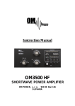
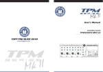
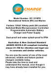
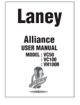
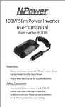
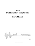
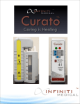
Zide Enterprise Ltd.
483 Allen Drive Delta
BC, Canada V4M 3B9
www.zidecan.com
Tel: (1) 604-948-9496
Fax: (1) 604-948-9491
Quality, Service and Customer Satisfaction
ZD-110/ZD-220 Pump Controller
User Manual
Preface:
Thank you for purchasing the ZD-110 or ZD-220 High Pressure Pump System.
Please go through the whole document before actually installing or operating the
pump system.
The Zide High Pressure Pump System consists of two major parts: Controller and
Pump Unit. These two units connect to each other with signal and power lines. This
Controller is custom made for this Pump Unit, so it will not be suitable to connect
this Controller to a different Pump Unit other than the one that comes with this
Controller.
*** There is a potential hazard if the pump and controller are not properly installed.
Please follow this manual carefully. ***
Page 1 of 19
1. Introduction and Specification:
The Controller is designed to control the output pressure of the pump through a
feedback from a pressure sensor and a built-in timer to control the On/Off time of
the pump unit. The controller is expandable so as to control multiple Pump Units at
once and the add-on Pump unit can be set to control an individual zone (ex: Zone 1).
Thus, you have the freedom to start/stop all zones or manually start/stop a single
zone from the front panel of the Controller Unit.
Down below is the electrical specifications and features of the Controller Unit:
• Input Voltage: AC 110V or 220V (manually select through internal switch)
• Input Frequency: 50 or 60Hz
• Maximum Output Power: 200Watts
• Maximum Pressure Setting: 70 Kg/cm²
• Pressure Display Unit: Kg/cm^2, psi (pound square inch), BAR
• Timer Setting Range: 10 seconds ~ 60 minutes
• Pressure Release Valve output: 0.1Amp
• Water source control valve output: 0.1Amp
Here is the physical environment and operating condition of ZD-110/ZD-220
misting pump system:
• +5 C
̊ and +40 ̊C
• 30% to 95%RH
• Altitude up to 1000m
• Transportation and storage temperatures within a range of -25 ̊C to +55 ̊C, 24h
at up to +70 ̊C
Here is the mass and dimension of ZD-110/ZD-220 misting pump system:
• Control box:
Mass: 1.25Kg Dimension: 225x155x56mm
• Pump system box: Mass: 11.5kg
Dimension: 305x390x125mm
Page 2 of 19
2. Connector
AC power and
Pump and control
Pressure sensor
Communication
fuse socket
valve connector
connector
signal connector
o AC power and fuse socket: AC power source connector; below is the
fuse socket. Please replace with a 3A fuse when needed. If the fuse
breaks right after the AC power switch turns on, please unplug the AC
power cord and phone our distributor for troubleshooting.
o Pump and control valve connector:
Pump +
Pump -
Pressure
Water source
Release Valve
control valve
Pump+/- : connect to Pump motor
Water source control valve : connect to water source control
valve (AC output)
Pressure release valve : connect to pressure release valve (AC
output)
Page 3 of 19
o Pressure sensor connector: Connects to the built-in pressure sensor
for a stable pressure output. This means our pump system will provide
a constant pressure output that is not affected by the number of nozzles
present.
V+
S+
V-
S-
o Communication signal connector: Signal line connects between the
controller and pump unit(s). The maximum distance between the
controller and pump unit is 100 meters.
485+
485-
*** For reference only, this controller will work only with the dedicate
pump unit and pressure sensor ***
Page 4 of 19
3. Function Key and display
The above photo is what your Controller Unit looks like. Please refer to the
detailed explanation/definitions of each key and display below.
Function display (LED):
• PUMP: pump running status. On - the pump is running. Off -the pump is
off. This LED also works with TIMER LED during the timer setting
process. Please see section 4 for more details.
• PRESSURE: when flashing, the controller is in Pressure Setting Mode.
Please see section 4 for detailed steps explaining how to set up the
Pressure Setting Mode.
• TIMER: when flashing, the controller is in Timer Setting Mode. Please
see section 4 for detailed steps explaining how to set up the Timer Setting
Mode.
• Kg/cm²: the number is displayed in Kg/cm² units when this LED is on
• x10 psi: the number is displayed in x10 psi units when this LED is on
• Bar: the number is displayed in Bar units when this LED is on
• Zone 1 ~ 4: On – pump(s) in this zone is in running mode. Off – pump(s)
in this zone is in the ‘off’ mode.
Page 5 of 19
Key and Switch:
• POWER: Main power switch. This switch controls the AC power of both
the controller and pump units.
• SETTING: main function switch; the controller will enter configuration
mode after this key is pressed. Keep pressing this key to toggle through
the different menus, PRESSURE -> TIME ON -> TIME OFF ->
PRESSURE UNIT Display -> PRESSURE -> ……. Controller will go
back to normal mode after an idle 10 seconds.
• ▲ : Up key.
• ▼ : Down key.
• START: starts the pump when this key is pressed. The controller will
move out from configuration mode and start the pump when this key is
pressed.
• STOP: stops the pump from running when this key is pressed. The
controller will move out from configuration mode when this key is
pressed.
• ZONE 1 ~ 4: manually Start/Stop pump(s) running while in these zones.
Page 6 of 19
4. Setting
To force the controller to enter the setting mode, the first step is to press the
‘SETTING’ key. This is the setting sequence when the ‘SETTING’ key is pressed:
Normal Operate Mode
↓ ‘SETTING’ key pressed
Pressure Setting Mode (Pressure LED flash)
↓ ‘SETTING’ key pressed
Pump On Timer Mode (Timer LED flash and Pump LED
On)
↓ ‘SETTING’ key pressed
Pump Off Timer Mode (Timer LED flash)
↓ ‘SETTING’ key pressed
Presser Unit Display Mode (Pressure Unit LED flash)
↓ ‘SETTING’ key pressed
Normal Operate Mode
*** The controller will go back to ‘Normal Operate Mode’ when no key is
pressed for over 10 seconds. ***
The table below shows what the LED displays when the controller is in a different
mode:
Setting
PUMP
Pressure setting
Pump On timer
Steady
Lighted
Led display
PRESSURE
TIMER
Flash
Flash
Pump Off timer
Pressure Unit
selection
Pressure Unit
Flash
Flash
Page 7 of 19
Detail setting procedure for each mode:
Pressure Setting Procedure:
1.
2.
3.
4.
Press ‘SETTING’ key once
Make sure the ‘PRESSURE’ led is flashing
Press ▲ and ▼ key to set the desired pressure.
Press ‘SETTING’ key three times or leave the controller untouched for over
10 seconds when finished.
Pump On/Off Timer Setting Procedure:
1.
2.
3.
4.
5.
6.
7.
Press ‘SETTING’ key twice
Make sure the ‘TIME’ led is flashing and ‘PUMP’ led is shining.
Press ▲ and ▼ key to adjust the value of the Pump On Timer.
Press ‘SETTING’ key once.
Make sure the ‘TIME’ led is flashing and ‘PUMP’ led is off.
Press ▲ and ▼ key to adjust the value of the Pump Off Timer.
Press ‘Setting’ key twice or leave the controller untouched for over 10
seconds when completed.
8. The timer range is between 10 seconds to 60 minutes. Below shows how it
will be displayed (please pay attention to the decimal points on the following
table):
Display
0.1
0.5
1.0
1.5
9.5
10
60
Page 8 of 19
Time value
10 seconds
50 seconds
1 minutes
1 minute 50 seconds
9 minutes 50 seconds
10 minutes
60 minutes
Display Pressure Unit Setting Procedure:
1. Press ‘SETTING’ key three times
2. Make sure one of the pressure units led (Kg/cm², x10 psi or Bar) is flashing
3. Press ▲ and ▼ key to select the pressure unit that will meet your
requirement. The selected pressure will have the led flashed.
4. Press ‘SETTING’ key once or leave the controller untouched for over 10
seconds when finished.
Start/Stop Pump Procedure:
The controller has to be in ‘Normal Operate Mode’ before the following steps will
work.
A. Pump operates according to the timer On/Off setting:
1. Pressing the ‘START’ key on the controller will start the pump in which
the pump operates according to the On/Off timer setting.
2. Pressing the ‘STOP’ key will stop the pump from operating immediately.
B. To operate the pump continuously:
1. Set the time of either ‘Pump On’ timer or ‘Pump Off’ timer to 0.0
2. Press ‘START’ key, the pump will operate continuously.
3. Press ‘STOP’ key, the pump will stop permanently.
C. Zone operating:
This section is only applied when the controller is configured with the
‘ZONE’ mode (P2 and P3 mode, refer to Section 5 for more details)
• The controller is always assigned to ‘Zone 1’. This is the default
behavior and there is no configuration available to move the controller
to different zone.
• The auxiliary pump system can be configured to a different zone other
than Zone 1.
• All zones start operating when ‘START’ key is pressed.
• All zones stop operating when ‘STOP’ key is pressed.
• Pressing specific zone keys will allow it to start or stop operating (the
LED will toggle accordingly); when ‘on’ a light will be shining and if
Page 9 of 19
it is ‘off’, the light will be off. For example: LEDs of Zone 1,3 are on
and LEDs of Zone 2,4 are off; this means that Zone 1 and 3 will
operate according to the controller setting. Zone 2 and 4 will stop
operating.
Page 10 of 19
5. Control Mode
There are 5 different modes for configuring the controller that you can use for
different requirements; here are the instructions of how you can enter the control
mode setting.
How to enter control mode setting:
• Turn off the controller power switch
• Press ‘SETTING’ and ‘STOP’ keys before turning the controller power
back on.
• Press ▲ and ▼ key to select P0 to P4 mode.
• Turn off controller when the desired mode is selected.
• You only need to configure it once. The controller will keep this setting
in its own memory.
Mode
P0
P1
P2
P3
P4
Description
Only one pump, no auxiliary pump
Pressure Display
Main pump output
pressure
Only one pump, no auxiliary pump. Automatically Main pump output
runs after the controller is on, there is no need to
pressure
press the ‘START’ key.
Main pump and auxiliary pump.
Setting pressure
Main pump and auxiliary pump. Automatically
Setting pressure
runs after the controller is on, no need to press the
‘START’ key required.
Auxiliary pump test mode (for installation testing, Auxiliary pump
it can only connect to one auxiliary pump at once. output pressure
The correct Zone will need to be selected for the
controller to communicate with the auxiliary pump
properly)
Pump protection mode:
The controller has built in waterless and over-pressure protection mode; the
controller will stop the pump from operating when one of these two conditions is
met:
Page 11 of 19
• Controller display < 10 Kg/cm² for over 1 minute. (Waterless mode)
• Controller display > setting pressure * 1.25 for over 1 minute.
(Over-pressure mode)
When the controller enters this mode, the pump will stop and the 7 segment
display will flash and display ‘-- --’.
Please shut-down the power of the controller immediately.
Waterless mode -- check the water source connected to the pump unit to make
sure the tubing that connects to the water source has no problems and there is water
coming from the water source.
Over-pressure mode -- make sure the tubing that connects to the pump is not
clogged or blocked and also check the nozzles to make sure they are not clogged. If
the controller keeps entering this mode, please double check the flow rate of the
system and make sure the total flow rate is over 300cc/min.
Page 12 of 19
6. Pump Unit
The following photos show you what the Pump Unit looks like and what has
been included inside the Pump Unit.
External view:
• Pump and Control valves cable – connect to controller
• Pressure Sensor cable – connect to controller
• Pressure Release Valve Output – returns water while pump stops and
Page 13 of 19
Pressure release valve opens.
• Water Source Slip-Lock Connector – water source for the pump unit and
the slip-lock is in 1/4” size. (It is strongly recommended to filter the
water first before connecting the water source to the slip-lock.)
• Air release valve – designed to release the internal air residing in the
pump for initial set up purpose, this valve will be in the closed state once
there is no air residue inside the pump unit.
• Pump Output Slip-Lock Connector – high pressure pump output,
connects the misting line to this slip-lock and the slip lock is 1/4” size.
Page 14 of 19
Internal view:
• 1.2L/min High Pressure pump – the heart of the pump unit, comes with a
carbon brush replaceable feature.
• Cooling Fan – this internal cooling fan is designed to keep the pump
running under a steady temperature to prevent the pump from overheating
during extreme weather condition.
• Pressure Release Valve – the valve is to prevent the nozzle from dripping
when the pump stops.
• Water Source Control Valve – to control the water source when needed to
prevent nozzle dripping/spraying when the pump is not running.
• Pressure sensor – measures the output water pressure constantly and feeds
Page 15 of 19
this information back to the controller to get the accurate pressure out.
Page 16 of 19
7. Remote Control Unit
This Remote Controller is an optional accessory that can be purchased with or
after the Pump Unit. It has the same key set up as the keys on the controller, so you
will have the luxury to control the pump unit quite like how you would control a
normal television.
Down below is the photo of the Remote. The actual dimensions of the remote
controller is 8.5cm x 4cm x 0.3cm (L x W x H):
Note: A & B keys – reserve keys, no functionality are assigned to these two keys.
Page 17 of 19
8. Patent
The ZD-110/ZD-220 has earned the following patents.
Page 18 of 19
9. Certification
Page 19 of 19