Download User Manual E-DriveTM - Mold
Transcript
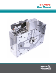
E-Drive
User Manual
TM
Table of Contents
Table of Contents
Section 1 - Introduction...................................................... 1-1
Warranty and Documentation........................................................................................... 1-1
Release Details.................................................................................................................... 1-1
Trademarks and Patents..................................................................................................... 1-2
Section 2 - Global Support................................................. 2-1
Manufacturing Facilities..................................................................................................... 2-1
Regional Offices.................................................................................................................. 2-1
International Representatives............................................................................................ 2-2
Section 3 - Safety................................................................ 3-1
Introduction......................................................................................................................... 3-1
Safety Hazards.................................................................................................................... 3-1
E-Drive Safety Warnings.................................................................................................... 3-4
E-Drive Cautions................................................................................................................. 3-4
Mag-Pin Safety.................................................................................................................... 3-4
Section 4 - Preparation....................................................... 4-1
Introduction......................................................................................................................... 4-1
Screw Lengths.................................................................................................................... 4-1
Tools Required.................................................................................................................... 4-2
Unpacking........................................................................................................................... 4-3
Cleaning............................................................................................................................... 4-3
Establishing Your System Type.......................................................................................... 4-3
Typical E-Drive System...................................................................................................... 4-4
E-Drive Components.......................................................................................................... 4-6
E-Drive User Manual
Not under documentation control if printed. May be revised without notice Electronic version is available at www.moldmasters.com
i
Revision 05
©09-2010
Table of Contents
Section 5 - Assembly........................................................... 5-1
Introduction......................................................................................................................... 5-1
Complete Assembly (3D View)........................................................................................... 5-1
Complete Assembly (Center Section)............................................................................... 5-1
Assembly Summary........................................................................................................... 5-2
Assembly Details................................................................................................................ 5-2
First Time Installation or Replacement of the Belt..........................................................5-14
Checking for Misalignment...............................................................................................5-15
Section 6 - Mag-Pin Option................................................ 6-1
Introduction......................................................................................................................... 6-1
Mag-Pin Assembly (3D View)............................................................................................. 6-1
Mag-Pin Application Cautions........................................................................................... 6-2
Mag-Pin Activation / Deactivation..................................................................................... 6-2
Handling Magnets.............................................................................................................. 6-3
Assembly Summary........................................................................................................... 6-4
Assembly Details................................................................................................................ 6-4
Mag-Pin Extraction............................................................................................................. 6-9
Section 7 - Maintenance..................................................... 7-1
Introduction......................................................................................................................... 7-1
Recommended Maintenance ............................................................................. 7-1
Lubrication of Ball-Screw Assembly................................................................................. 7-1
Inspection of the Timing Belt............................................................................................. 7-1
Replacement of Bearings................................................................................................... 7-1
Assembly / Disassembly of Top Plate................................................................................ 7-2
Index..................................................................................Index-i
E-Drive User Manual
Not under documentation control if printed. May be revised without notice Electronic version is available at www.moldmasters.com
ii
Revision 05
©09-2010
Introduction
Section 1 - Introduction
We would like to take this opportunity to thank you for purchasing a Mold-Masters® E-Drive™system.
The purpose of this manual is to assist users in the integration, operation and maintenance of their
E-Drive system. This manual also provides information related to the Mag-Pin (Magnetic Valve Pin
Holder) option.
Symbols Used in the Manual
GENERAL DESCRIPTION OF SYMBOL
WARNING
Indicates an immediate or potentially hazardous situation, which if not
avoided, could result in a serious injury or death.
CAUTION
Failure to follow instructions may damage equipment
NOTE
Indicates additional information or used as a reminder
Warranty and Documentation
Please check with your original order documentation for warranty details.
NOTE
Please do not return any parts to Mold-Masters without prior pre-authorization and a return authorization number supplied by Mold-Masters (2007) Limited.
Documentation will include one or more of the following:
• Information on the Mold-Masters E-Drive system in general and information on the Mag-Pin
(Magnetic Valve Pin Holder) option.
• Parts list contains all system components. Together with the general assembly drawing, the
parts list should be referenced when ordering spare parts.
• General assembly drawing used to integrate your E-Drive system into the mold.
WARNING
This manual must be used in conjunction with any appropriate Machine, Hot Runner, and
Temperature Controller User Manual.
When ordering this manual, please reference document number: EMMEDUM05.
Release Details
Document #
EMMEDUM05
Release Date
Version
8 September 2010
05
E-Drive User Manual
Not under documentation control if printed. May be revised without notice Electronic version is available at www.moldmasters.com
1-1
Revision 05
©09-2010
Introduction
Trademarks and Patents
ACCU-VALVE, DURA, FLEX-DURA FLEX-SERIES, FUSION-SERIES, HOT EDGE, INJECTIONEERING,
MASTERPROBE, MASTER-SHOT, MOLD-MASTERS, MELT-DISK, MOLD-MASTERS ACADEMY, MASTERSERIES, MASTERSOLUTION, MASTERSPEED, MERLIN, MOLD-MASTERS SYSTEM, SCAN-MASTER,
STACK-LINK, are the registered trademarks of MOLD-MASTERS (2007) LIMITED.
Information contained herein is, to our best knowledge, true and accurate, but all recommendations or
suggestions are made without guarantee. Since the conditions of use are beyond our control, MoldMasters disclaims any liability incurred in connection with the use of our products and information
contained herein. No person is authorized to make any statement or recommendation not contained
herein, and any such statement or recommendation so made shall not bind Mold-Masters. Furthermore, nothing contained herein shall be construed as a recommendation to use any product in conflict
with existing patents covering any products or its use, and no license implied or in fact granted herein
under the claims of any patents.
No part of this publication may be reproduced or transmitted in any form or by any means, electronic
or mechanical, including photocopy, recording, or any information storage and retrieval system without permission in writing from the publisher. All details, standards and specifications may be altered in
accordance with technical development without prior notification.
May be manufactured under one or more of the following U.S. Patents:
5015170, 5030084, 5046942, 5049062, 5061174, 5094603, 5106291, 5118279, 5118280, 5122050, 5125827,
5135377, 5142126, 5148594, 5206040, 5217730, 5223275, 5227596, 5227181, 5235737, 5238378, 5238391,
5268184, 5269676, 5282735, 5284436, 5299928, 5312242, 5326251, 5334008, 5334010, 5346388, 5366369,
5366370, 5387099, 5405258, 5421716, 5427519, 5429491, 5437093, 5441197, 5443381, 5460510, 5474440,
5494433, 5496168, 5507635, 5507636, 5536165, 5591465, 5599567, 5614233, 5641526, 5644835, 5652003,
5658604, 5695793, 5700499, 5704113, 5705202, 5707664, 5720995, 5792493, 5795599, 5820899, 5843361,
5849343, 5853777, 5935615, 5935616, 5935621, 5942257, 5952016, 5980236, 6009616, 6017209, 6030198,
6030202, 6062841, 6074191, 6077067, 6079972, 6095790, 6099780, 6113381, 6135751, 6162043, 6162044,
6176700, 6196826, 6203310, 6230384, 6270711, 6274075, 6286751, 6302680, 6318990, 6323465, 6348171,
6350401, 6394784, 6398537, 6405785, 6440350, 6454558, 6447283, 6488881, 6561789, 6575731, 6625873,
6638053, 6648622, 6655945, 6675055, 6688875, 6701997, 6739863, 6752618, 6755641, 6761557, 6769901,
6776600, 6780003, 6789745, 6830447, 6835060, 6840758, 6852265, 6860732, 6869276, 6884061, 6887418,
6890473, 6893249, 6921257, 6921259, 6936199, 6945767, 6945768, 6955534, 6962492, 6971869, 6988883,
6992269, 7014455, 7018197, 7022278, 7025585, 7025586, 7029269, 7040378, 7044191, 7044728, 7048532,
7086852, 7105123, 7108502, 7108503, 7115226, 7118703, 7118704, 7122145, 7125242, 7125243, 7128566,
7131832, 7131833, 7131834, 7134868, 7137806, 7137807, 7143496, 7156648, 7160100, 7160101, 7165965,
7168941, 7168943, 7172409, 7172411, 7175419, 7175420, 7179081, 7182591, 7182893, 7189071, 7192268,
7192270, 7198740, 7201335, 7210917, 7223092, 7238019, 724418, 7252498, 7255555, 7258536, 7270538,
7303720, 7306454, 7306455, 7314367, 7320588, 7320589, 7320590 7326049, 7344372, 7347684, 7364425,
7364426, 7370417,7377768, 7381050, 7396226, 7407379, 7407380, 7410353, 7410354, 7413432, 7416402,
7438551, 7462030, 7462031, 7462314, 7465165, 7470122, 7507081, 7510392, 7513771, 7513772, 7517214,
7524183, 7527490, 7544056, 7547208, 7553150, 7559760, 7559762, 7565221, 7581944, 7611349, 7614869,
7614872, 7618253, 7658605, 7658606, 7671304, 7678320, 7686603, 7703188, 7713046, 7722351, 7731489,
7753676, D525592, RE38265, RE38396, RE38920, RE39935, RE40478, RE40952 + Pending.
© 2010 MOLD-MASTERS (2007) LIMITED. ALL RIGHTS RESERVED.
E-Drive User Manual
Not under documentation control if printed. May be revised without notice Electronic version is available at www.moldmasters.com
1-2
Revision 05
©09-2010
Global Support
Section 2 - Global Support
Manufacturing Facilities
GLOBAL HEADQUARTERS
CANADA
EUROPEAN HEADQUARTERS
GERMANY / SWITZERLAND
ASIAN HEADQUARTERS
CHINA/HONG KONG/TAIWAN
Mold-Masters Europa GmbH
Postfach/P.O. Box 19 01 45
76503 Baden-Baden, Germany
Neumattring 1
76532 Baden-Baden, Germany
tel: +49 7221 50990
fax: +49 7221 53093
info@moldmasters.de
Mold-Masters (KunShan) Co, Ltd
Zhao Tian Rd
Lu Jia Town, KunShan City
Jiang Su Province
People’s Republic of China
tel: +86 512 86162882
fax: +86 512-86162883
mmc-sales@moldmasters.com
SOUTH AMERICAN
HEADQUARTERS
BRAZIL
INDIA
JAPAN
UNITED KINGDOM
U.S.A.
Mold-Masters Limited
233 Armstrong Avenue
Georgetown, Ontario
Canada L7G 4X5
tel: +1 (905) 877 0185
fax: +1 (905) 873 2818
info@moldmasters.com
Mold-Masters do Brasil Ltda.
Rua Hum, 1106 e 1126 Jd. Manchester - Nova Veneza
Sumarè - São Paulo Brasil
CEP 13178-440
tel: +55 19 3922 4265
fax: +55 19 3922 4266
moldmasters@moldmasters.com.br
Mold-Masters UK /
PMS Systems Ltd
Netherwood Road
Rotherwas
Hereford
HR2 6JU
tel: +44 1432 265768
fax: +44 1432 263782
mmuk-all@moldmasters.co.uk
Mold-Masters Technologies
Private Limited
# 247, Alagesan Road,
Shiv Building, Saibaba Colony.
Coimbatore T. N.
India 641 011
tel: +91 422 423 4888 - 20
fax: +91 422 423 4800
mmtplinfo@moldmasters.com
Mold-Masters K.K.
1-4-17 Kurikidai, Asaoku
Kawasaki, Kanagawa
Japan, 215-0032
tel: +81 44 986 2101
fax: +81 44 986 3145
info@mmkk.co.jp
Mold-Masters Injectioneering LLC
103 Peyerk Court
Romeo, MI 48065
tel: +1 800 450 2270 (USA)
tel: +1 (586) 752-6551
fax: +1 (586) 752 6552
info@moldmasters.com
Regional Offices
AUSTRIA / HUNGARY
CZECH REPUBLIC
FRANCE
KOREA
MEXICO
POLAND
Mold-Masters Handelsges.m.b.H.
Pyhrnstrasse 16
A-4553 Schlierbach
Austria
tel: +43 7582/51877
fax: +43 7582/51877 18
office@moldmasters.at
Mold-Masters Korea Ltd
No.1210, Byucksan Digital Valley 5
Cha,
60-73 Gasan-dong, Geumcheon-gu,
Seoul,153-788,South Korea
Tel:+82 2 2082 4755
Fax:+82 2 2082 4756
mmkr-sales@moldmasters.com
Mold-Masters Europa GmbH
Hlavni 823
75654 Zubri
Czech Republic
tel: +420 571 619 017
fax: +420 571 619 018
cz@moldmasters.eu
Mold-Masters France
ZI la Marinière,
2 Rue Bernard Palissy
91070 Bondoufle
tel: +33 1 82 05 00 80
fax: +33 1 82 05 00 83
mmf-info@moldmasters.eu
MM Hot Runner Injection México, S.A.
de C.V.
Av. San Carlos No. 4 - Nave 2
Parque Industrial Lerma
Lerma, Estado de México
52000, México
Tel: +52 728 282 48 33
Fax: +52 728 282 47 77
mexico@moldmasters.com
E-Drive User Manual
Mold-Masters Europa GmbH
Skr. Pocztowa 59
00-908 Warszawa
Poland
tel: +48 (0) 66 91 80 888
fax: +48 (0) 66 91 80 208
pl@moldmasters.eu
Not under documentation control if printed. May be revised without notice Electronic version is available at www.moldmasters.com
2-1
Revision 05
©09-2010
Global Support
Regional Offices - Con't
SINGAPORE / MALAYSIA
INDONESIA / THAILAND
Mold-Masters Singapore PTE. Ltd.
No 48 Toh Guan Road East
#06-140 Enterprise Hub
Singapore 608586
Republic of Singapore
tel: +65 6261 7793
fax: +65 6261 8378
mmsinfo@moldmasters.com
SPAIN
Mold-Masters España
Serennia Business Center
Buenos Aires 37-29
08902 Hospitalet de Llobregat
Barcelona, Spain
tel: +34 93 802 36 01
fax: +34 93 802 49 08
spain@moldmasters.eu
International Representatives
Argentina
Australia
Bulgaria
Denmark, Norway, Sweden
Finland
Hong Kong
Israel
Italy
Portugal
Romania
Turkey
Vietnam
Sollwert S.R.L.
La Pampa 2849 2∫ B
C1428EAY Buenos Aires
Argentinia
tel: +54 11 4786 5978
fax: +54 11 4786 5978 Ext. 35
sollwert@fibertel.com.ar
H. & G. Englmayer A/S
Skenkelsoevej 9, Postbox 35
DK - 3650 Oelstykke, Denmark
tel: +45 46 733847
fax: +45 46 733859
support@englmayer.dk
ASAF INDUSTRIES Ltd.
29 Habanai Street
PO Box 5598 Holon 58154
Israel
tel: +972 3 5581290
fax: +972 3 5581293
sales@asaf.com
International Mold Trade Co. SRL
Str. Constantin Aricescu, Nr. 21
Bl. 20, Sc. 2, Apt. 20
Bucharest - Sector 1, Romania
tel: +4 021 230 60 51
fax : +4 021 231 78 43
contact@matritehightech.ro
Comtec I P E
1084 South Road,
Edwardstown, South Australia 5039
PO Box 338, Magill,
South Australia 5072
tel: +61 8 8374 4633
fax: +61 8 8299 0892
bparrington@comtecipe.com
Oy Scalar Ltd.
Viertolantie 12
11120 Riihimaki, Finland
tel: +358 19 783 191
fax: +358 19 783 190
info@scalar.fi
Nicko International Ltd.
Rm 1203, Chevalier Commercial Centre
8 Wang Hoi Road,
Kowloon Bay, Hong Kong
tel: +852 2755 2783
fax: +852 2798 8656
sales@nicko.com.hk
Commerciale Isola SPA
Via G.B. Tiepolo 3
35010 Cadoneghe, (Padova), Italy
tel: +39 49 706600
fax: +39 49 8874231
info@com-isola.it
Gecim LDA
Rua Fonte Dos Ingleses, No 2
Engenho
2430-130 Marinha Grande, Portugal
tel: +351 244 575600
fax: +351 244 575601
gecim@gecim.pt
MMG Consulting & Engineering
Yesil Çesme Sok No:30/3
Çiftehavuzlar 81060, Istanbul, Turkey
tel: +90 216 357 0783
fax: +90 216 385 0656
mustafa.gevrek
@mmgmuhendislik.com
E-Drive User Manual
Mold-Trade OOD
62, Aleksandrovska St.
Ruse City
Bulgaria
tel: +359 82 821 054
fax: +359 82 821 054
contact@mold-trade.com
Lotus Chemical Technology
393 Dien Bien Phu St., Ward 4, Dist. 3,
HoChiMinh City, Vietnam
tel: +84 8 832 7605,
fax: +84 8 832 7730
dieuphuoc.nguyen@lotusfirma.com
Not under documentation control if printed. May be revised without notice Electronic version is available at www.moldmasters.com
2-2
Revision 05
©09-2010
Safety
Section 3 - Safety
Introduction
Any instructional material provided by Mold-Masters for the operation and maintenance of equipment,
does not in any way absolve the employer from fulfilling the following obligations and Mold-Masters disclaims liability for injury to personnel using equipment supplied.
It is the responsibility of the employer to:
• Ensure the original and continuing competence of personnel caring for, setting up, inspecting and
maintaining injection molding equipment.
• Establish and follow a program of periodic and regular inspections of injection molding equipment to
ensure they are in safe operating condition and proper adjustment.
• Ensure that no modifications, repairs, or rebuild of portions are made to the equipment that reduces
the level of safety existing at time of manufacture or remanufacture.
Safety Hazards
The following safety hazards are most commonly associated with plastic injection molding equipment
(From the American National Standard for Plastics Machinery Horizontal Injection Molding Machines-ANSI/
SPI B151.1- 2007).
WARNING
For Safety Information also refer to all machine manuals and local regulations and codes.
2
(1) Mold area
10
5
3
(2) Clamping mechanism area
(3) Area of movement of core and ejector
drive mechanisms outside areas 1& 2
(4) Nozzle area
(5) Plasticizing and or injection unit area
(6) Feed opening area
Top View with Guards Removed
(7) Area of the heater bands of the plasticizing and/or injection cylinders
9
1
2
(8) Parts discharge area
5
4
6
7
(9) Hoses
(10) Area inside the guards and outside the
mold area
8
• Figure 3-1: Injection molding machine (HIMM) with
horizontal clamping unit and horizontal injection unit,
shown without guards for illustration clarity.
Front View with Guards Removed
E-Drive User Manual
Not under documentation control if printed. May be revised without notice Electronic version is available at www.moldmasters.com
3-1
Revision 05
©09-2010
9
Safety
Hazard Area
Potential Hazards
Mold Area
Mechanical Hazards
Area between the plat- Crushing and/or shearing and/or impact hazards caused by:
• Movement of the platen Movements of the injection barrel(s) into the mold
ens.
area Movements of cores and ejectors and their drive mechanisms.
See Figure 3-1 item 1
• Tie bar motion.
Thermal Hazards
• Burns and/or scalds due to operating temperature of:
• The mold heating elements of the molds.
• Plasticized material released from/through the mold.
Clamping Mechanism
Area
See Figure 3-1 area 2
Mechanical Hazards
Crushing and/or shearing and/or impact hazards caused by:
• Movement of the platen.
• Movement of the drive mechanism of the platen.
• Movement of the core and ejector drive mechanism.
Movement of drive
mechanisms outside
the mold area and
outside the clamping
mechanism area.
See Figure 3-1 area 3
Mechanical Hazards
Mechanical hazards of crushing, shearing and/or impact caused by the movements of:
• Core and ejector drive mechanisms.
Nozzle area
Mechanical Hazards
The nozzle area is the Crushing, shearing hazards, and/or impact hazards caused by:
area between the bar- • Forward movement of the plasticizing and/or injection unit including
rel and the sprue bushnozzle.
ing.
• Movements of parts of-the power operated nozzle shutoff and their drives.
See Figure 3-1 area 4
• Over pressurization in the nozzle.
Thermal Hazards
Burns and or scalds due to operating temperature of:
• The nozzle.
• Plasticized material discharging from the nozzle.
Plasticizing and/or
injection unit area
Area from the adaptor/barrelhead/end
cap to the extruder
motor above the sled
including the carriage
cylinders.
See Figure 3-1 area 5
Mechanical Hazards
Crushing, shearing and/or drawn into hazards caused by:
• Unintentional gravity movements e.g. for machines with plasticizing and/or
injection unit positioned above the mold area.
• The movements of the screw and/or the injection plunger in the cylinder
accessible through the feed opening.
• Movement of the carriage unit.
Thermal Hazards
Burns and or scalds due to operating temperature of:
• The plasticizing and/or injection unit.
• The heating elements e.g. heater bands.
• The plasticized material and/or vapors discharging from the vent opening,
feed throat or hopper.
Mechanical and/or Thermal Hazard
Hazards due to reduction in mechanical strength of the plasticizing and/or
injection cylinder due to overheating.
E-Drive User Manual
Not under documentation control if printed. May be revised without notice Electronic version is available at www.moldmasters.com
3-2
Revision 05
©09-2010
Safety
Hazard Area
Potential Hazards
Feed Opening
See Figure 3-1 area 6
Pinching and crushing between injection screw movement and housing.
Area of the heater Burns and or scalds due to operating temperature of:
bands of the plasticiz- • The plasticizing and/or injection unit.
ing and/or injection • The heating elements e.g. heater bands.
• The plasticized material and/or vapors discharging from the vent opening,
cylinders
feed throat or hopper.
See Figure 3-1 area 7
Parts Discharge Area
See Figure 3-1 area 8
Mechanical Hazards
Accessible Through the Discharge Area
Crushing, shearing and/or impact hazards caused by:
• Closing movement of the platen Movements of cores and ejectors and their
drive mechanisms.
Thermal Hazards
Accessible Through the Discharge Area
Burns and or scalds due to operating temperature of:
• The mold.
• Heating elements of the mold.
• Plasticized material released from/through the mold.
Hoses
See Figure 3-1 area 9
• Whipping action caused by hose assembly failure.
• Possible release of fluid under pressure that can cause injury.
• Thermal hazards associated with hot fluid.
Area Inside the Guards Crushing and/or shearing and/or impact hazards caused by:
and Outside the Mold • Movement of the platen.
Area
• Movement of the drive mechanism of the platen.
See Figure 3-1 area 10 • Movement of the core and ejector drive mechanism.
• Clamp opening movement.
Electrical Hazards
• Electric shock or burns due to contact with live conductive parts.
• Electrical or electromagnetic disturbance generated by the motor control
unit.
• Electrical or electromagnetic disturbance that can cause failures in the
machine control systems and adjacent machine controls.
• Electrical or electromagnetic disturbance generated by the motor control
unit.
Hydraulic
Accumulators
High pressure discharge.
Power Operated Gate
Crush or impact hazards caused by the movement of the power operated
gates.
Vapors and Gases
Certain processing conditions and or resins can cause hazardous fumes or
vapors.
E-Drive User Manual
Not under documentation control if printed. May be revised without notice Electronic version is available at www.moldmasters.com
3-3
Revision 05
©09-2010
Safety
E-Drive Safety Warnings
Never touch or inspect the timing belt when power is on and E-Drive motor and controller are connected. Unplug the controller before any maintenance.
Do not operate the equipment with unconfined long hair, loose clothing or jewellry, including name
badges, neckties, etc. These may get caught by the moving belt mechanism and can cause death or
serious injury.
Always cover belt area with proper protecting sheet before any bench test or in-mold testing.
High Voltage and amperage cables are connected to E-drive controller (220VAC). Also there is high
voltage cable connection between servo motor and controller.
Unplug the controller before performing any maintenance work.
E-Drive Cautions
Make sure the controller power supply is unplugged (or turned off) before plugging in the cables of
the motor. Otherwise it can cause damage to the motor (do not "hot-plug" the motor!).
Carefully read the instructions before operating the equipment. If in doubt, contact Mold-Masters
for clarification.
E-Drive components are rated to operate at temperatures less than 70ºC (158ºF). Do not heat the hot
runner system without connecting a proper cooling system. In addition, if in your application mold
temperature needs to be set above 70ºC (158ºF), use proper mold design for high temperatures. In
high temperature applications, an additional insulation plate and support plate need to be installed
above the manifold plate (See E-Drive Catalogue Pages). In addition, plates above manifold plate
need to be cooled with separate cooling line set at lower temperatures (recommended temperature
is below 50ºC).
Mag-Pin Safety
WARNING
When the E-Drive system is equipped with a magnetic valve pin holder in the synchro-plate it is
equipped with very strong magnets. Be careful of potential pinch hazards when handling the magnets.
CAUTION
Assembly of the magnetic valve pin holder parts must be done in a clean area that is free of metal
chips. Ensure parts are clean of metal before assembly.
Do not place the magnets close to other magnets or other ferromagnetic parts. Their light weight
and high magnetic strength can cause a powerful collision force that may cause the magnet to chip
or break due to impact.
E-Drive User Manual
Not under documentation control if printed. May be revised without notice Electronic version is available at www.moldmasters.com
3-4
Revision 05
©09-2010
Preparation
Section 4 - Preparation
Introduction
The following section is a step-by-step guide to preparing your Mold-Masters E-Drive system
for use.
Screw Lengths
WARNING
The use of an incorrect size, length and grade screw could cause the screw to shear, fatigue or stretch beyond its yield point, resulting in expensive downtime of the hot runner.
Be aware of warnings placed on the assembly drawings. When the manifold is heated the metal expands
stretching the mounting screws, if screw lengths are shortened there is a possibility of shearing.
The expansion factor is calculated into the length of each screw size.
WARNING
DO NOT SHORTEN SCREW
S.H.C.S. M12 X 130
(ISO-GRADE 12.90
OR ½ - 13 X 4.75
(ASTM A574)
NOT SUPPLIED BY
MOLD-MASTERS
E
L
P
M
A
EX
E-Drive User Manual
Not under documentation control if printed. May be revised without notice Electronic version is available at www.moldmasters.com
4-1
Revision 05
©09-2010
Preparation
Tools Required
Depending on the size and complexity of your hot runner system, you will require most of the tools and
materials listed below.
•
Allen keys - Set of imperial size keys and metric sizes 4, 5, 6, 8 and 10 mm for use on both imperial and metric cap screws (depending on system)
•
Anti-seize compound - To prevent oxidation of screw threads that could cause screws to seize with high temperatures
•
Solvents (denatured alcohol) - For removal of rust inhibitors
•
Calibrated torque wrench - For consistent screw pressure throughout the system
•
Pliers - For general assembly work
•
Circlip pliers - To remove and install Circlip in valve systems
•
Micrometer - (sizes 0 - 6” and 0 - 150 mm) To check system part and plate thickness
•
Depth micrometer - To check bore depths
•
Slot head screw driver - Used in installing thermocouples and ground wires
•
Slot head screw driver (small) - Used in fastening electrical wires to connectors
•
Crimping tool - For fastening connector pins when necessary
•
Wire strippers - For preparing wires
•
Utility knife - For cutting tape, wires etc.
•
Glass tape - Used for grouping wires into zones
•
Bluing Compound - For checking face contact
•
Sockets
•
Lapping compound for valve gate systems
•
Plastic face hammer
•
Valve pin pulling tool
•
Long M5 hex key with T-handle and snap ring in tip (Mold-Masters item number: KEY-BPHEXTKEY5.0)
•
Grease: Castrol Longtime PD2 (Mold-Masters part number: 104L1105I)
•
Proper Valve Pin extraction tools
E-Drive User Manual
Not under documentation control if printed. May be revised without notice Electronic version is available at www.moldmasters.com
4-2
Revision 05
©09-2010
Preparation
Unpacking
1. Carefully remove all components from the shipping box and check that all components listed on the parts
list were supplied.
2. Check that all mold base dimensions are correct and correspond to Mold-Masters general
assembly drawings.
Cleaning
All nozzles, manifolds and hot runner components must be free of the rust inhibitor applied at the factory.
1. Disassemble the system.
2. Wipe down nozzle body.
3. Remove the part and wipe clean.
4. If necessary, use a cotton swab to clean narrow interior surfaces or screw threads. For larger surfaces,
such as mold plates use thinner in spray form to clean channels and recesses.
Establishing Your System Type
The following pages are to be used as a general guide to assist in identifying components. Refer to your general assembly drawings for specific component lists.
E-Drive User Manual
Not under documentation control if printed. May be revised without notice Electronic version is available at www.moldmasters.com
4-3
Revision 05
©09-2010
Preparation
Typical E-Drive System
Insulation Plate
Locating Ring
Top Plate
Servo Motor
Interface Plate
Tensioning Screw
& Lock Nut
Gear Head
Idler Pulley
-without teeth (2)
Drive and
Tensioning Pulley
Ball-Screw
Pulley (2)
Timing Belt
Tensioning Idler
Pulley
Tensioning Idler
Screw
E-Drive User Manual
Not under documentation control if printed. May be revised without notice Electronic version is available at www.moldmasters.com
4-4
Revision 05
©09-2010
Preparation
Synchro-Plate
Inlet Extension
Tensioning Idler
Assembly
Synchro-Plate
Valve Pin Holder
Ball-Screw
Assembly
Valve Pin
Synchro-Plate
Guiding
E-Drive User Manual
Not under documentation control if printed. May be revised without notice Electronic version is available at www.moldmasters.com
4-5
Revision 05
©09-2010
Preparation
E-Drive Components
Ball-Screw Assembly
Tensioning Idler
Assembly
E-Drive Motor Mount - exploded view
Fix Idler (without
teeth)
E-Drive User Manual
Not under documentation control if printed. May be revised without notice Electronic version is available at www.moldmasters.com
4-6
Revision 05
©09-2010
Assembly
Section 5 - Assembly
Introduction
Your Mold-Masters E-Drive system is shipped pre-assembled and requires minimal pre-installation assembly.
The following details the assembly/installation procedures for various components of the E-Drive.
Complete Assembly (3D View)
Complete Assembly (Center Section)
Optional Custom
Clamp Plate Shown
Ballscrew
Fixed Bearing
(Angular Contact Bar
Bearing)
Floating Bearing
(Ball Bearing)
E-Drive User Manual
Not under documentation control if printed. May be revised without notice Electronic version is available at www.moldmasters.com
5-1
Revision 05
©09-2010
Assembly
Assembly Summary
1. Assemble the hot runner system.
2. Assemble the hot runner system to manifold plate.
3. Assemble the interface plate.
4. Assemble the synchro-plate.
5. Drop the synchro-plate to place.
6. Assemble the valve pin holders.
7. Assemble all top plate items (ball-screw assembly needs to be filled with proper grease before shipping, see
"Lubrication of Ball-Screw Assembly").
8. Prepare top plate assembly before lowering.
9. Attach the synchro-plate to top plate assembly.
10. Tighten the belt (if first time installation of belt or replacing belt, refer to “replace The Belt Or First Time
Installation of the Belt”).
11. Inspect parallelism of the synchro-plate.
12. Assemble the special clamping plate (if exists).
13. Assemble the insulation plate & locating ring.
14. E-Drive controller checks.
15. Preparation for shipping.
Assembly Details
1. Assemble the hot runner system.
E-Drive User Manual
Not under documentation control if printed. May be revised without notice Electronic version is available at www.moldmasters.com
5-2
Revision 05
©09-2010
Assembly
2.
Assemble the hot runner system to manifold plate.
3.
Assemble the interface plate:
•
Main leader pins.
•
Synchro-plate leader pins.
•
Bearing and retainers.
•
Fastening screws between plates.
E-Drive User Manual
Not under documentation control if printed. May be revised without notice Electronic version is available at www.moldmasters.com
5-3
Revision 05
©09-2010
Assembly
4.
Assemble the synchro-plate (without ball-nut).
Top stop buttons
(if needed)
Ball-nut flange
seating area
Guide bushings with
top/bottom retainers
Bottom stop buttons
5.
Drop the synchro-plate into place.
Check for smooth up/down
movement of synchro-plate
E-Drive User Manual
Not under documentation control if printed. May be revised without notice Electronic version is available at www.moldmasters.com
5-4
Revision 05
©09-2010
Assembly
6.
Assemble the valve pin holders.
Valve pin holders
7.
Assemble all top plate items (details follow).
Assemble the ball-screw assemblies, pulley
assemblies, motor mount assembly, guide
bushes and belt (release tension from belt).
Flange Nut
E-Drive User Manual
Not under documentation control if printed. May be revised without notice Electronic version is available at www.moldmasters.com
5-5
Revision 05
©09-2010
Assembly
7.1
Prepare the ball-screw.
7.1.1 Assemble the ball-screw and fixed bearing.
7.1.2 T
orque the ball-screw nut (M20 x 1.0) to 19Nm (14
Ft-lb).
7.1.3 M
ake sure the bearing is seating properly in
place.
7.2 Assemble the ball-screw to the top plate.
7.2.1 C
heck dimension of fixed bearing bores in
top plate before assembly.
7.2.2 Insert the ball-screw and fixed bearing into
top plate (press-fit). Bearing will protrude
0.10mm to get loaded by the cover.
E-Drive User Manual
Not under documentation control if printed. May be revised without notice Electronic version is available at www.moldmasters.com
5-6
Revision 05
©09-2010
Assembly
7.3
Fasten cover plate into position.
7.4
Assemble ball-nut on ball-screw.
7.4.1 N
ote: do not disassemble the
arbor from ball-nut before
getting ready for assembling it into
the ball-screw.
7.4.2 B
all-screw mounting kit is
standardized as EDRIVEBSMNTKITP and is supplied with the
system.
ote: arbor needs to be placed
N
properly against ball-screw when
rotating the ball-screw. Failure to
do so may result in balls falling out
of assembly. It would be very
difficult to reassemble the balls
and unit may have to be scrapped.
7.4.4 K
eep the arbor and rubber rings in
a safe place. You will need them
for disassembly of the ball-screw
from ball-nut.
E-Drive User Manual
Not under documentation control if printed. May be revised without notice Electronic version is available at www.moldmasters.com
5-7
Revision 05
©09-2010
Assembly
7.5
Assemble ball-screw and ball-nut.
7.5.1 The nut is to be mounted as follows:
Remove the rubber ring from one end of the
mounting arbor.
Push the mounting arbor with nut until it bears
against the end of the thread. The arbor must
make contact with no axial clearance.
7.5.2 C
arefully turn the nut unit onto the thread, applying only slight thrust.
7.5.3 R
emove the arbor only when the nut unit is
fully located on the screw thread.
7.6
Release the tension of the belt.
7.6.1 L
oosen motor mount screws (just to be able to
slide it).
7.6.2 Release the locknut on tensioning screw.
7.6.3 R
otate the tensioning screw clockwise to
loosen the belt.
Motor mount screws
Tensioning screw &
lock nut
E-Drive User Manual
Not under documentation control if printed. May be revised without notice Electronic version is available at www.moldmasters.com
5-8
Revision 05
©09-2010
Assembly
8.
Prepare top plate assembly before lowering.
8.1 Belt should be loose / tension free.
8.2 B
oth flange-nuts should be at proper
orientation and same level before top-plate is lowered
down for assembly.
Gauge Block
9.
Attach the synchro-plate to top plate assembly.
Using tool KEY-BPHEXTKEY5.0, place the M6 screws
that connect the ball-nut flange to the synchro-plate
and then slightly tighten them. Use another hex key
tool with stronger tip to fully tighten the screws.
Tighten 12 screws evenly in both
sides (Note: belt must be without
tension)
Tool KEY-BPHEXTKEY5.0
E-Drive User Manual
Not under documentation control if printed. May be revised without notice Electronic version is available at www.moldmasters.com
5-9
Revision 05
©09-2010
Assembly
9.1
ith the belt still loose, evenly rotate both ball-screws clockwise until the
W
synchro-plate hits the top stop buttons and is level on each side.
Evenly rotate both
ball-screws clockwise
(Belt is still loose)
10.
Tighten the belt.
10.1 L
oosen motor mount screws (just to be
able to slide them).
10.2 R
elease the locknut on the tensioning
screw.
10.3 R
otate the tensioning screw Counterclockwise to tighten the belt.
10.4 Tighten the motor mount screws.
Motor mount screws
Tensioning screw &
locknut
E-Drive User Manual
Not under documentation control if printed. May be revised without notice Electronic version is available at www.moldmasters.com
5-10
Revision 05
©09-2010
Assembly
11. Inspect parallelism of the synchro-plate.
If holes for inspection of synchro-plate are provided, check parallelism of the synchro-plate with proper
depth gauge tools.
Enlarged view
Inspection holes
12.
Assemble the special clamping plate (optional).
E-Drive User Manual
Not under documentation control if printed. May be revised without notice Electronic version is available at www.moldmasters.com
5-11
Revision 05
©09-2010
Assembly
13.
Assemble the insulation plate and locating ring.
14.
Perform E-Drive Controller Checks.
Before startup of the system, read "E-Drive Controller Operating Manual".
CAUTION
Do not swap E-Drive Controllers for different E-Drive systems without checking manual as
controller setup must match mechanical system.
14.1 C
heck MODE OF OPERATION (See E-Drive Controller Operating Manual).
• If E-Drive system is designed to have the synchro-plate bottoming at a hard stop
at close position of valve pins, E-Drive controller mode of operation should be
"EndStop Mode".
• If E-Drive system is designed to have the valve pins closing position set within a
certain range (usually +/- 0.3mm), E-Drive controller mode of operation should be
"RefPinPosition Mode".
E-Drive User Manual
Not under documentation control if printed. May be revised without notice Electronic version is available at www.moldmasters.com
5-12
Revision 05
©09-2010
Assembly
14.2 C
heck MECHANICAL FACTOR (See E-Drive Controller
Operating Manual).
• If Ball-screw assembly package name is
"EDRIVEBSASM01", then Mechanical Gearing Factor
needs to be set to 1.0 (hint: In such cases, shown
diameter of the top pulley is D=62mm or 2.45").
• If Ball-screw assembly package name is
"EDRIVEBSASM02", then Mechanical Gearing Factor
needs to be set to 1.2 (hint: In such cases, shown
diameter of the top pulley is D=75mm or 2.95")
15.
The hot half is now ready to be installed into the mold.
NOTE
Make sure the synchro-plate valve pins are at the open position
before shipping.
E-Drive User Manual
Not under documentation control if printed. May be revised without notice Electronic version is available at www.moldmasters.com
5-13
Revision 05
©09-2010
Assembly
First Time Installation or Replacement of the Belt
1. If system is new and no plastic is inside, move
the synchro-plate to home position (fully open
position). With proper hex keys on top of
ball-screws, rotate clockwise. If system has
run plastic before, make sure you heat up the
system before moving the synchro-plate to fully
open position. In such case, attach cooling lines
to cooling system and make sure that MoldTemperature will not exceed 70ºC (158ºF) for
E-Drive plates.
7. Install the taper bushing allowing the pulley to
still rotate (not gripping yet).
8. Apply slight tension to engage two pulleys
(check elevation of pulleys).
9. Time both ball-screw pulleys to engage in same
way.
10. Tighten the taper bushing set screws on top of
ball-screw pulleys (make sure the pulleys are at
proper elevation and synchro-plate remains flat
and seated).
2. Remove tension from belt completely from both
sides (motor mount & tensioning idler).
11. Apply proper tension to belt.
3. Loosen nuts above one idler without teeth and
remove the idler pulley (to allow inserting the
belt in tight-belt conditions).
12. Tighten the motor mount screws.
13. Tighten the locknut on tensioning pulley.
14. Check belt height all around and make sure it is
in middle of all pulleys and not rubbing on sides
(measure depth of belt at various places, and
check alignments).
4. Remove the taper bushing set screws on top
of both ball-screw pulleys (1/4-20 UNC).
NOTE: use another standard ¼-20 socket head
cap screw to jack the pulley until it releases (make sure synchro-plate remains all the way
up and seated flat).
15. If possible, while system is heated, do a few
dry cycles (using 24 VDC manual trigger) and
check movement and noise. Double check the
position of belt within all pulleys. See E-Drive
Controller Operating Manual.
5. Replace the belt.
6. Put back the idler without teeth and tighten the
nuts.
Idler tensioning screw
Tensioning idler screws
Taper bushing screws
Use standard 1/4 - 20 socket
head cap screw to jack taper
lock
Idler nut & pulley
(without teeth)
Motor mount screws
Tensioning screw &
locknut
E-Drive User Manual
Not under documentation control if printed. May be revised without notice Electronic version is available at www.moldmasters.com
5-14
Revision 05
©09-2010
Assembly
Checking for Misalignment
1. D
uring belt installation and drive alignment,
two types of misalignment can occur:
• Parallel misalignment - is when driveR
and driveN shafts are parallel, but the
two pulleys lie in different planes.
• Angular misalignment - is when the two
shafts are not parallel.
2. A fleeting angle is the angle at which the belt
enters and exits the pulleys, and equals the sum
of the parallel and angular misalignments.
3. Any degree of pulley misalignment will result
in some reduction of belt life, which is not accounted for in the normal drive design procedure. Misalignment of all positive belt drives
should not exceed 1/4˚ or 5 mm per metre of
centre distance.
4. Misalignment should be checked with a good
straight edge tool. The tool should be applied
from driveR to driveN and from driveN to
driveR so that the effect of parallel and angular
misalignment is taken into account.
Parallel Misalignment
fleeting angle
driveR
driveN
Angular Misalignment
fleeting angle
driveR
driveN
E-Drive User Manual
Not under documentation control if printed. May be revised without notice Electronic version is available at www.moldmasters.com
5-15
Revision 05
©09-2010
Magnetic Valve Pin Option
Section 6 - Mag-Pin Option
Introduction
The following provides details for the assembly/installation of the Mag-Pin (magnetic valve pin holder) which is
an optional component of the E-Drive. This mechanism allows the deactivation of any individual valve pin in the
synchro-plate design at press (without need to open up mold plates). A deactivated valve pin will remain at the
closed position. This provides the ability to selectively shut down any cavity in a synchro-plate design.
Mag-Pin Assembly (3D View)
NUTLM12F-01
(locking nut)
VPMAGHOLDER01
(Adjustable magnet
holder)
VPMAGNET01
(magnet)
PN0R2-017
(O-ring for dust
protection)
SHCSM5X15 (recommended
screws for attachment to
synchro-plate)
VPMAGHOUSING01
(main holder body)
VPHOLDER12
(Valve pin Holder)
Valve pin
(STD 2.5 or 3 mm)
E-Drive User Manual
Not under documentation control if printed. May be revised without notice Electronic version is available at www.moldmasters.com
6-1
Revision 05
©09-2010
Magnetic Valve Pin Option
Mag-Pin Application Cautions
This product is not suitable for all material and hot runner applications. Please contact Mold-Masters regarding
your application.
Factors that need to be considered are:
•
•
•
•
Plastic material.
Nozzle length.
Valve pin size (only for 2.5 and 3 mm diameter valve pins).
Gating style
The following conditions are not recommended for Mag-Pin application:
• Molding very soft and elastic materials with Durometer Hardness (Style A) less than 90 (especially for very
short length nozzles).
• Molding very viscous materials with very long nozzles.
• Accu-Valve CX gating style.
Mag-Pin Activation / Deactivation
Regular operation: Nozzle is at processing temperature and gate is active. Force of magnet is high enough to
hold the valve pin attached to synchro-plate during opening cycle.
Deactivated gate: Nozzle is turned off and colder plastic all around valve pin holds the pin at close position.
Therefore, valve pin can be detached from synchro-plate at magnet interface.
SynchroPlate
Open Position
(Activated Gate)
(8mm Stroke shown)
Close Position
(Both Activated & Deactivated
conditions)
E-Drive User Manual
Open Position
(Deactivated Gate)
(8mm Stroke shown)
Not under documentation control if printed. May be revised without notice Electronic version is available at www.moldmasters.com
6-2
Revision 05
©09-2010
Magnetic Valve Pin Option
Deactivation: After turning the
nozzle Off (for 5 to 10 minutes,
depending on material), plastic
material around valve pin holds
the pin in place and decoupling
happens at magnet interface.
Activation: After turning the
nozzle On (for 4 to 8 minutes,
depending on material), plastic material around valve pin
releases the pin and magnet
gets engaged at interface once
actuation starts.
Deactivated
Activated
Gate
Gate
Open Position
Close Position
Handling Magnets
1. Use supplied plastic spacers (MM
Part # WASHER37) between magnets to prevent them from colliding with each other while handling
and storing.
2. In addition, keep groups of magnets in a thick plastic container to
avoid impact with other parts or
tools.
Plastic Spacer
(WASHER37)
Magnet
WARNING
Be careful of potential pinch hazards when handling the magnets.
E-Drive User Manual
Not under documentation control if printed. May be revised without notice Electronic version is available at www.moldmasters.com
6-3
Revision 05
©09-2010
Magnetic Valve Pin Option
Assembly Summary
1. Place the magnet on top of the valve pin holder.
2. Make sure magnet holder is clean.
3. Place the magnet holder on top of the assembly.
4. Detach the valve pin holder from the magnet holder (slide to side).
5. Place the magnet holder and magnet into the housing.
6. Assemble the nut and lock magnet holder.
7. Lubricate O-ring with a thin layer of high temperature grease and place it into the related groove on the
valve pin holder. Clean excessive grease from top and side faces..
8. Place the valve pin into valve pin holder slot and then gently place the assembly into the housing assembly. Avoid impact forces on magnet.
9. The Mag-Pin is now ready for assembly into the synchro-plate. Heat up the system and complete final
valve pin height adjustment if valve pin protrusion is not correct.
Assembly Details
WARNING
Be careful of potential pinch hazards when handling the magnets.
1.
Place the magnet on top of the valve pin holder.
CAUTION
o not start the assembly in a workbench
D
with lots of metal chips and grinding
powder. Assembly must be done on a clean
workbench. Always use new and clean rags
with no metal chips to clean the parts before
assembly.
Handle the magnets in a safe and thick
plastic container.
Do not place the magnets close to a
ferromagnetic part or close to another
magnet. Their light weight and high
magnetic strength can cause a powerful
collision force that may cause the magnet
faces to chip or even break due to impact.
E-Drive User Manual
Not under documentation control if printed. May be revised without notice Electronic version is available at www.moldmasters.com
6-4
Revision 05
©09-2010
Magnetic Valve Pin Option
2.
Make sure magnet holder (VPMAGHOLDER01) is clean with
smooth surface finish at the interface with the magnet.
3.
Place the magnet holder on top of the assembly.
CAUTION
Make sure the surface of the magnet is clean with no oil
or grease. This will allow easy assembly of magnet into
magnet holder.
E-Drive User Manual
Not under documentation control if printed. May be revised without notice Electronic version is available at www.moldmasters.com
6-5
Revision 05
©09-2010
Magnetic Valve Pin Option
4.
5.
Detach the valve pin holder from the magnet holder (slide to the side).
Place the magnet holder and magnet into housing (VPMAGHOUSING01).
Rotate the magnet holder counter-clockwise with a 5mm hex key until threaded portion
protrudes.
E-Drive User Manual
Not under documentation control if printed. May be revised without notice Electronic version is available at www.moldmasters.com
6-6
Revision 05
©09-2010
Magnetic Valve Pin Option
6.
Assemble the nut and lock magnet holder.
6.1 A
ssemble the jam nut M12-1.00 (NUTLM12F-01) as shown. Note: pitch of thread is
1.00mm per turn.
0.50mm
6.2 A
djust the heights to have 0.50mm gap as shown (default setting for adjustability
+/- 0.50mm). Re-examine valve pin height after final assembly into synchro-plate (at
heated condition). Re-adjust, as required, to ensure proper valve pin height.
7.
Lubricate O-ring (PNOR2-017) with a thin layer of high temperature grease and place it
into the related groove on the valve pin holder (VPHOLDER12). Clean excessive grease
from top and side faces.
E-Drive User Manual
Not under documentation control if printed. May be revised without notice Electronic version is available at www.moldmasters.com
6-7
Revision 05
©09-2010
Magnetic Valve Pin Option
8.
P
lace the valve pin into the valve pin holder slot and then gently place the assembly into
the housing assembly (avoid impact forces on the magnet).
9.
The Mag-Pin is now ready for assembly into the synchro-plate. Heat up the system and complete final
valve pin height adjustment if valve pin protrusion is not correct.
E-Drive User Manual
Not under documentation control if printed. May be revised without notice Electronic version is available at www.moldmasters.com
6-8
Revision 05
©09-2010
Magnetic Valve Pin Option
Mag-Pin Extraction
NOTE
For this procedure Mold-Masters recommends using Extraction Tool MM Part # EXTOOL13 (see below)
with Extraction Tool MM Part # EXTOOLAS01.
EXTOOL13B
M8 Thread
M5 Thread
EXTOOL13A
1. Heat the system to processing temperature, ensuring the manifold reaches temperature.
2. Extract the Mag-Pin Assemblies individually. Do not lift the whole synchro-plate while Mag-Pin Assemblies
are installed.
E-Drive User Manual
Not under documentation control if printed. May be revised without notice Electronic version is available at www.moldmasters.com
6-9
Revision 05
©09-2010
Magnetic Valve Pin Option
3.
Remove the M5 screws securing the Mag-Pin Assembly to the Synchro-Plate.
M5 Screws
3.1
Extraction Option 1: Use Extraction Tool EXTOOL13A with a M8 screw. Place Extraction Tool
EXTOOL13A on top of valve pin holder. Couple Extraction Tool EXTOOLAS01 with a M8 screw and M8
washer (WASHERM8-1) and extract Mag-Pin Assembly.
M8 Screw
EXTOOL13A
E-Drive User Manual
Not under documentation control if printed. May be revised without notice Electronic version is available at www.moldmasters.com
6-10
Revision 05
©09-2010
Magnetic Valve Pin Option
3.2 Extraction Option 2: Place Extraction Tool EXTOOL13A on top of valve pin holder. Couple Extraction Tool EXTOOLAS01 with EXTOOL13B and extract Mag-Pin Assembly.
EXTOOL13B
EXTOOL13A
4. If the valve pin gets stuck and the mechanism detaches from the magnet interface, you may follow one of
the options given on the next page.
Early disengagement of valve pin.
EARLY DISENGAGEMENT
OF Valve Pin
E-Drive User Manual
Not under documentation control if printed. May be revised without notice Electronic version is available at www.moldmasters.com
6-11
Revision 05
©09-2010
Magnetic Valve Pin Option
Option 1: Extract the valve pin and holder with a M5 screw or other adaptor with a M5 thread in front.
M5 Screw
Option 2: Extract the valve pin and holder using Extraction Tool EXTOOLAS01 with Extraction Tool EXTOOL13B,
using M5 thread end for extraction of valve pin.
M8 Thread
EXTOOL13B
M5 Thread
E-Drive User Manual
Not under documentation control if printed. May be revised without notice Electronic version is available at www.moldmasters.com
6-12
Revision 05
©09-2010
Maintenance
Section 7 - Maintenance
Introduction
This chapter is a guide to maintaining the Mold-Masters E-Drive system. See the Mold-Masters Hot Runner
User Manual for other maintenance procedures.
•
Repairs that should be performed by Mold-Masters personnel are not included.
•
If you need an item repaired that is not included in this section, please call
Mold-Masters support. The phone number and system identifier is located on the mold.
Recommended Maintenance
Every 6 months or 500,000 cycles (whichever comes first).
Lubrication of Ball-Screw Assembly
1. Recommended grease is Castrol Longtime PD2 (MM Part # 104L1105I).
2. For first time assembly; use 4g
(4cc) per ball-nut.
3. For 6 month or 500,000 cycles maintenance (whichever comes first); use 2g
(2cc) per ball-nut.
See "Assembly/Disassembly of
Top Plate" on following page.
Inspection of the Timing Belt
If the timing belt becomes too loose and needs
to be tensioned, follow instructions "Tightening
the Belt" in Section 5.
Grease line on Ball-Nuts
(Ball-Screws not shown)
If the timing belt is worn out and needs to be
replaced, follow instructions "First Time Installation or Replacement of the Belt" in Section 5.
Replacement of Bearings
After 1.5 million (1,500,000) cycles, replace Fixed and Floating Bearings (Identified on page 5-1).
Part Name
Mold-Master Part Number
Qty
Fixed Bearing
LBSFB001
2 per Synchro-plate
Floating Bearing
FBSB61904-2RS1
2 per Synchro-plate
E-Drive User Manual
Not under documentation control if printed. May be revised without notice Electronic version is available at www.moldmasters.com
7-1
Revision 05
©09-2010
Maintenance
Assembly / Disassembly of Top Plate
Assembled
System
1. Remove plates up to top-plate.
2. Remove insulation-plate.
3. Remove locating-ring and any clampplate.
4. Remove all screws on top plate.
E-Drive User Manual
Not under documentation control if printed. May be revised without notice Electronic version is available at www.moldmasters.com
7-2
Revision 05
©09-2010
Maintenance
5.
Remove tension from belt and remove ball-nut holder screws.
Make sure hot runner system is completely heated up.
Loosen 12 screws attached
to ball-screw nut by a hex
key tool with strong hex
tip.
Remove 12 screws
attached to ball-screw
nut plates with KEYBPHEXTKEY5.0.
Remove tension from belt
6.
Lift the top plate assembly carefully to have access to grease lines.
CAUTION
Be very careful with
ball-nuts. Make sure
both ball-nuts remain in
proper orientation and at
same elevation. If any of
the ball-nuts get rotated,
without having proper
arbor at the end of ballscrews, balls may fall out
of assembly. It would be
very difficult to find and
reassemble the balls and
ball-nut. In such case the
ball-nut may need to be
scrapped.
grease lines
E-Drive User Manual
Not under documentation control if printed. May be revised without notice Electronic version is available at www.moldmasters.com
7-3
Revision 05
©09-2010
Index
Index
A
Mag-Pin Extraction 6-8
Maintenance 7-1
Manifold plate 5-2
Manufacturing Facilities 2-1
Misalignment 5-15
Motor Mount 4-6
applications 6-7
Assembly 5-1
Assembly (Center Section) 5-1
B
Ball-Screw 4-6
Ball-Screw Assembly 7-1
Bearings Replacement 7-1
Belt 5-14,7-1
O
O-ring 6-3
C
P
Clamping plate 5-2
Cleaning 4-3
Components 4-6
Controller 3-4
parallelism 5-2
Patents 1-2
plastic spacers 6-3
Preparation 4-1
D
R
Documentation 1-1
Regional Offices 2-1,?2-2
Release Details 1-1
E
S
E-Drive System 4-4
G
Safety 3-1
Safety-E-Drive 3-4
Safety Hazards 3-1
Safety-Mag-Pin 3-4
Screw Lengths 4-1
Symbols 1-1
synchro-plate 5-2
System Type 4-3
Global Support 2-1
grease 7-1
T
F
Fixed Bearing 7-1
Fix Idler 4-6
Floating Bearing 7-1
Temperatures 3-4
Tensioning Idler Assembly 4-6
Tools 4-2
top plate 5-2
Top Plate Assembly / Disassembly 7-2
Trademarks and Patents 1-2
H
Hazards 3-2, 3-3
I
insulation plate 5-2
interface plate 5-2
International Representatives 2-2
Introduction 1-1
U
Unpacking 4-3
L
V
leader pins 5-3
locating ring 5-2
Valve pin holders 5-2
W
M
Warranty and Documentation 1-1
magnet holder 6-3
Magnets 3-4, 6-3
Mag-Pin 6-1
E-Drive User Manual
Not under documentation control if printed. May be revised without notice Electronic version is available at www.moldmasters.com
Index-i
Revision 05
©09-2010
www.moldmasters.com
®
Mold-Masters and the Mold-Masters logo are registered trademarks of
Mold-Masters (2007) Limited. © 2010. EMMEDUM05


