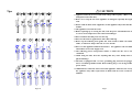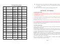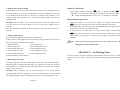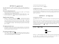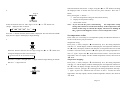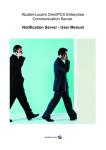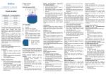
1
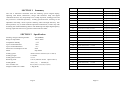
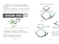
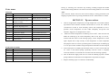
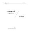
QUICK376D
Self-Feeder Soldering Station
Operation
Manual
Thank you for purchasing a Self-Feeder Lead Free Soldering Station. Please read
this manual before operating the unit. Store this manual in a safe, easily accessible
place for future reference.
Tips
2.5
3
3.5
?1.2
12
45°
12
12
1.5
2
2
2
1.5
7.5
200- 3C
200- 4C
200- J
1.2
R0.2
200- SK
200- K
200- H
3.5
2
3
12
45°
45°
17
R1
R0.2
?0.8
12
200- B
200- I
R0.2
2
12
2
2
12
3.7
10
4
10
12
0.5
0.5
0.5
0.5
0.5
R0.5
?1.6
200- I
200- 0.8C
?1
12
200- 1.2D
?2.4
?3.2
200- 1C
200- 2C
?2
200- 1.6D
200- 2.4D
200- 3.2D
200- 4.2D
200- B
?4.2
30°
?4.7
?3
?3
?4
3.5
25°
3
12
● Appliance shall only be used with rated voltage and frequency. (Refer to the
nameplate back of the unit)
● Don’t use or stop the use if the appliance is damaged, especially the supply
cord.
● Please avoid an abuse of the equipment, use the appliance only in the described
manner.
● The appliance is used in the room.
● Before replacing tip or storing the unit, turn the power off and allow the tip
to cool to room temperature due to the burned danger.
● Don’t touch the metallic parts near the Tip.
● Don’t use the unit for applications other than soldering.
● Don’t rap the soldering iron against the work bench to shake off residual
solder, or otherwise subject the iron to severe shocks.
● Don’t wet the appliance and don’t disconnect the appliance with wet hands
and without to force the supply cord.
● The soldering process will produce smoke, so make sure the area is well
ventilated.
● While using the unit, don’t do anything that may cause bodily harm or
physical damage.
● The unit is equipped with a 3-wires grounding plug and must be plugged
into a 3-terminal grounded socket. Don’t modify plug or use an ungrounded
power socket.
● Children don’t realize the risks of electrical appliance. Therefore use or keep
the appliance only under supervision of adults and out of the reach from
children.
2
2
3
12
12
12
1.5
12
15
45°
45°
45°
45°
Page 24
! CAUTION
Page 1
SECTION 1
Summary
The unit is Automatic self-feeder lead free soldering system. Digital display,
adjusting with button, furthermore, design with automatic sleep and digital
calibration function, easy and prompt to use. Adopt step motor, feeding precise and
the precision is controlled optionally. Feeding speed and time, returning are all
adjustable and steady, reach to perfect soldering effect and high efficiency. One
hand operation, easy to solder. With the optimized combination, it works only with
Soldering Iron without Soldering Station. The Soldering Iron adopts high frequency
heating, rapid heat and recovery speed to realize lead free solder.
SECTION 2
Working voltage of heating element
Range of temperature
Temperature Stability
Tip to Ground Potential
Tip to Ground Resistance
Max Power consumption of unit
Motor
Feeding speed
Feeding Length
Feeding Interval Time
Returning Time
Feeding Mode
Dia. of solder wire
Weight of solder wire usable
Specification
36V/400KHZ
200℃~480℃
±2℃
<2mv
<2Ω
90W
Step Motor
About 2.7mm/s~27mm/s (36°/s~360°/s)
0~150mm
0~2.7s
0~0.9s (About 0~25mm Speed: 360°/s)
Auto (1~9) / Manual (0)
0.5,0.6,0.8,1.0,1.2,1.4,1.6 (mm)
≤1Kg (Roll)
Page 2
15
Feeder Tube Assembly(0.8m)ø1.6mm
16
Guide Tube Assembly ø0.6mm
Using on the top of Tip
17
Guide Tube Assembly ø0.8mm
Using on the top of Tip
18
Guide Tube Assembly ø1.0mm
Using on the top of Tip
19
Guide Tube Assembly ø1.2mm
Using on the top of Tip
20
Guide Tube Assembly ø1.4mm
Using on the top of Tip
21
Guide Tube Assembly ø1.6mm
Using on the top of Tip
22
Guide tube assembly ø0.6mm
Using on the bottom of Tip
23
Guide Tube Assembly ø0.8mm
Using on the bottom of Tip
24
Guide Tube Assembly ø1.0mm
Using on the bottom of Tip
25
Guide Tube Assembly ø1.2mm
Using on the bottom of Tip
26
Guide Tube Assembly ø1.4mm
Using on the bottom of Tip
27
Guide Tube Assembly ø1.6mm
Using on the bottom of Tip
28
Feeder Tube (0.46m) ø0.6mm
29
Feeder Tube (0.46m) ø0.8mm
30
Feeder Tube (0.46m) ø1.0mm
31
Feeder Tube (0.46m) ø1.2mm
32
Feeder Tube (0.46m) ø1.4mm
33
Feeder Tube (0.46m) ø1.6mm
34
Feeder Tube (0.8m)
ø0.6mm
35
Feeder Tube (0.8m)
ø0.8mm
36
Feeder Tube (0.8m)
ø1.0mm
37
Feeder Tube (0.8m)
ø1.2mm
38
Feeder Tube (0.8m)
ø1.4mm
39
Feeder Tube (0.8m)
ø1.6mm
Page 23
and Soldering tip. Put a new Soldering tip on heating element, and tighten nut.
Note: To avoid scald, replacing when it cools down.
2. Replace Fuse
1) Pull Power plug out of Power socket.
2) Take out the fuse holder on the rear side of the unit with screwdriver.
3) Remove the broken fuse and replace it with a new one
4) Fix the fuse holder.
SECTION 18
No.
Replaceable Part
Parts Name
Instruction
1
Pedal Switch
2
Heating Element 90W
3
Soldering Iron 90W
4
Feeder Tube Assembly (0.46m)ø0.6mm
5
Feeder Tube Assembly(0.46m)ø0.8mm
6
Feeder Tube Assembly(0.46m)ø1.0mm
7
Feeder Tube Assembly(0.46m)ø1.2mm
8
Feeder Tube Assembly(0.46m)ø1.4mm
9
Feeder Tube Assembly(0.46m)ø1.6mm
10
Feeder Tube Assembly(0.8m)ø0.6mm
11
Feeder Tube Assembly(0.8m)ø0.8mm
12
Feeder Tube Assembly(0.8m)ø1.0mm
13
Feeder Tube Assembly(0.8m)ø1.2mm
14
Feeder Tube Assembly(0.8m)ø1.4mm
SECTION 3
* Iron soldering adopts high frequency heating, K type sensor, rapid heat and
recovery speed to realize lead free solder. Many kinds of soldering tips with long
service life can be optional and easy to use.
* Digital display, Button adjustment, digital calibration and design with automatic
sleep function.
* Auto and Manual Feeding Mode optional and the times adjustable.
* Feeding Speed and Feeding Length and Feeding Interval Time adjustable, further
more it is designed with Returning function to reduce solder wire consumption.
* Two kinds of Feeder Tube can be chose, and easier and more convenient to using.
Long tube with Manual Touch Switch is suitable for active soldering. Short tube
is suitable for fixed soldering.
* Both of Pedal switch and Manual switch can be use.
* It is used as Lead Feed Soldering Irion.
* ESD safe by design to avoid damaging sensitive element because of static.
SECTION 4
Page 22
Character
Panel Picture
Display Window
Temperature Button
Digital Switch
Power Switch
Page 3
SECTION 5
Combination
* Choose match Soldering Tip in accordance with Soldering Point.
* Choose Solder Wire Ring in accordance with Solder Wire diameter.
* Choose Feeder Tube in accordance with Solder Wire diameter
* Choose Guide Tube Assembly in accordance with Solder Wire diameter.
NOTE: Please fix on Solder Wire diameter when purchasing the unit, in
order to match Feeder Tube Assembly and Solder Wire ring exactly.
SECTION 6
8
Product picture and parts name
3
7
5
6
4
2
1
9
12
If the resistance value is not normal, replace the heating element. After replacing
heating element, please check as follow.
1. Measure the resistance value between pins 4&1 or 2, pins 5&1 or 2, pins 6&1
or 2, pins 6&4 or 5. If it is not ∞, the heating element and sensor are touching.
This will damage the P.W.B.
2. Measure the resistance value ‘a’, ’b’, and ‘c’ to confirm that the lead wire are
not twisted and that the grounding wire is properly connected.
3. To confirm that the clasp ⑨ is clasped with heating element ⑩.
Item No.
Part Name
1
Nut
2
Tip Enclosure
3
Soldering Tip
4
Nip
5
Cord Cover
6
Handle Cover
7
Handle
8
Terminal Board
9
Clasp
10
Heater Combination
11
Vibrator Switch
12
Pin 6 Connector
13
Sensor Spring
14
Heating Element
15
Sensor Element
Instruction
Refer to the last page
Nipple
Metal
10
11
Main Unit
SECTION 17
Replaceable Part
Damageable part can be replaced by customers themselves.
1. Replace Soldering tip
Screw off the metal nut of Soldering tip anti-clockwise and remove tip enclosure
Page 4
Page 21
SECTION 16
Feeder Tube Assembly
Check and replace Heating Element
Disconnect the plug and measure the resistance value between the connecting plug
pins as follows:
If the values of ‘a’ and ‘b’ are outside the below value, replace the heating element
(sensor) and /or cord assembly. If the value of ‘c’ is over the below value, remove
the oxidization film by lightly rubbing with sand-paper or steel wool the points as
shown.
5
a.
Between pins 4&5 (Heating Element)
Under 4Ω (Normal)
b.
Between pins 1 & 2 (Sensor)
Under 10Ω (Normal)
c.
Between pins 3 & Tip
Under 2Ω
Feeder Tube Assembly
17
(0.46m Short Tube)
(0.8m Long Tube)
15
4
6
1
3
13
14
16
2
Feeder Tube (0.46m)
Feeder Tube (0.8m)
1. Turn the nut ① anticlockwise and remove the tip enclosure ② and the tip
③.
2. Turn the nipple ④ anticlockwise and remove it from the iron.
3. Pull Heating Element ⑩ out of Handle ⑦. (Toward the tip of the iron).
4. Do not use metal tools such as pliers to remove tip or Tip enclosure from the
handle.
Measure when the heating element is at room temperature:
1. Resistance value of heating element (white) under 4Ω.
Resistance value of sensor (Red and Green ) under 10Ω.
Page 20
Guide Tube Assembly
(Using for top Feeding )
Guide Tube Assembly
(Using for bottom Feeding)
Page 5
Parts name:
Main unit
Item No.
1, 2
Part Name
Description
Nut
Handle Bracket Assembly
3
Handle clamping element
Handle Bracket Assembly
4
Lead free soldering
handle assembly
5
Handspike
6
Pressure adjusting screw
7
Feeder tube assembly
Optional
8
Solder Wire Axis
Install Solder Wire
9
Solder Wire holder
Install Solder Wire Axis
10
Metal plate
11
Cleaning sponge
12
Pedal Switch
loosing it, returning once and then stop working. Feeding Length and Feeding
Interval and Feeding Mode are all useless when the Feeding Mode is set as manual.
Auto:
Turn on Power Switch. The unit will work according to setting parameters when
stepping on pedal switch or pressing Touch Switch once. All functions are useful
SECTON 15
iron
Tip care and use
1. Choose an appropriate temperature, too high temperature can weaken soldering
tip function and accelerate oxidation and shorten its service life. Under the
circumstance of able to work normally, choose the temperature as low as
possible. Lower temperature can also solder adequately and protect sense
elements. Suggest to set temperature to 350℃。
2. . Make sure set the temperature of soldering iron to 220℃ when use first time.
Make the soldering tip be tinned adequately. Best of all, dip it in tin for 5
Optional Part
minutes and then clean it with cleaning sponge, set the temperature to 300℃
again. Repeat above steps. Finally set the temperature to work temperature.
The purpose of this is to form a protecting film on tinned layer of soldering tip,
so it can prevent the oxidation at high temperature and failure of heat transport.
Feeder Tube Assembly:
Item No.
Part Name
13
Guide Tube
14
Locking Screw
15
Connector
16
Plug
17
Feeder Tube Head
Remark
3. If the tinned part of soldering tip has black oxide, it can be covered with new
tin. Clean it with humid sponge repeatedly until the oxide is completely
removed, and then covered with new tin. Please do this cleaning regularly.
4. Turn off the Power supply when not use. Clean the soldering tip with a cleaning
sponge and then covered with new tin. Repeat above steps when use it again.
5. Replace soldering tip if it is twisted or eroded badly.
Page 6
Page 19
SECTION 13
Temperature Calibration
The Soldering Iron’s temperature should be recalibrated after replacing the iron or
heating element or nozzle every time. The unit adopts digital calibration mode and
the revision value is input by pressing button to make the adjustment simply and
quickly.
Method of recalibrating temperature: Use the thermometer to calibrate , and it is
precise comparatively.
Calibrate by using thermometer
1. Set the unit’s temperature to a certain value.
2. When the temperature stabilizes, measure the tip’s temperature with
thermometer and write down the reading.
3. Press “ * ” button not loose and press the “ ▲ ” and “ ▼ ” button
simultaneously, the unit enters into calibrating temperature mode.
4. At the moment, the 100’s digit of LED display temperature is flashing. Press
the“▲”and“▼” button to select the value and press“*”button to select
the digit. Input the reading of thermometer, and inputting method is the same
as Set temperature normally. Press“*”button after inputting. Here, the
whole calibration operation has been finished.
5. If the temperature still has deflection, you can repeat calibration in accordance
with above steps.
* We recommend to use the 191/192 thermometer for measuring the tip
temperature.
* If the unit is locked by password, it will not be able to calibrate the nozzle
temperature and you must input the right password.
SECTION 14
Operation
Do corresponding operations in accordance with the chosen Feeding Mode.
Manual: (The Mode switch is set as 0)
Turn on power switch and LED window display temperature, the unit is in working
state. Step on Pedal Switch or press the red Touch Switch, and the unit works. After
Page 18
SECTION 7
Installation
Before installation, please check the parts and make sure whether the power supply
voltage accords with the nameplate.
1. Install Handle Bracket assembly to the unit
Screw off the Nut ① of the unit, install bracket assembly on the screw and screw
down the Nut.
2.Install Feeder tube assembly
There are two types of feeder tube assembly optional: Length of 0.46m (Short Tube)
and Length of 0.8m (Long Tube). Installation and operation have a little difference.
Installation of Short Tube:
Screw off the black nipple of handle assembly, install the handle into the connector
and screw on the black nipple again. Unscrew the fixing screw of feeder tube head
on the top cover of unit, insert feeder tube head ⑰ and then tighten the screw.
Installation of Long Tube:
Screw off the black nipple of handle assembly, install the handle into the connector
and screw on the black nipple again. Unscrew the fixing screw of feeder tube head
on the top cover of unit, insert feeder tube head ⑰ and then tighten the screw.
Finally, insert plug ⑯ into socket behind the unit.
3.Install pedal switch
Put the plug of Pedal switch into pin-2 socket behind the unit.
4.Install Solder wire
a. Pull the solder wire axis ⑧ across the framework of solder wire and place it
to the solder wire holder ⑨ back of unit. Make the notch on each side of
solder wire axis lock into solder wire holder.
b. Pull the solder wire head and insert it into wire guide tube behind the top, push
Handspike ⑤ to widen the gap between two running gear wheels, so it can
cross the feeder tube easily.
Page 7
c.
Set the Mode Switch as 0, insert power plug and turn on Power Switch . Make
the feeder tube as straight as possibly, step on Pedal Switch or press down the
red Touch Switch until the solder wire is sent out. Turn off power switch.
5.Install Soldering Iron
Screw off Nut ② on the bracket assembly and remove Handle clamping element ③.
Place soldering iron in the other Handle clamping element and install the previous
one (Make the Handle in the middle of them), and then screw on Nut ②.
Connect plug of soldering iron handle to pin 6 receptacle in front of unit and
tighten it.
6.Adjust the position of Guide tube and Soldering tip
Turn the Connector to change combination location of Guide tube and Soldering tip.
Unscrew Locking Screw ⑭of Guide tube and turn around Guide tube ⑬ can also
change combination location of Guide tube and soldering tip.
7.Adjust direction of soldering iron
When adjust direction, first unscrew the Nut of corresponding direction, and then
adjust. Unscrew the Nut at the bottom end of Bracket assembly and turn around or
rotate Bracket assembly can all adjust direction of Soldering Iron. Finally, tighten
Nut after adjusting.
Unscrew two Nuts ① and ② on top end of Bracket simultaneously and turn
around Handle clamping element can also adjust direction of Soldering Iron.
NOTE:
Please be careful not to break heating element when screw off black nipple to
install connector.
z If step on Pedal Switch or press down the red Touch Switch, the solder wire
can’t be sent out automatically, it needs to adjust feeding pressure―Pressure
adjusting screw ⑥. Refer to parameter setting.
z The Feeder tube can’t be bended overly avoiding the solder wire block.
Page 8
1. If the display windows shows
, press and hold the “▲”or“▼”buttons
simultaneously, then the display shows
X . This indicates the unit comes
into working mode setting state, and pressing “▲” or “▼” button will change
displayed value as shown below:
0
1
2
3
4
5
6
7
0.
1.
2.
3.
4. 5.
6.
7.
2. After selecting the working mode, press “*” down. The working mode is stored
into the internal memory. Please refer to the “Working Mode Table” for the
meaning of the digit displayed.
Note: “X” represents original working mode digit.
Warning:
The heater and Soldering tips will be seriously oxidized or
damaged when working with a high temperature. So please
choose the working mode carefully and try to operate with a
lower temperature if possible.
SECTION 12
Sleeping
If sleeping and working mode are selected, and the unit is not used for 20 minutes,
the power to the heating element will be decreased, and the display shows
.
This state is sleeping mode. When the unit is in sleeping mode, the tip temperature
will decrease to 200℃ (If the set temperature is more than or equal to 200℃) or 50
℃ (If the set temperature is less than 200℃) and remain the temperature until
resuming the unit. To resume soldering, there are several ways as follows:
1. Turn the power switch OFF, then ON.
2. Hit any button.
3. Take up the iron ——Hand Assembly
If the unit is not resumed more than 40 minutes after it comes to sleep, the power
supply will be shut off automatically, and the display window will not show
anything.
Page 17
z
Working Modes Table
WORK
MODE
0
1
2
HANDLE MODE
TEMPERATUE
RANGE
High frequency soldering
iron
High frequency soldering
iron
High frequency special very
large
3
High
frequency
tweezers
stripper iron
4
5
6
7
0.
1.
2.
3.
4.
5.
6.
7.
High frequency soldering
iron
High frequency soldering
iron
High frequency soldering
iron
High frequency soldering
iron
High frequency soldering
iron
High frequency
soldering iron
High frequency tweezers or
using
High
frequency
tweezers
stripper
High frequency soldering
iron
High frequency soldering
iron
High frequency soldering
iron
High frequency soldering
AVAILABLE
AUTO
FOR
SLEEPING&SWI
MAIN
UNIT
TCHING OFF
200℃-420℃
60W Station
Yes
200℃-420℃
90W Station
Yes
200℃-420℃
60
,
90W
Station
Yes
50℃-600℃
90W Station
Yes
50℃-420℃
60W Station
Yes
50℃-420℃
90W Station
Yes
200℃-480℃
60W Station
Yes
200℃-480℃
90W Station
Yes
200℃-420℃
60W Station
No
200℃-420℃
90W Station
No
200℃-420℃
60,90W
Station
No
50℃-600℃
90W Station
No
50℃-420℃
60W Station
No
50℃-420℃
90W Station
No
200℃-480℃
60W Station
No
90W Station
No
200℃-480℃
iron
Page 16
When turn on the power Switch, the soldering Iron begin to heat up
(Temperature lamp is light). In order not to be scalded, please be careful
when installing.
z Make sure the power voltage in accord with working voltage of unit.
SECTION 8
Set Parameter
1. Feeding Speed setting
Feeding speed is set with digital switch. Press “+” button on the digital switch and
the match digit will increase by one step. Similarly, press “-” button, and the match
digit will decrease by one step.
Feeding speed is designed with one digit. 0~9 denotes the feeding speed is about
2.7m/s~27m/s (Angle: 36º/s~360º/s).The resolution is 2.7mm/s, namely, each digit
denotes feeding speed is 2.7m/s. (36º/s)
Example: When the digit is set as 0, the speed is slowest with 2.7mm/s. When it is
set as 1, the speed is 5.4mm/s. When it is set as 9, the speed is fastest with 27mm/s.
Press the Speed Switch to set the suitable digit in accordance with working demand.
The range is about 2.7mm/s to 27mm/s.
2. Feeding Length setting
Feeding Length is designed with angle system, namely, with angle what the motor
turned denotes Feeding Length.
Feeding Length is designed with three digit. 001 to 999 denotes feeding length is
0.15mm to 150mm. The resolution is 0.15mm, namely, each digit denotes 0.15mm
(1.8 degree). The setting method is the same as feeding speed.
Example: When the digit is set as 001, the angle is 1.8 degree and the Speed
Length is 0.15mm. When the digit is set as 002, the angle is 3.6 degree and the
Speed Length is 0.3mm. When the digit is set as 999, the Speed Length is longest
with 150mm, and the angle is 1798.2 degree.
Press the Length Switch to set the suitable digit in accordance with working
demand. The range is about 0.15mm to 150mm.
Page 9
3. Feeding Interval Time setting
Feeding Interval Time means the interval time between every feeding when the
automatic feeding over two times. Feeding Interval Time is designed with one digit.
0 to 9 denotes the interval time is 0 second to 2.7seconds. The resolution is 0.3
second, namely, each digit denotes 0.3 second. The setting method is the same as
Feeding Speed.
Example: When the digit is set as 1, the interval time is 0.3 second. When it is set
as 2, the interval is 0.6 second. When it is set as 9, the time is longest with 2.7
seconds.
Press the Interval Time Switch to choose the digit. The range is 0 second to 2.7
seconds.
4. Feeding Mode setting
Press the Feeding Mode Switch to choose suitable digit.
Feeding Mode is designed with one digit and the setting method is the same as
above. The digital match function as follow:
0: Manual Feeding
1: Auto Feeding once
2: Auto Feeding twice
3: Auto Feeding three times
4: Auto Feeding four times
5: Auto Feeding five times
6: Auto Feeding six times
7: Auto Feeding seven times
8: Auto Feeding eight times
9: Auto Feeding nine times
After each feeding, it has returning.
5. Returning Time setting
Press Returning Switch to set the match digit in accordance with working demand.
Returning Time is designed with one digit. 0 to 9 denotes 0 second to 0.9 second.
The resolution is 0.1 second, namely, each digit denotes 0.1 second. The returning
speed is fixed with 360º/s.
Example: When the digit is set as 1, the returning time is 0.1 second and the
returning length is 2.8mm. The digit is set as 2, the returning time is 0.2 second and
the returning length is 5.6mm. When the digit is set as 9, the returning time is 0.9
Page 10
Input New Password
, press ”*” button, and shows
, It
1. When display window is showing
indicates the unit comes into inputting new password state. Pressing“▲”or
“▼”button will change displayed value. See “set temperature normally”.
Repeat the new password
2. When three digits are selected, press”*” button, the display window shows
again. Now must input the new password. Repeat the same steps.
3. If the password is the same as last time, the changed password is OK. The new
password is stored into the internal memory.
4. If the password is not the same as last time, and the display window shows
, the station will need to rewrite new password. (see the last 8-9 step).
The changing of password is finished until the lately two passwords are
identical.
Note:
The word of password is from 0 to 9, ten words. If not , the
changed password is unsuccessful.
SECTION 11
Set Working Mode
The unit is design with many working modes When the unit leave factory, working
mode is set as seven mode. User don’t change this working mode optionally during
using.
SECTION 10
Set Password
Page 15
The initial password in station’s memory is “000”. The setting temperature is
admitted in this state. If need to restrict the setting temperature, the password must
be changed
Enter into setting the password
1. Turn off the power switch. Press and hold the “ ▲ ” and “ ▼ buttons
simultaneously, then turn on the power switch.
2. Continue holding down the “▲”and“▼”button until the display shows
.
3. When the display shows
,the station is in parameter-input mode.
second and the returning length is 25mm.
The range is about 0 to 25mm. (0 to0.9s)
Page 14
6. Feeding Pressure setting
The solder wire isn’t sent out automatically because of inadequate feeding pressure,
you can adjust Pressure Adjusting Screw on top of unit to increase feeding pressure
clockwise. Solder wire is twisted because of too strong feeding pressure, you can
adjust it anticlockwise.
SECTION 9
Set Temperature
Input Previously Password
Set Temperature Normally
, and the left-most digit (the
4. Press the “*” button, the display shows
100’s digit) in the display will flash. This indicates the station is in password
setting mode and the 100’s digit can be adjusted. Using the “▲”or“▼”button
will change displayed value. Set the password value in the same way described
in “set temperature normally”. After selecting the password of three digit,
press”*” button.
! Caution: Make sure the temperature of the station can be adjusted (password is
△
OK or the password is initial). While setting the temperature normally, the heating
element is off. If the “*” button is pressed less than one second, the present
temperature setting will be shown for two seconds and then the display will return
to showing the tip temperature. “▲”and “▼” are choice button for value . “*” is
choice button for digit.
The input password is error
5. If the display window shows the present setting temperature, two seconds later,
the station is in normal work state. This indicates the password of input is error,
and the temperature setting can’t be done.
Example:
1.
400℃ to 350℃
The password of input is correct
6.
If the display window shows
, this indicates the password of input is
correct. After displaying about 4 seconds, the station comes into normal work
state, and the setting temperature will be admitted.
Press the “*” button and hold it down for at least one second. The left-most digit
(the 100’s digit) in the display will flash. This indicates that the station is in
temperature setting mode and that the 100’s digit can be adjusted.
2.
Page 11
Select the desired value for 100’s digit. Use the “▲” or “▼” button will
change displayed value as follows.
…
2
3
4
…
Press the “*” button when the desired value is displayed. This will cause the middle
digit (the 10’s digit) in the display to begin flashing.
3.
Select the desired value for the 10’s digit. Using the “▲” or “▼” button will
change the displayed value as shown below.
12t3t4t5t6t7t8t9t0
Press the “*” button. The right (the 1’s digit) will then begin flashing to indicate
that the 1’s digit can be set.
4.
Page 12
Select the desired value for the 1’s digit. Using the “▲” or “▼” button will change
the displayed value as shown above for the 10’s place selection.. Press the “*”
button.
Here, pressing the “*” button……
a. Enter the temperature setting into the internal memory.
b. Display the temperature setting.
c. Starts heater control.
Note: If you turn off the power switch during
the temperature setting,
setting value will not be stored in the memory. If the temperature value
outside of this range is selected, the display will return to flashing the
100’s place. If this happens, reenter a correct temperature value
Set temperature on-line
In the work, if it is necessary to set temperature quickly and the heat elements can
not be cut off, the way may be selected.
Temperature rising:
Don’t press “*” knob, and press “▲” knob directly. If so, the setting temperature
will raise 1℃ and the display window will display the set temperature. When loose
the “▲” knob, the display window will delay the set temperature about 2 seconds.
If within 2 seconds of time, press the “▲” knob again, the setting temperature will
raise 1℃ again. If press the “▲” knob and not loose at least 1 second, the setting
temperature will rise rapidly. Till the needed temperature reaches, then loose the
“▲” knob.
Temperature dropping:
Don’t press “*” knob, and press “▼” knob directly. If so, the setting temperature
will drop 1℃ and the display window will display the set temperature. When loose
the “▼” knob, the display window will relay the set temperature about 2 seconds.
If within 2 seconds , press the “▼” knob again, the setting temperature will drop 1
℃ again. If press the “▼”knob and not loose at least 1 second, the setting
temperature will drop rapidly. Till the needed temperature reaches, then loose the
“▼” knob.
Page 13