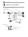
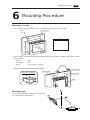
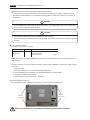
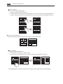
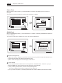
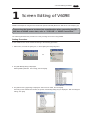
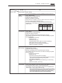
1
Specifications for V609E
HAKKO
TOUCH OPERATION
FLAT PANEL
MONITOUCH
POWER
RUN
V609E
Record of Revision
Printing Date
June, 2001
December, 2003
Reference No.
Revised Contents
1040NE0
First Edition
1040NE1
Second Edition
(A partial revision)
•Available PLCs for multi-drop, multi-link2
and multi-link modified
•Specifications of SRAM & Built-in clock
added
•GD-80E -> V609E Conversion modified
Preface
Thank you for selecting the MONITOUCH V6 series.
For proper set-up, you are requested to read through this booklet to understand more
about the product.
For more information about V6 series, refer to the following manuals.
Contents
Name of Manuals
Ref. No.
Shows wiring for each PLC, setting of
"communication parameter" etc.
V6 Hardware Specifications
2006NEx
The V-SFT operating procedure is
described.
Reference Manual (Operation)
1043NEx
The functions and instructions of V7/V6
series are described.
Reference Manual (Function)
1044NEx
Shows exercises in V-SFT edit.
V-SFT Tutorial
1022NEx
Shows how to connect and set
Temperature Control Network
Temperature Control Network
1033NEx
For further details about the PLC, see the manual attached to each PLC.
Notes:
1. This booklet may not, in whole or in part, be printed or reproduced without the prior written consent of Hakko Electronics Co.,
Ltd.
2. Information in this booklet is subject to change without prior
notice.
Notes on safe usage of MONITOUCH
In this "Specifications for V609E", you will find various notes categorized under the following
three levels with the signal words "Danger," "Warning," and "Caution."
These signal words are to warn the user of possible misuse of the unit. To comprehend the
critical notes on the safe procedure, you must go through this manual before you install
MONITOUCH and operate it correctly.
Danger
DANGER
indicates an imminently hazardous situation which, if not
avoided, will result in death or serious injury.
Warning
WARNING
indicates a potentially hazardous situation which, if not
avoided, could result in death or serious injury.
Caution
CAUTION
indicates a potentially hazardous situation which, if not
avoided, may result in minor or moderate injury and could
cause property damage.
Notes on System Design
WARNING
CAUTION
Never use the input function of MONITOUCH such as the touch switch
for an emergency switch because it could threaten a human life or
break a part of the unit.
Please design the system of the unit in order to respond to a malfunction
of the touch switch.
Prevent the static electricity from being charged on the sheet metal
where MONITOUCH is mounted in order to avoid malfunction caused
by noise.
Never bundle input/output cables with high-voltage and large-current
cables such as power supply cables. Keep input/output cables at least
200mm away from power supply cables in order to avoid malfunction
caused by noise.
As for the use in the facilities related to nuclear energy or in the facilities
of official importance, please consult with our distributer about it.
Notes on Installation
Operate MONITOUCH under the conditions indicated by the manual.
CAUTION
If you don't set the conditions indicated by the manual for the unit, it
could cause fire, malfunction, physical damage or deterioration.
Maintain the following conditions in order to avoid fire or trouble.
Don't let the unit come in contact with corrosive gas, flammable
gas, solvents, grinding fluids or cutting oil.
Never let the unit be exposed to high temperature, high humidity,
and other outside weather conditions.
Don't allow the unit to be exposed to excessive dust, salt, and
metallic particles.
Don't allow the unit to be shaken or hit by other objects.
Equipment must be correctly mounted so that the main terminal will
not inadvertently be touched during an application.
Notes on Cable Connection
DANGER
CAUTION
Turn off the power supply when you set up the system or connect the
cables, otherwise you will get an electric shock or damage the unit.
Connect the cables correctly to the terminals of MONITOUCH in
accordance with the specified voltage and wattage. Over-voltage, overwattage and the incorrect cable connection could cause the unit to be
damaged physically or functionally and also could result in fire.
Ground FG terminal which must be for the unit. The level of grounding
resistance is less than 100Ω.
Prevent any conductive particles from entering into MONITOUCH.
The conductive particles could cause fire, trouble, or malfunction of
the unit.
Notes on Maintenance and Operation
DANGER
Never touch the terminals while the power supply is on, otherwise
you will get an electric shock.
You must put the cover of the terminals on the unit when you turn on
the power and operate it.
The liquid crystal in the LCD panel is a hazardous substance. If the
LCD panel is damaged, never swallow the leaked liquid crystal. If the
liquid crystal spills on your skin or clothing, use soap and wash off
thoroughly.
CAUTION
Hakko Electronics Co., Ltd. is not responsible for an unauthorized
person who may fix, disassemble, or reconstruct any unit.
Avoid displaying the same patterns for hours. It may cause afterimages
due to the property of LCD display. If you use the fixed patterns for
hours, use the auto-OFF function of the backlight.
Contents
1. Hardware Specifications
1. Special Features ................................................................... 1-1
2. Notes on Usage .................................................................... 1-2
3. System Composition ............................................................ 1-4
4. Names of Components ....................................................... 1-7
5. Dimensions and Panel Cut-out ........................................... 1-8
6. Mounting Procedure ............................................................ 1-9
7. Specifications ..................................................................... 1-10
8. Wiring of Power Supply ...................................................... 1-14
9. Serial Connector (CN1) ..................................................... 1-15
10. 1 : 1 Communications ...................................................... 1-19
11. 1 : n (Multi-drop) Communication .................................. 1-20
12. n : 1 (Multi-link 2, multi-link) .............................................. 1-22
13. Modular Jack 1 & 2 .......................................................... 1-26
14. Setting of Dip Switches .................................................... 1-27
15. Barcode Reader Interface .............................................. 1-28
16. Printer Interface (CN2) .................................................... 1-29
17. Specifications of SRAM & Built-in Clock ......................... 1-30
2. System Menu
1. Operation of Main Menu .................................................... 2-1
2. Errors Caused on the V609E .............................................. 2-11
3. Editing &Converting Screen
1. Screen Editing of V609E ....................................................... 3-1
Setting Procedure .............................................................................. 3-1
Restrictions on Creating New Screens with V609E ......................... 3-2
2. GD-80E -> V609E Conversion .............................................. 3-4
CONSIDERATIONS ON HARDWARE ................................................... 3-4
CONSIDERATIONS ON SOFTWARE ..................................................... 3-6
Hardware
Specifications
1. Special Features
2. Notes on Usage
3. System Composition
4. Names of Components
5. Dimensions and Panel Cut-out
6. Mounting Procedure
7. Specifications
8. Wiring of Power Supply
9. Serial Connector (CN1)
10. 1 : 1 Communications
11. 1 : n (Multi-drop) Communication
12. n : 1 (Multi-link 2, multi-link)
13. Modular Jack 1 & 2
14. Setting of Dip Switches
15. Barcode Reader Interface
16. Printer Interface (CN2)
17. Specifications of SRAM & Built-in Clock
1 Special Features
1
1-1
Special Features
1) High-intensity EL Display
Adopts the high-intensity EL device to ensure wide angle of field of view.
Can create easy-to-view screen thanks to orange-yellow display on black background color.
2) High-resolution switch mesh
Uses 40 (W) x 20 (H) touch switches adopting the matrix resistance film.
Allows setting and arranging of switches in a variety of styles.
3) Interface with GD-80E compatibility
Hardware and software designed with replacement of GD-80E (Monitor GD80 series, EL display type)
taken into consideration ensure easy model change.
Inheriting the specifications such as 640 (H) x 400 (V) dot resolution, 8.9-inch screen size and panel cutout
dimensions from GD-80E, V609E is released as user friendly high-level model to ensure smooth replacement of GD-80E.
For the connection to a PLC, the converter to maintain compatibility of wiring is optionally available.
4) Two built-in modular ports
As with V6 series, two built-in ports of modular jack are provided to ensure compatibility to wide range of
functions such as temperature control network and multi-link 2.
* Please note that the maximum baud rate is 57,600 bps.
1-2
1 Notes on Usage
2
Notes on Usage
Environmental Limits
1. Use MONITOUCH at an ambient temperature of
0~50°C, and a relative humidity of 85 %RH.
5. Never install MONITOUCH in a place where
impacts or vibrations may be transmitted.
POWER
RUN
50
40
30
20
10
POWER
0
RUN
2. Install a forced fan or an air conditioner to
maintain the ambient temperature when it is
higher than the above mentioned range.
Fan
6. Avoid any place in which there is the possibility
that water, corrosive gas, flammable gas,
solvents, grinding fluids or cutting oil can come in
contact with the unit. Never install the unit in a
place where dust, salt and metallic particles are
present.
Vent
POWER
RUN
POWER
RUN
YOUZAI
3. Avoid places where moisture may easily condense due to sudden temperature changes.
Locations
1. Secure sufficient space around MONITOUCH for
ventilation.
POWER
RUN
4. Avoid direct sunlight.
POWER
RUN
2. Never attach MONITOUCH to the top of any
apparatus generating high levels of heat (heater,
transformer, large-capacity resistor, etc.).
POWER
RUN
POWER
RUN
1 Notes on Usage
3. Never install MONITOUCH in the same compartment as high-voltage equipment. The unit should
be at least 200 mm away from high-voltage lines
or power cables.
1-3
5. In a dry environment, MONITOUCH may generate
a large amount of static electricity.
Therefore, before touching the unit, touch a
grounded metallic section to discharge the static
electricity.
6. Securely fasten and lock every connector for each
cable. Double-check this before turning the power
on.
POWER
RUN
Lock
!
POWER
Usage
RUN
1. An emergency stop circuit must be composed of
an external relay circuit with a start signal for
MONITOUCH built in. Do not create switches on
MONITOUCH to be used in case of emergency.
7. Application of thinner may discolor MONITOUCH.
Use alcohol or benzine available commercially for
cleaning.
Switch to be used
in emergency
POWER
RUN
POWER
RUN
Emergency
Stop
alcohol
2. In case of using a waterproof sheet (GD-WP80E),
mount it in the unit by using 6 pieces of mounting
screws (normally 4 pieces of them).
BENZINE
8. Never remove any printed circuit board from
MONITOUCH. (This will harm the unit.)
3. MONITOUCH has a glass screen. Never drop or
subject the unit to strong impacts.
POWER
RUN
PO
WE
R
RU
N
9. Never operate the display by using a tool with a
sharp point like a screwdriver.
Touch the display by fingers.
4. Tighten mounting screws with the following
torques.
Position of Screw
Screw Size
Torque (N · m)
Mounting Screw
M3
0.3-0.5 (3-5kgf · cm)
Note :Never fasten these screws too tightly,
otherwise the cover of MONITOUCH may be
deformed.
POWER
RUN
a tool with a
sharp point
like a screwdriver
Notes on Design
1. Use all the display area evenly and avoid using
fixed patterns which may cause afterimages so that
the life span of the display can be expanded.
1-4
3
1 System Composition
System Composition
System Composition/Model Indication/Peripheral Equipment
System Composition
The following illustration shows possible system configurations using V609E.
Panel Editor
for V series
During operation
(Link communication)
Transferring
screen data
Creating screens
RUN
RS-232C/RS-422
disc
V6-CP
STOP
Æ Æ Æ
Æ Æ Æ
Æ Æ Æ
Æ Æ Æ
Æ Æ Æ Æ Æ Æ
Æ Æ Æ Æ Æ Æ
Æ Æ Æ Æ Æ Æ
Æ Æ Æ Æ Æ Æ
Æ Æ Æ
Æ Æ Æ
Æ Æ Æ
Æ Æ Æ
POWER
RUN
RESET
V-SFT
V609E
Personal Computer (PC)
Transferring
screen data
V6-CP
During operation
(Universal serial
communication)
Transferring
screen data
or
Memory manager
/Data logging
RS-232C/RS-422
CREC-CP
Card Recorder
CREC
Universal-purpose
computer
Cable
V6-BCD
Printer Cable
V6-PT
Barcode Reader
Cable
V6-TMP
Printer
PV
SV
SET
R/S
Temperature Controller
Model Indication
V609E30M
Blank : 100-240VAC type
D
: 24VDC type (Comply with CE/UL/cUL)
Matrix type (Touch switch)
3 : SRAM + Built-in clock function
High-intensity EL (Display Device)
Link Unit
1 System Composition
1-5
Peripheral Equipment
The following options are available for using V609E more effectively.
V-SFT (Panel Editor for Windows98/NT4.0/Me/2000/XP)
Application software for editing display data for V series.
V6-CP (Data Transfer Cable) 3m
Connects V6 to a personal computer, or a personal computer to CREC.
V6-PT (Printer Cable) 2.5m
Connects V6 to a printer.
* When using CBM292/293 printer, our printer cable “V6-PTCBM” is available.
CREC (Card Recorder)
Reads display data created by personal computer, or works as an external
memory storage system for the memory manager and data logging functions.
REC-MCARD (Memory Card)
H
C
U
O
IT
N
O
M
Complies with JEIDA Ver.4.0
Used as a recording medium for display data back-up and for the memory
manager or data logging function.
SRAM 256K, 512K, 1M, 2M, 4Mbyte
FLASH ROM 256K, 512K, 1M
F
56
C2
RE
M-CARD SFT (Memory Card Editor)
Application software for editing data stored in a memory card.
(For Windows98/NT 4.0/Me/2000/XP)
V-I/O (Serial Extension I/O)
Used as an external I/O unit for PLC. It has 16 inputs and 16 outputs.
DC24V
IN1
FG
IN0
IN2
IN3
IN4
IN5
IN6
IN7
IN8
MJ1
IN9
IN10
IN11
IN12
IN13
IN14
IN15
OUT1
COM+
OUT0
OUT2
OUT3
OUT4
OUT5
OUT6
OUT7
COM1
OUT8
OUT9
OUT10
OUT11
OUT12
OUT13
OUT14
OUT15
COM2
1-6
1 System Composition
TC485 (Terminal Converter)
CN
1
Used for connection between a V6 and a PLC at the RS-422/485 terminal
block.
SW
1
TB
1
V-MDD (ACPU/QnACPU/FXCPU Dual Port Interface)
G
P
P
V -M
123
GD
DD
Add-on connector with two ports, specifically designed for the connector on
the MITSUBISHI's ACPU/QnACPU/FXCPU programmer. This can improve
operability of the ACPU/QnACPU/FXCPU programmer that is directly
connected.
TC609 (Terminal converter for V609E)
The communication board that allows the use of existing communication
cable used with GD-80E.
V6-BCD (Cable for Barcode Reader) 3m
Connects V6 to a barcode reader.
V6-MLT (Cable for Multi-Link 2 master station) 3m
A cable which is used for connecting the V6 master station and the V6 slave
station in the Multi-Link 2 connection.
V6-TMP (Cable for Temperature Controller) 3m
Connects V6 to a temperature controller.
GD-GS80E (Protection Sheet)
Protects the operation panel surface. Five sheets are included in one
package.
GD-WP80E (Waterproof Sheet)
Protects the operation panel surface from water.
1 Names of Components
4
1-7
Names of Components
Front Side
POWER
RUN
Rear Side
RUN / STOP
L
100240VAC
N
NC
TYPE
: V609 x x x
LOT No.
:
INPUT
: 100 - 240 VAC
CURRENT : 0.6 - 0.4A
Hakko Electronics Co., Ltd.
MADE IN JAPAN
CN1
MJ2
MJ1
CN2
1.
2.
3.
4.
5.
6.
7.
8.
Mounting holes for fixtures
Display
Power lamp
RUN lamp
AC / DC input terminal of power supply
RUN/STOP switch
CN1: for PLC (RS-232C, RS-422)
MJ1, 2: for data transfer and for temperature controller and for barcode reader and for CREC
(option)
9. Dip switches
10. CN2: for printer
1-8
1 Dimensions and Panel Cut-out
5
Dimensions and Panel Cut-out
Dimensions of V609E
Unit : mm
Rear View
Bottom View
RUN / STOP
276
L
95
85
100240VAC
N
TYPE
: V609 x x x
LOT No.
:
INPUT
: 100 - 240 VAC
CURRENT : 0.6 - 0.4A
Hakko Electronics Co., Ltd.
MADE IN JAPAN
CN1
NC
MJ2
10
CN2
Front View
Side View
191
203
288
POWER
RUN
Panel Cut-out of V609E
+1
-0
+1
-0
277
192
Unit : mm
Panel Cut-out
MJ1
1 Mounting Procedure
6
1-9
Mounting Procedure
Mounting Procedure
1. Cut out the mounting panel (Max. thick: 5 mm) to match the dimensions shown below.
Mounting Panel
Cut-out
+1
277- 0
192 +1-0
-0
192 +1
-0
277 +1
POWER
Panel Cut-out
RUN
2. Insert 4 pieces of the fixtures attached to V609E into the mounting holes on V609E. Tighten them with the
locking screws.
Screws
: 4 pcs
Screw Size
: M3
Torque
: 0.3~0.5 N·m (3~5 kgf·cm)
Fixtures
* Never use 6 pieces of the fixtures to mount V609E.
Mounting panel
Dimensions of Fixtures
Mounting hole
Mounting hole
(Unit : mm)
26
25
V609E
10
Mounting Angle
D
p
is
y
la
The unit (V609E) shall be installed within the angle of
0 to 135 degrees as shown below.
Display
1-10
7
1 Specifications
Specifications
General Specifications
Type
AC Power Supply
DC Power Supply
100-240V AC
24V DC
85-265V AC (47-440Hz)
24V DC 10
Permissible Momentary Power Failure
within 20ms
within 10ms
Demand
40VA or less
20W or less
10A, 2ms
24A,10ms
AC external terminals to FG
: 1500V AC per min.
DC external terminals to FG
: 500V AC per min.
Item
Rated Voltage
Power Supply
Permissible Range of Voltage
Rushed Electric Current
With-stand Voltage
500V DC, 10M
Mechanical
Working
Conditions
Physical Environment
Insulation Resistance
0
Ambient Temperature
Ambient Humidity
No conductive dust
No cutting oil or no organic solvent to cling to the unit
No corrosive gas
Corrosive Gas
Vibration Resistance
~+65
85% RH or less (without dew condensation)
Dust
Solvent Resistance
~+50
-10
Storage Ambient Temperature
or more
Vibration frequency: 10~150Hz, Acceleration: 9.8m/s2 (1.0G)
3 directions of X, Y and Z: one hour
Shock Resistance
Pulse shape: Sine half wave,
2
Electrical
Working
Conditions
Peak acceleration: 147m/s (15G), 3 directions of X, Y and Z: 2 times
Noise Resistance
Contact: 6kV, Air: 8kV
Static Electricity Discharge Resistance
Grounding
Structure
Mounting Conditions
1500Vp-p (noise width: 1 s)
Grounding resistance: less than 100
Protection structure: front panel complies with IP64
(when using waterproof screen filter GD-WP80E)
rear panel complies with IP20
Form: in a body
Mounting procedure: inserted in a mounting panel
Cooling naturally
Cooling System
Weight
Approx. 2.1kg
Dimensions W x H x D (mm)
288 x 203 x 95
+1
+1
277 -0 x 192 -0
Panel Cut-out (mm)
Case Color
GREY
BLACK
Material
ABS
PC/PS
1-11
1 Specifications
Display Specifications
Type
Item
V609E
Display Device
High-intensity EL
Resolution W x H (dots)
640 x 400
Dot Pitch W x H (mm)
0.3 x 0.3
Effective Display Area W x H (mm)
192 x 120 (8.9 inches)
Color
Black/orange-yellow + blinking
POWER Lamp (red)
The lamp is lit when the power is supplied.
RUN Lamp (green)
The lamp is lit when V6 communicates with PLC normally.
Display Function Specifications
Item
Specifications
Display Language *
Japanese
Eng./W. Europe
Chinese
Chinese (simplified)
Korean
Characters
ANK code
Latin 1
ASCII code
ASCII code
ASCII code
1/4-size, 1-byte
2-byte (16-dot) JIS 1st and 2nd
2-byte (32-dot)
Size of Characters
Chinese
Chinese (simplified) Hangul (without Kanji)
JIS 1st
1/4-size : 8 X 8 dots
1-byte : 8 X 16 dots
2-byte : 16 X 16 dots or 32 X 32 dots
Enlarge : W, 1-8 H, 1-8
Number of Characters
1/4-size
80 columns X 40 lines
1-byte
80 columns X 20 lines
2-byte
40 columns X 20 lines
Property of Characters
Display property : normal, reverse, blinking, bold, shadow
Color : black/orange-yellow + blinking
Kind of Drawing
Lines : line, continuous lines, box, parallelogram, polygon
Circles : circle, arc, sector, ellipse, elliptical arc, elliptical sector
Others : tile patterns
Property of Drawing
Type of lines : 6 types (fine, thick, dot, chain, broken, two-dot chain)
Tile patterns : 16 types (incl. user-definable 8 types)
Display property : normal, reverse, blinking
Display color : black/orange-yellow + blinking
Color specification : foreground, background, boundaries (line)
* Concerning Gothic font, use of this font is not recommended since the V609E screen memory capacity
(see the next page) could not be sufficient.
1-12
1 Specifications
Function Performance Specifications
Specifications
Item
Screens
Max. 1024
Screen Memory
FP-ROM (flash ROM), Appox. 760kbytes (different from the language)
Switches
192 per screen
Actions of Switch
Set, reset, momentary, alternate, to light
(possible to press a function switch and a display switch at the same time)
Lamps
Reverse, blinking, exchange of graphics
192 per screen
*
Data Setting
Graphs
Pie, bar, panel meter and closed area graph can be displayed without limit.
Total capacity per screen: within 48kB
Statics and trend graphs: Max. 256 per layer
Numerical Data Display* No limits, total capacity per screen: within 48 kB
Character Display
Message Display
*
*
No limits, total capacity per screen: within 48 kB
Resolution : Max. 80 characters
No limits, total capacity per screen: within 48 kB
Messages
6144 lines
Sampling
Sampling display of buffer data
(constant sample, bit synchronize, bit sample, relay sample, alarm function)
Multi-Overlaps
Max. 1024
Data Blocks
Max. 1024
Graphic Libraries
Max. 2560
Patterns
Max. 1024
Macro Blocks
Max. 1024
Page Blocks
Max. 1024
Direct Blocks
Max. 1024
Screen Blocks
Max. 1024
Temperature Control Network Table Max. 32
Calendar
provided
Hard-Copy
provided
Buzzer
provided, 3 types (intermittent short, long, continuous beeps)
Back-light Auto OFF Function ON at all time, specified freely
Self-diagnostic Function
Self-test function of switches
Check function of communication parameter setting
Check function of communication
* Number of the setting memory per screen: 256
1 Specifications
1-13
Touch Panel Specifications
Item
Specifications
Switch Resolution
40 (W) X 20 (H)
Form
Matrix resistance film form
Life of Touch Panel
Use of one million times or more
Surface treatment
Hard coating, anti-glare treatment 5%
Interface Specifications
Item
Specifications
Serial Interface
RS-232C, RS-422/485
for connecting PLC
Asynchronous type
(D-sub 25 pins, female)
Data length: 7, 8 bits
Parity: even, odd, none
Stop bit: 1, 2 bits
Baud rate: 4800, 9600, 19200, 38400, 57600bps
Serial Interface 1 and 2 for
RS-232C, RS-422/485 (2-wire connection)
transferring data/barcode
*When CREC, an optional equipment, is connected:
/CREC
1 slot
(modular jack, 8 pins)
SRAM: Max. 4 MB
FROM: Max. 16 MB
Comply with JEIDA Ver. 4.0 (The limit exists.)
Printer Interface
Complies with centronics, half pitch 36 pins (for PC98x1)
NEC
: PR201
EPSON : compatibles with ESC/P24-84 or later
HP
: PCL Level 3
CBM292/293 printer (The screen copy cannot be printed out.)
MR-400 printer (The hard copy, data sheet and sampling data
cannot be printed out.)
Drawing Environment
Item
Specifications
Drawing Method
Exclusive drawing software
Drawing Tool
Name of exclusive drawing software
Personal computer
OS
: V-SFT Ver. 1.2.18.0 or later
: Pentium ll 450MHz or more is recommended
: Microsoft Windows 98/NT version 4.0/Me/2000/XP
Capacity of hard disk required
(For minimum installation
Display
: free area of approx. 460MB or more
: Approx. 105MB)
: Resolution of 800 X 600 or more is recommended
1-14
1 Wiring of Power Supply
8
Wiring of Power Supply
Electrical Wiring
Connects the cable for power supply to the terminal on the
rear side of V609E.
Type: 100-240VAC
RUN / STOP
Type: 24VDC
L
Power Supply
100240VAC
TYPE
: V609 x x x
LOT No.
:
INPUT
: 100 - 240 VAC
CURRENT : 0.6 - 0.4A
Hakko Electronics Co., Ltd.
MADE IN JAPAN
L
100240VAC
+
N
CN1
NC
MJ2
MJ1
24 VDC
-
N
CN2
NC
NC
Earth
V609E
Earth
Screw Size
M3.5
Clamp Terminal (Unit : mm)
Torque (N m)
0.5 (5kgf cm)
8.0MAX
8.0MAX
The power source used must be within the allowable voltage fluctuation.
Use a power source with low noise between the cables or ground and the cable.
Use as thick a power cable as possible to minimize any drop in voltage.
Keep cables of 100V AC and 24V DC sufficiently away from high-voltage, large-current cables.
Notes on Usage of 100-240V AC Specifications
Generally, an isolating transformer improves noise resistance. However, if the display unit is far away from
the secondary port of the transformer and noise gets mixed in, an isolating transformer becomes unnecessary.
If any power voltage fluctuation caused by noise is expected, it is recommended that a voltage stabilizer
(effective in noise resistance) be used.
Power Supply
Insulation transformer
or
Stabilized transformer
Grounding
to V609E
2
1.25mm twisted
This equipment must be earthed.
An independent earth pole shall be used for MONITOUCH. (The level
of grounding resistance should be less than 100 Ω.)
Use a cable which has a nominal cross section of more than 2mm2 for
grounding.
Grounding point shall be near the MONITOUCH to shorten the distance
of grounding wires.
V6
Other Equipment
1 Serial Connector (CN1)
9
1-15
Serial Connector (CN1)
CN1 is used for communicating between a PLC and a V609E (RS-232C, RS-422/485).
Interface Specifications
Item
Specifications
Serial Interface
RS-232C, RS-422/485
for connecting PLC
Asynchronous type
(D-sub 25 pins, female)
Data length: 7, 8 bits
Parity: even, odd, none
Stop bit: 1, 2 bits
Baud rate: 4800, 9600, 19200, 38400, 57600bps
Serial Connector (CN1)
The pin arrangement of serial connector is as follows:
CN1 (Dsub 25pin)
Female
25
13
RUN / STOP
Pin No.
Signal
1
FG
Frame ground
2
SD
RS-232C send data
3
RD
RS-232C receive data
4
RS
RS-232C RS request to send
5
CS
RS-232C CS clear to send
Not used
6
7
SG
8
L
100240VAC
N
TYPE
: V609 x x x
LOT No.
:
INPUT
: 100 - 240 VAC
CURRENT : 0.6 - 0.4A
Hakko Electronics Co., Ltd.
MADE IN JAPAN
NC
Contents
Signal ground
Not used
9
+5V
Use prohibited
10
0V
Use prohibited
CN1
MJ2
MJ1
14
1
11
Not used
CN2
V609E
12
+SD
13
-SD
RS-422 send data (-)
14
+RS
RS-422 RS send data (+)
15
Not used
16
17
RS-422 send data (+)
Not used
-RS
RS-422 RS send data (-)
18
-CS
RS-422 CS receive data (-)
19
+CS
RS-422 CS receive data (+)
20
Not used
21
Not used
22
Not used
23
Not used
24
+RD
RS-422 receive data (+)
25
-RD
RS-422 receive data (-)
1-16
1 Serial Connector (CN1)
Wiring for Communication
Never place the communication cable with electric circuits.
Never bundle these cables together with other wires in ducts or electric boxes using cord locks. Although it
is tempting to bundle all the cables neatly together, this does not necessarily lead to a noise-resistant
configuration.
It is recommended that the communication cable be independently wired.
Wiring duct
Communication cable
Communication cable
Power cable and control cable
Power cable and control cable
Cord lock
In Case of RS-232C Communication
In case of RS-232C, SD and SG, and RD and SG form a pair.
Connect the shielded cable to pin No. 1 or the connector case cover.
V609E (CN1)
Signal
Pin No.
Shielded cable
To the RS-232C port
of the PLC link unit
FG
1
Receive data
SD
2
SG
RD
3
SG
RS
4
Send data
CS
5
SG
7
In Case of RS-422 Communication
In case of RS-422, +SD and -SD, and +RD and -RD form a pair.
Use SG if possible.
Connect the shielded cable to pin No. 1 or the connector case cover.
Use TC485 or TC609 which is the optional equipment made by Hakko Electronics Co., Ltd. in case of
using terminal blocks in RS-422/485 connection.
Specify terminal resistance by the dip switches on V6. (Refer to the next page.)
V609E (CN1)
Signal
Pin No.
Shielded cable
To the RS-422 port
of the PLC link unit
FG
1
+RD
24
Send data (-)
-RD
25
Send data (+)
+SD
12
Receive data (-)
-SD
13
Receive data (+)
SG
7
SG
1-17
1 Serial Connector (CN1)
Terminal Blocks of RS-422/485
Connect TC485 (Terminal Converter) which is the optional equipment made by Hakko Electronics Co., Ltd.
to V6 via the serial connector on V609E (CN1) in case of using terminal blocks in RS-422/485 connection.
The RS-422 signal wiring of TC485 is connected to the serial connector (CN1).
Specify 4-wire connection or 2-wire connection by the dip switch on TC485 (SW1).
(set to top: 4-wire connection)
RUN / STOP
TYPE
: V609 x x x
LOT No.
:
INPUT
: 100 - 240 VAC
CURRENT : 0.6 - 0.4A
Hakko Electronics Co., Ltd.
MADE IN JAPAN
L
100240VAC
N
CN1
NC
MJ2
MJ1
CN
1
CN2
SW
1
TB
1
V609E
TC485
CN1
SW1
(Set to top:
4-wire connection)
Signal
Pin No.
FG
1
TC485 (Terminal Converter)
TB1
RD+
SG
7
+SD
12
RDSD+
SDSG
-SD
13
+RD
24
-RD
25
FG
Terminal Converter (TC609) for V609E
To use the existing wiring, used for GD-80E, when replacing GD-80E with V609E, connect the TC609
(Terminal Converter for V609E), optional equipment made by Hakko Electronics Co., Ltd. to the serial
connector (CN1).
Signal wiring of D-sub 15 pins and RS-422 terminal block of TC609 is connected to the serial connector
(CN1).
D-sub 15 pin port of TC609 is equivalent to the connector on GD-80E where CPU port direct connection
cable (MB-CPU) for Mitsubishi A/QnA/Fx series is connected. The RS-422 terminal block of TC609 is
equivalent to the RS-422 terminal block of standard specification GD-80E.
* For details, refer to "User's Manual of TC609 (Terminal Converter for V609E)."
RUN / STOP
L
100240VAC
N
TYPE
: V609 x x x
LOT No.
:
INPUT
: 100 - 240 VAC
CURRENT : 0.6 - 0.4A
Hakko Electronics Co., Ltd.
MADE IN JAPAN
NC
CN1
MJ2
MJ1
CN2
Top View of TC609
V609E
CN1
CN3 TB1
+RD
-RD
+SD
-SD
SG
FG
TC609 (Terminal Converter for V609E)
1-18
1 Serial Connector (CN1)
Connection Style
Three kinds of V609E to PLC connection styles are available as shown below.
PLC
1:1
In this style, a single V609E is connected to a single PLC.
For details, refer to "10 1 : 1 Communications."
V609E
RUN
STOP
. . .
. . .
. . .
. . .
. . .
. . .
. . .
. . .
. . .
. . .
. . .
. . .
. . .
. . .
. . .
. . .
POWER
RUN
To be connected through RS-232C or RS-422 (RS-485) interface.
1 : n (multi-drop)
In this style, multiple PLCs are connected to a single V609E. (n = 1 to 31)
For details, refer to "11 1 : n Communications."
V609E
POWER
RUN
To be connected through RS-422/485 interface
Max. 500 m
RUN
STOP
. . .
. . .
. . .
. . .
. . .
. . .
. . .
. . .
. . .
. . .
. . .
. . .
. . .
. . .
. . .
. . .
RUN
STOP
PLC1
. . .
. . .
. . .
. . .
. . .
. . .
. . .
. . .
. . .
. . .
. . .
. . .
. . .
. . .
. . .
. . .
RUN
STOP
PLC2
. . .
. . .
. . .
. . .
. . .
. . .
. . .
. . .
. . .
. . .
. . .
. . .
. . .
. . .
. . .
. . .
RUN
STOP
PLC3
. . .
. . .
. . .
. . .
. . .
. . .
. . .
. . .
. . .
. . .
. . .
. . .
. . .
. . .
. . .
. . .
PLCn
n : 1 (multi-link 2, multi-link)
In this style, multiple V6s are connected to a single PLC.
(Multi-link 2: n = 1 to 4, Multi-link: n = 1 to 31)
For details, refer to "12 n : 1 (multi-link 2, multi-link)."
"V6" 1
"V6" 2
"V6" 3
"V6" n
POWER
POWER
POWER
POWER
RUN
RUN
RUN
RUN
RUN
STOP
. . .
. . .
. . .
. . .
. . .
. . .
. . .
. . .
. . .
. . .
. . .
. . .
. . .
. . .
. . .
. . .
To be connected through RS-485 interface
Max. 500 m
* Connection as show below is not recommended.
PLC
POWER
POWER
POWER
RUN
RUN
RUN
RUN
STOP
. . .
. . .
. . .
. . .
. . .
. . .
. . .
. . .
. . .
. . .
. . .
. . .
. . .
. . .
. . .
. . .
1 1 : 1 Communications
10
1-19
1 : 1 Communications
In this style, a single V609E is connected to a single PLC.
PLC
V609E
RUN
STOP
. . .
. . .
. . .
. . .
. . .
. . .
. . .
. . .
. . .
. . .
. . .
. . .
. . .
. . .
. . .
. . .
POWER
RUN
To be connected through RS-232C or RS-422 (RS-485) interface.
Connection to a PLC
About the wiring, communication parameter, etc. in connection between V609E and a PLC, refer to ‘Chapter 2
Connection to Link Units’ of “V6 Hardware Specifications.”
1-20
1 1 : n (Multi-drop) Communications
11
1 : n (Multi-drop) Communication
One V6 and multiple PLCs are connected. (n = 1 to 31)
V609E
POWER
RUN
To be connected through RS-422/485 interface
Max. 500 m
RUN
STOP
. . .
. . .
. . .
. . .
. . .
. . .
. . .
. . .
. . .
. . .
. . .
. . .
. . .
. . .
. . .
. . .
PLC1
RUN
STOP
. . .
. . .
. . .
. . .
. . .
. . .
. . .
. . .
. . .
. . .
. . .
. . .
. . .
. . .
. . .
. . .
PLC2
RUN
STOP
. . .
. . .
. . .
. . .
. . .
. . .
. . .
. . .
. . .
. . .
. . .
. . .
. . .
. . .
. . .
. . .
PLC3
RUN
STOP
. . .
. . .
. . .
. . .
. . .
. . .
. . .
. . .
. . .
. . .
. . .
. . .
. . .
. . .
. . .
. . .
PLCn
Available PLC for multi-drop communication
Manufacturer
MITSUBISHI ELECTRIC
SHARP
Hitachi
Matsushita Electric Works
Yokogawa Electric
Yaskawa Electric
Toyoda Machine Works
Fuji Electric
KOYO ELECTRONICS
Allen-Bradley
GE Fanuc
Models
A series link, QnA series link, QnH(Q) series link, Alink+Net10,
FX series link(A prt)
SYSMAC C, SYSMAC CV, SYSMAC CS1/CJ1,
SYSMAC CS1/CJ1 DNA
JW series, JW100/70H COM port, JW20 COM port
HIDIC-H
MEWNET
FA500, FA-M3, FA-M3R
MEMOBUS, CP9200SH/MP900
TOYOPUC
MICREX-F series, FLEX-PC series, FLEX-PC COM(T)
SU/SG, SR-T
PLC-5, SLC500, Micro Logix 1000
90 series
TOSHIBA
Siemens
SHINKO ELECTRIC
SAMSUNG
KEYENCE
T series
S7-200 PPI, S7-300/400MPI*
SELMART
SPC series, N_plus, SECNET
KZ series link, KZ/KV series CPU
LG
FATEK AUTOMATION
IDEC
MASTER-K500/1000, MASTER-KxxxS CNET, GLOFA CNET
FACON FB series
MICRO3, MICRO Smart
MODICON
TAIAN
Modbus RTU
TP02
Universal Serial
OMRON
* Up to 4 PLCs can be connected.
1 1 : n (Multi-drop) Communications
Multi-drop Communication (RS-422)
Refer to the PLC manual of each manufacturer for connection.
<E.g.>
The following example describes how one V609E is connected to three PLCs made by MITSUBISHI.
See MITSUBISHI’s manual for further details.
V609E (CN1)
Link unit
Link unit
Link unit
Signal Pin No.
Signal
Signal
Signal
FG
FG
FG
FG
1
+SD
12
RDA
RDA
RDA
-SD
13
RDB
RDB
RDB
+RD
24
SDA
SDA
SDA
-RD
25
SDB
SDB
SDB
SG
7
SG
SG
SG
SD/RD terminal resistance
(ON)
* Use twist shielded cable.
1-21
1-22
1 n : 1 (Multi-link 2, multi-link)
12
n : 1 (Multi-link 2, multi-link)
Multiple V6s are connected to a single PLC.
In this style, there are two kinds of communications.
n : 1 Link Communication (Multi-link2)
Up to 4 units can be connected to one PLC.
* Between a PLC and the V6 master station is the same as those for 1:1 communication.
PLC
Communication between the stations : RS-485 (2-wire system) Maximum length: 500 m
(b)
CN1
MJ2
V6 master
(Station 1)
terminal
(a)
(c)
(d)
CN1
V6 slave
(Station 2)
(e)
CN1
V6 slave
(Station 3)
CN1
V6 slave
(Station 4)
Available PLCs for multi-link2.
As of December 2003, the PLCs supported are as follows. All the PLCs which are usable for 1:1 communication will be supported.
Manufacturer
MITSUBISHI ELECTRIC
Models
A series link, A series CPU, QnA series link, QnA series CPU,
QnH(Q) series link, QnH(A) series CPU, QnH(Q) series CPU,
OMRON
Q00J/00/01 CPU, FX series CPU, FX2N series CPU,
FX1S series CPU, FX series link(A prt)
SYSMAC C, SYSMAC CV, SYSMAC CS1/CJ1
SHARP
Hitachi
Matsushita Electric Works
Yokogawa Electric
Yaskawa Electric
JW series, JW100/70H COM port, JW20 COM port
HIDIC-H, HIDIC-S10/2alpha, HIDIC-S10/ABS
MEWNET
FA500, FA-M3, FA-M3R
MEMOBUS, CP9200SH/MP900
Toyoda Machine Works
Fuji Electric
TOYOPUC
MICREX-F series, MICREX-F series V4, FLEX-PC series,
FLEX-PC CPU, FLEX-PC COM(T), FLEX-PC series(T),
KOYO ELECTRONICS
Allen-Bradley
GE Fanuc
TOSHIBA
TOSHIBA MACHINE
Siemens
FLEX-PC CPU(T)
SU/SG, SR-T, SR-T(K prt), SU/SG(K-Sequence)
PLC-5, SLC500, Micro Logix 1000, Control Logix
90 series, 90 series(SNP-X)
T series, EX series
FANUC
FATEK AUTOMATION
TC200
S5, S5 PG port, S5 V4, S7, S7-300MPI(HMI ADP),
S7-300MPI(PC ADP), S7-300MPI(Helmholz SSW7 ADP),
TI500/505, TI500/505 V4
SPC series, N_plus, SECNET
KZ series link, KZ-A500 CPU, KZ/KV series CPU, KZ24/300 CPU,
KV10/24 CPU, KV-700 CPU
MASTER-K10/60/200, MASTER-K500/1000, MASTER-KxxxS,
MASTER-KxxxS CNET, GLOFA CNET, GLOFA GM series CPU
Power Mate
FACON FB series
IDEC
MODICON
Yamatake
MICRO3, MICRO Smart
Modbus RTU
MX series, DMC50
TAIAN
TP02
SAMSUNG
KEYENCE
LG
1-23
1 n : 1 (Multi-link 2, multi-link)
For the I/F driver, the Multi-Link 2 is supported by the version of 1.100 or later and as for a V6 master
station, make sure the hardware version of the unit is as follows. As for V609E/V606/V606i, any version
can be used.
· Analog type: V612T --> D, V612C --> C, V610S --> D, V610T --> D, V610C --> C, V608C --> F
· Matrix type : All version
* When V609E (or V606/V606i) is used as a master, V6 models that can be connected as a slave are only V609E,
V606 and V606i.
* The Multi-Link 2 cannot be used in Temperature control network.
Up to 4 units can be connected to one PLC.
Use the terminal converter (TC485), the optional equipment made by Hakko Electronics Co., Ltd.
See Multi-link2 manual for further details.
* Wire the shielded FG only at the one of both sides so that they are not connected.
• Set the dip switch (SW1) of TC485 as 2-wire connection when the TC485 terminal converter is used.
(b)
V6 master
MJ1/2
+
-
SG
Terminal resistor
(ON)
(c)
(d)
(e)
Terminal block
prepared by user
V6 slave
CN1+TC485
Signal
Signal
Signal
FG
FG
FG
+
+RD
+RD
+RD
-
-RD
-RD
-RD
+SD
+SD
+SD
-SD
-SD
-SD
SG
SG
SG
Terminal resistor
(OFF)
Terminal resistor
(OFF)
Terminal resistor
(ON)
SG
V6 slave
CN1+TC485
V6 slave
CN1+TC485
Signal
• Short-circuit between +RD and +SD, and -RD and -SD when the TC485 terminal converter is not used.
1-24
1 n : 1 (Multi-link 2, multi-link)
n : 1 Link Communication (Multi-link)
Multiple V6 and a PLC are connected. (n=1 to 31)
"V6" 1
"V6" 2
"V6" 3
"V6" n
POWER
POWER
POWER
POWER
RUN
RUN
RUN
RUN
RUN
STOP
. . .
. . .
. . .
. . .
. . .
. . .
. . .
. . .
. . .
. . .
. . .
. . .
. . .
. . .
. . .
. . .
To be connected through RS-485 interface
Max. 500 m
* Connection as show below is not recommended.
PLC
POWER
POWER
POWER
RUN
RUN
RUN
RUN
STOP
Available PLCs for multi-link
Manufacturer
MITSUBISHI ELECTRIC
SHARP
Hitachi
Matsushita Electric Works
Yokogawa Electric
Toyoda Machine Works
Fuji Electric
TOSHIBA
TOSHIBA MACHINE
Siemens
SHINKO ELECTRIC
SAMSUNG
LG
Models
A series link, Alink+Net10, FX series link(A prt),
QnA series CPU (with V-MDD)
JW series, JW100/70H COM port, JW20 COM port
HIDIC-H
MEWNET
FA500, FA-M3, FA-M3R
TOYOPUC
MICREX-F series, FLEX-PC COM(T)
T series
TC200
S7-200 PPI, S7-300/400MPI*
SELMART
SPC series, N_plus, SECNET
MASTER-K500/1000
* Up to 3 units can be connected to one PLC.
. . .
. . .
. . .
. . .
. . .
. . .
. . .
. . .
. . .
. . .
. . .
. . .
. . .
. . .
. . .
. . .
1-25
1 n : 1 (Multi-link 2, multi-link)
When multiple V6 are connected to a link unit of PLC, use the terminal converter (TC485), the optional
equipment made by Hakko Electronics Co., Ltd. for RS-485 connection.
• Set the dip switch (SW1) of TC485 as 2-wire connection when the TC485 terminal converter is used.
V6+TC485
V6+TC485
V6+TC485
Link unit
Signal
Signal
Signal
Signal
FG
FG
FG
FG
+SD
+SD
+SD
+RxD
-SD
-SD
-SD
-RxD
+RD
+RD
+RD
+TxD
-RD
-RD
-RD
-TxD
SG
SG
SG
SG
RD/SD terminal resistance
(OFF)
RD/SD terminal resistance
(OFF)
RD terminal resistance
(ON)
* Use twist shielded cable.
• Short-circuit between +RD and +SD, and -RD and -SD when the TC485 terminal converter is not used.
When multiple V6 are connected directly to MITSUBISHI’s QCPU port, the optional equipment, V-MDD is
required. Make sure to use V-MDD GD port. (It is recommended to use “TC485 Terminal Converter”
which is an optional equipment made by Hakko Electronics Co., Ltd..)
• Set the dip switch (SW1) of TC485 as 2-wire connection when the TC485 terminal converter is used.
V6+TC485
V6+TC485
V6+TC485
V-MDD
GD port
Signal
Signal
Signal
Pin No. Signal
FG
FG
FG
1
+SD
+SD
+SD
2
-SD
-SD
-SD
3
+TxD
+RD
+RD
+RD
4
+DSR
-RD
-RD
-RD
5
+DTR
SG
SG
SG
7
SG
15
-RxD
RD terminal resistance
(ON)
RD/SD terminal resistance
(OFF)
* Use twist shielded cable.
RD/SD terminal resistance
(OFF)
+RxD
16
-TxD
17
-DSR
18
-DTR
20
21
• Short-circuit between +RD and +SD, and -RD and -SD when the TC485 terminal converter is not used.
1-26
1 Modular Jack 1 & 2
13
Modular Jack 1 & 2
Modular Jack 1 & 2 (MJ1/2)
The right diagram is the pin arrangement and the
signal name of modular jack 1 & 2.
MJ1/2
12345678
Pin No.
1
2
3
4
5
6
7
8
Signal
+SD/RD
-SD/RD
+5V
+5V
0V
0V
RD
SD
Output power supply
Max. 150mA
Setting of Modular Jack 1 & 2 (MJ1/MJ2)
Specify the use of MJ1/MJ2 by the software (V-SFT).
Select [Modular] of [System Setting], and then the [Modular Jack] dialog is displayed. The setting items of
[Modular Jack 1] and [Modular Jack 2] in this dialog are as follows.
Modular Jack 1
Modular Jack 2
[Editor port]
[Not used]
[Memory Card]
[Memory Card]
[Barcode]
[Barcode]
[V-I/O]
[V-I/O]
[Multi-Link] *
[Multi-Link] *
[Temp./ PLC2Way]
[Temp./ PLC2Way]
[V-Link]
[V-Link]
[Modbus Slave]
[Modbus Slave]
[Printer(Serial Port)]
[Printer(Serial Port)]
It is impossible to select both [Multi-Link] and [Temp./ PLC2Way] in each setting of modular jack.
* It is possible to select this item when [Multi-Link 2] is selected for [Connection] and [Local Port] is set to [1] in
the [Comm. Parameter] dialog.
Editor Transferring
Use modular jack 1 (MJ1) in case of editor transferring.
When [Editor port] is selected for [Modular Jack 1] in the [Modular Jack] dialog, it is also possible to
transfer the data while running, because the auto change of the local mode and the run mode is valid.
When [Editor port] is selected, on-line editing and the simulation mode are also available.
When the item other than [Editor port] is selected for [Modular Jack 1] in the dialog, be sure to transfer the
data by the software in the local mode. On-line editing and the simulation mode are not available.
When the data is transferred by software, use the cable for data transferring which is the optional equipment made by Hakko Electronics Co., Ltd. (V6-CP: 3m) to connect V609E to a personal computer.
1 Setting of Dip Switches
14
1-27
Setting of Dip Switches
Setting of Dip Switches
ON
1
2
3
4
5
6
7
8
Terminal resistance of MJ2 (modular jack 2)
Not used
RD terminal resistance of pin No. 24 and 25 in CN1
Terminal resistance of MJ1 (modular jack 1)
Setting of Terminal Resistance
• Set DIPSW 7 ON in case of connecting V6 to PLC by RS-422/485.
• Set DIPSW 6 (DIPSW 8) ON in case of connecting with Modular Jack 1/2 by the connection as shown
below.
Multi-link 2 communication (master)
Temp./ PLC2Way communication by connection of RS-485
Card Recorder : CREC (option) is used
Serial Extension I/O : V-I/O (option) is used
Terminal V609E connected with V-Link by connection of RS-485
Keep DIPSW 1, 2, 3, 4, 5 and 8 (not used) OFF.
1-28
1 Barcode Reader Interface
15
Barcode Reader Interface
It is possible to receive the signal from a barcode reader by connecting a barcode reader to V609E via the
modular jack (MJ1/MJ2) of V609E.
12345678
To connect a barcode reader to V609E via MJ1/MJ2, use the cable which is the optional equipment made
by Hakko Electronics Co., Ltd. (V6-BCD).
Length
: 3m
Brown : +5V
Red : 0V
Orange : RXD
Yellow : TXD
Notes on Connection
• In case of using the barcode reader which uses the CTS and RTS control, the barcode reader may
not work normally without jumping RTS and CTS.
• The output power supply (+5V) is max. 150mA. (Refer to page 1-26.)
12345678
When the barcode reader connected to GD-80E is used, connect it to V609E by the following cable.
Barcode Reader
Signal
RTS
TXD
RXD
CTS
SG
+5V
D-sub 9pin ( )
Pin No. Signal
1
CTS
2
RXD
3
TXD
4
RTS
5
6
7
SG
8
9
+5V
*
Orange : RXD
Yellow : TXD
* Jump pins, 1(CTS) and 4(RTS).
Red : 0V
Brown : +5V
1 Printer Interface (CN2)
16
1-29
Printer Interface (CN2)
When a printer is connected to V609E via the connector (CN2), it is possible to hard-copy the screen
display of V609E, the data sheet, or the sampling data.
To connect a printer to V6, use the parallel interface cable of 36 pins which is optional equipment made by
Hakko Electronics Co., Ltd. (V6-PT: 2.5m)
When using CBM292/293 printer, our printer cable “V6-PTCBM” is available.
* The printer cable for GD-80 or V4 cannot be used.
RUN / STOP
L
100240VAC
N
TYPE
: V609 x x x
LOT No.
:
INPUT
: 100 - 240 VAC
CURRENT : 0.6 - 0.4A
Hakko Electronics Co., Ltd.
MADE IN JAPAN
NC
CN1
MJ2
MJ1
CN2
V609E
to Printer
Half pitch 36 pins
Centronics
Compatible Printer Control Code System and Printer Models
NEC
PC-PR201 series
EPSON
Compatibles with ESC/P24-84 or later
HP(HEWLETT PACKARD)
PCL Level 3
CBM292/293
MR400
Line thermal panel printer made by CBM Corporation
(The screen copy cannot be printed out.)
Barcode printer [MR400 series] made by Sato Corporation
(The hard copy, the data sheet, and the sampling data cannot be
printed out.)
Note of Usage of SRAM Memory Card (via CREC);
In case of connecting a printer to V609E with a “REC-MCARD(Memory Card:SRAM)” at all times, be sure to
turn off a printer at the same time when turning off V609E. If a printer is not turned off when V609E is turned
off, the voltage will circulate from the power supply line of a printer to make the power consumption of SRAM
cassette’s backup battery increase, and finally, the backup battery will consume drastically within a few
months.
1-30
1 Specifications of SRAM & Built-in Clock
17
Specifications of SRAM &
Built-in Clock
Memory Specifications
Specifications
Item
Memory Type
SRAM
Memory Capacity
8kbytes
Backup Specifications
Specifications
Item
Battery Specification
Lithium primary battery of coin type
Battery model : CR2430 (SANYO)
Backup Period
5 years (at the temperature of 25
Replacement
Available (battery is attached to a socket)
Detection of Voltage for Battery Lowering
Calendar Precision
)
Available (internal memories allocated)
Remainder on a month ±90 seconds (at the temperature of 25°C)
Notes on Usage of SRAM & Clock Function
Check if the battery is set when using SRAM or clock function. The contents of SRAM may not be
maintained if the electric power for SRAM is cut off.
(The factory-shipped configuration is with the battery set.)
Refer to the next item, “How to Check the Battery,” about the way to check the battery condition.
Use the following versions of each program file:
V-SFT
version 1.3.1.0 or later
System program
version 1.510 or later
Font data
version 1.210/1.140/1.000 or later
How to Check the Battery
[Caution seal]
The battery is set in V609E30M when shipped from the
factory.
The standard backup period (5 years) is written down in
the section of the ‘Battery replacement‘ of the caution
seal on the rear side of V609E30M.
The date after 5 years is
written down when shipped
from the factory.
L
100240VAC
N
TYPE
: V609 x x x
LOT No.
:
INPUT
: 100 - 240 VAC
CURRENT : 0.6 - 0.4A
Hakko Electronics Co., Ltd.
MADE IN JAPAN
CN1
NC
MJ2
MJ1
CN2
*The life of battery for V609E30M is about 5 years at
25˚C. Even if 5 years don’t pass, when the battery
voltage has dropped, bit 4 of $s167 is set (ON) to give an alarm about battery replacement. Replace the battery
immediately then.
MSB
$s167
LSB
15
14
13
12
11
10
09
08
07
06
05
0
0
0
0
0
0
0
0
0
0
0
Memory cassette information reservation
(setting: 0)
04
03
02
0
0
01
00
0: SRAM & clock not attached
(= V609E10Mx used)
3: SRAM & clock attached
(= V609E30M used)
Memory cassette information reservation (setting:0)
1: Battery error (replacement necessary)
1 Specifications of SRAM & Built-in Clock
1-31
How to Set SRAM and Clock
How to Set SRAM
Make sure if the battery is set before starting the following procedures.
1. Specify the necessary setting of the [SRAM/Clock Setting] in the [System Setting] when editing the
screen data file.
2. Transfer the screen data file to V609E.
3. Pressing the [SRAM/Clock] switch of the [Main Menu] screen to the [SRAM/Clock Adjustment] screen,
and execute the format of SRAM.
After that, the area of SRAM in V609E30M is to be available.
How to Set Clock
Make sure if the battery is set before starting the following procedures.
1. Check [Use Built-in Clock] of the [SRAM/Clock Setting] in the [System Setting] when editing the screen
data file.
2. Transfer the screen data file to V609E.
3. Pressing the [SRAM/Clock] switch of the [Main Menu] screen to the [SRAM/Clock Adjustment] screen,
and set the calendar.
After that, the clock function in V609E30M is to be available.
Replacement of Battery
Safety Precaution for Handling a Battery
The lithium battery encloses inflammable materials such as lithium and organic solvent. Therefore,
wrong handling of the lithium battery may cause personal injury or fire. Thoroughly pay attention to the
following cautions when handling the lithium battery to prevent unintended accidents.
CAUTION
· Be sure and discharge the build-up of static electricity before installing, inspecting and maintaining the
product.
· When replacing a battery, be sure and use the same battery as mentioned above. Use of another
battery may prevent a risk of fire or explosion.
· The battery used in this device may present a fire or chemical burn hazard if mistreated.
· Do not disassemble, heat or incinerate the battery.
· When scrapping the spent battery, insulate the terminals with applying tape to them and follow local
ordinances or regulations for its disposal.
· Keep away the battery from children. (Please immediately consult with a doctor if children have
swallowed the battery.)
· Do not short-circuit.
· Do not charge.
· Do not solder directly on to batteries.
· Do not use the battery with the direction of +/- reversed.
· When the battery is leaking or giving out a foul smell, keep away the battery from fire right away,
because there is the danger that the leaking electrolysis liquid is caught fire.
1-32
1 Specifications of SRAM & Built-in Clock
Safety Precaution for Handling V609E in Battery Replacement
Understand the procedure described in this manual before replacing the battery. Hakko Electronics
assumes no responsibility for any accidents caused by failure to follow the replacement procedure in
this manual
DANGER
· Turn off V609E before attempting to replace the battery. Set V609E aside until it cools. Failure to do
so may result in an electric shock or burns.
CAUTION
· Wear gloves or fingerstalls when replacing the battery.
· Take necessary measures to protect V609E from static electricity.
· Do not touch cables and boards that are not associated with battery replacement. Doing so may result
in failure.
How to Replace Battery
The battery for replacement is prepared.
Name
Model
V609E Battery for
Replacement
V6EM/RB
Composition
· Lithium primary battery of coin type
(SANYO CR2430)
· A seal for caution
1 pce
1 copy
V609E can maintain the data in SRAM when the battery is replaced within 3 minutes after removing the
original battery.
If it takes 3 minutes or more to replace the battery, save the data in SRAM by using V-SFT (cable: V6-CP)
as follows.
1. Start the V-SFT.
2. Click the [Transfer] icon. The [Transfer] dialog is displayed.
3. Choose [Display] for [Transfer Device], and [SRAM Data] for [Transfer Data].
4. Click [PC<-] under [Transfer Mode].
5. The read data is to be stored in the “*.RAM” file.
Replace the battery as follows:
1. Turn off V609E, and turn it upside down as follows. Remove the 4 external screws.
Remove
the screws.
Remove
the screws.
Place it on a cloth, etc. to protect the display panel from scratches.
1-33
1 Specifications of SRAM & Built-in Clock
2. Remove the rear external case softly according to the following direction to show the internal PC board.
Front external
case
Remove the rear
external case softly.
Rear external
case
Battery
Do not remove the cables connecting the front case to the rear case.
Doing so may result in failure.
3. Disconnect the battery from the connector.
Remove the battery at the side of
in the battery connector by pressing it in the direction of the
side.
side
Battery
side
4. Replace it with a new one.
Set the battery with the
the
side upward. When setting the battery, put it at the side of
side by pressing it in the direction of the
side.
5. Close the rear case of V609E.
6. Attach the 4 external screws.
7. Remove the caution seal from V609E.
Write down the date after 5 years in the section of the
replacement date of the caution seal, and put up the seal on
the rear of V609E.
8. Turn on V609E.
Transfer the RAM file in the case of saving it before the replacement.
, and then, put it in
1-34
Please use this page freely.
System Menu
1. Operation of Main Menu
2. Errors Caused on the V609E
2-1
2 Operation of Main Menu
1
Operation of Main Menu
When the power of V6 is turned on for the first time, the screen on the below left is displayed. After transferring the screen data to V6, the following "Main Menu" is displayed.
When power is turned on for the first time:
"Main Menu" after transferring data
V609E30M
Main Menu
1998- 5 - 5 9: 0: 20
SYS PROG.VER.1.430
I/O Test
MemoryCard
FONT VER.1.210/1.100/1.000
JAPANESE 32
Comm.Para.
I/F DRV VER.1.200
MELSEC AnA/N/U
PLC Type : MITSUBISHIAnA/N/U series
Comment :
POWER
POWER
RUN
RUN
SRAM/Clock
Editor:MJ1
If the screen data has been already transferred to V6, press the [RUN/STOP] switch on the rear side.
The [Main Menu] is displayed.
RUN/STOP switch
on the rear side
"Main Menu" after transferring the screen data
Main Menu
SW 1
V609E30M
SYS PROG.VER.1.430
FONT VER.1.210/1.100/1.000
JAPANESE 32
xxx
240 VAC
0.4A
Co., Ltd.
JAPAN
1998- 5 - 5 9: 0: 20
I/O Test
MemoryCard
Comm.Para.
I/F DRV VER.1.200
MELSEC AnA/N/U
CN1
MJ2
PLC Type : MITSUBISHIAnA/N/U series
Comment :
MJ1
POWER
RUN
Editor:MJ1
CN2
SRAM/Clock
2-2
2 Operation of Main Menu
Main Menu
The "Main Menu" is the system menu for transferring the data between a personal computer and V6.
When the screen data is transferred from a personal computer to V6, the "Main Menu" or “Comm. Parameter”
(see page 2-10) must be displayed.
(If [Editor port] is selected for [Modular Jack 1] in the [Modular] of the editing software, it is not necessary to
display the "Main Menu.")
Model name of V609E
System Program version
V609E30M
Main Menu
1998- 5 - 5 9: 0: 20
SYS PROG.VER.1.430
Font data version
2.
MemoryCard
FONT VER.1.210/1.100/1.000
JAPANESE 32
PLC I/F driver
version and name
1.
I/O Test
Comm.Para.
3.
I/F DRV VER.1.200
MELSEC AnA/N/U
PLC Type : MITSUBISHIAnA/N/U series
Comment :
4.
SRAM/Clock
POWER
RUN
Editor:MJ1
PLC type and comment
specified by the panel editor
I/O Test
When the switch '1.' on the "Main Menu" is pressed, the following "I/O Test" is displayed.
This is the test menu to check only V609E hardware.
D
I/O Test
Main Menu
Printer Chcek
Serial Test
B
Switch Check
POWER
RUN
A
C
2 Operation of Main Menu
2-3
A. Self-loop Test
Pressing the switch ‘A’ on the “I/O Test” brings to the [Serial Test] screen.
This is the test menu to check the signals necessary for V6 to communicate with PLC or a personal computer
by using only V6.
Serial Test
I/O Test
Self-Loop Test
Please refer to the manual, "Hardware Specifications".
CTS
RTS
NG
OK
Communication Port
Self-Loop
Test
CN1
RS232C
MJ1
RS485
MJ2
POWER
RUN
Signal Test of RS-232C in CN1
Select [CN1] and [RS-232C] in [Communication Port] by pressing each switch.
CTS
RTS
NG
OK
Self-Loop
Test
Communication Port
CN1
RS232C
MJ1
RS485
MJ2
Loop-back Test
Check the [SD] and [RD] signals.
1. Jump pins, 2 and 3 of CN1.
2. The test is OK, if the [OK] lamp turns on when the [Self-Loop Test] switch is pressed.
CTS
NG
RTS
OK
Self-Loop
Test
Communication Port
CN1
RS232C
MJ1
RS485
MJ2
CTS
RTS
NG
OK
Self-Loop
Test
Communication Port
CN1
RS232C
MJ1
RS485
MJ2
* If the [NG] lamp turns on when the same switch as above is pressed, ask the advice of your distributor.
2-4
2 Operation of Main Menu
Test of CTS/RTS
Check the [CTS] and [RTS] signals.
1. Jump pins, 4(RTS) and 5(CTS) of CN1.
2. The test is OK if the [CTS] lamp and the [RTS] lamp turn on at the same time that the [RTS] switch is
pressed. Similarly, the test is OK if the [CTS] turns off at the same time that the [RTS] is turned off.
CTS
RTS
CTS
RTS
NG
OK
NG
OK
Self-Loop
Test
Self-Loop
Test
CTS
RTS
CTS
RTS
NG
OK
NG
OK
Self-Loop
Test
Self-Loop
Test
Signal Test of RS-485 in CN1
Select [CN1] and [RS-485] in [Communication Port] by pressing each switch.
CTS
RTS
NG
OK
Self-Loop
Test
Communication Port
CN1
RS232C
MJ1
RS485
MJ2
Loop-back Test
Check the [SD] and [RD] signals.
1. Jump each pin, 12 and 24, 13 and 25 of CN1.
2. The test is OK, if the [OK] lamp turns on when the [Self-Loop Test] switch is pressed.
CTS
RTS
Communication Port
CN1
NG
OK
Self-Loop
Test
MJ1
MJ2
CTS
RTS
NG
OK
RS232C
RS485
Self-Loop
Test
Communication Port
CN1
RS232C
MJ1
RS485
MJ2
* If the [NG] lamp turns on when the same switch as above is pressed, ask the advice of your distributor.
2 Operation of Main Menu
2-5
Test of CTS/RTS
Check the [CTS] and [RTS] signals.
1. Jump each pin, 14(+RTS) and 19(+CTS), 17(-RTS) and 18(-CTS) of CN1.
2. The test is OK if the [CTS] lamp and the [RTS] lamp turn on at the same time that the [RTS] switch is
pressed. Similarly, the test is OK if the [CTS] turns off at the same time that the [RTS] is turned off.
CTS
RTS
CTS
RTS
NG
OK
NG
OK
Self-Loop
Test
Self-Loop
Test
CTS
RTS
CTS
RTS
NG
OK
NG
OK
Self-Loop
Test
Self-Loop
Test
Signal Test of RS-232C in MJ1 and MJ2
Select [MJ1] (or [MJ2]) and [RS-232C] in [Communication Port] by pressing each switch.
CTS
RTS
NG
OK
Communication Port
Self-Loop
Test
CN1
RS232C
MJ1
RS485
MJ2
Loop-back Test
Check the [SD] and [RD] signals.
Execute the test by connecting the data transfer cable (V6-CP) to CN1.
1. Set the adaptor, ADP25-9, which is attached to V6-CP, to V6-CP. And connect the modular jack side
of V6-CP to MJ1 (or MJ2), ADP25-9 side of V6-CP to CN1.
V6-CP
CN1
MJ1/2
2. The test is OK, if the [OK] lamp turns on when the [Self-Loop Test] switch is pressed.
CTS
RTS
Communication Port
CN1
NG
OK
Self-Loop
Test
MJ1
CTS
RTS
NG
OK
RS232C
RS485
MJ2
Self-Loop
Test
Communication Port
CN1
RS232C
MJ1
RS485
MJ2
* If the [NG] lamp turns on when the same switch as above is pressed, ask the advice of your distributor.
Signal Test of RS-485 in MJ1 and MJ2
When you execute the signal test of RS-485 in MJ1 and MJ2, ask the advice of your distributor.
2-6
2 Operation of Main Menu
B. Printer Check
Check the signal of printer.
The test is OK if the test printout is executed satisfactorily when connecting V609E to a printer and pressing
this [Printer Check] switch (B).
!"#$%&@
!"#$%&@
!"#$%&@
!"#$%&@
!"#$%&@
!"#$%&@
!"#$%&@
0123456789
0123456789
0123456789
0123456789
0123456789
0123456789
0123456789
ABCDEFGHIJKLMNO
ABCDEFGHIJKLMNO
ABCDEFGHIJKLMNO
ABCDEFGHIJKLMNO
ABCDEFGHIJKLMNO
ABCDEFGHIJKLMNO
ABCDEFGHIJKLMNO
C. Switch Check
Check the reaction of the touch switches on the V609E panel.
When the [Switch Check] switch (C) is pressed, the following screen is displayed.
Confirm that the color of the pressed area changes into orange-yellow.
The orange-yellow color means that the switch reacts to the touch normally.
Pressing the corner right below [*] leads to the previous [I/O Test] screen.
Main Menu
Printer Check
Serial Test
Switch Check
POWER
RUN
If the pressed area is
reversed, these switches
reacts to the touch normally.
D. Main Menu
Pressing this [Main Menu] switch (D) leads to the previous [Main Menu].
Main Menu
Main Menu
V609E30M
SYS PROG.VER.1.430
FONT VER.1.210/1.100/1.000
JAPANESE 32
Printer Check
1998- 5 - 5 9: 0: 20
I/O Test
MemoryCard
Comm.Para.
I/F DRV VER.1.200
MELSEC AnA/N/U
Serial Test
PLC Type : MITSUBISHIAnA/N/U series
Comment :
Switch Check
POWER
RUN
Editor:MJ1
SRAM/Clock
2 Operation of Main Menu
2-7
Memory-Card
When the [Memory-Card] switch (2.) on the "Main Menu" is pressed, the following "Memory-Card" is displayed.
This screen is to transfer the screen data between V609E and a memory-card.
Memory-Card
Main Menu
Port Selection
Transfer
Modular Jack
MJ1
Display <-- Card
Data Selection
Screen Data
Display --> Card
Display <-> Card
I/F Driver
Start
Font Data
Cancel
Sys Program
POWER
RUN
Procedure of Data Transferring
1) Port Selection
Select the [Modular Jack MJ1] switch (or [Modular Jack MJ2]) in case of using a modular jack.
When each switch is pressed, the “Memory-Card Information” window is displayed.
Pressing the “Close” switch leads to the original screen after checking the memory card information.
Memory-Card
Memory-Card
Transfer
Modular Jack
MJ1
Display <-- Card
Modular Jack
MJ1
Sys Program
:
Display --> Card
Font Data
Data :Selection
Display <-> Card
Screen
Data
I/F Driver
:
VERSION : - . - - -
Data Selection
Screen Data
Main Menu
Close
Transfer
Port Selection
Memory-Card
Information
Port Selection
Display <-- Card
Display --> Card
VERSION : - . - - - / - . - - - / - . - - -
I/F Driver
Start
Font Data
Cancel
I/F
Driver: - . - - VERSION
Screen PLC Type :
Screen Font
Comment
Data :
Display <-> Card
Start
Cancel
Sys Program
Sys Program
POWER
POWER
RUN
RUN
* In case of selecting [Card Recorder] from [Modular Jack 2] on V-SFT and transferring data, it is possible to
select the [Modular Jack 2] switch in the [Port Selection] menu of the [Memory-Card] screen on V6.
2-8
2 Operation of Main Menu
2) Data Selection, Transfer
Pressing each switch leads to selection of the target for data transferring. (Possible to select multiple
items.)
Data Selection
Memory-Card
Transfer
Modular Jack
MJ1
Display <-- Card
Screen Data
Memory-Card
Main Menu
Port Selection
Data Selection
Transfer
Display --> Card
Main Menu
Port Selection
Transfer
Modular Jack
MJ1
Display <-- Card
Display --> Card
Data Selection
Display <-> Card
Screen Data
Display <-> Card
I/F Driver
Start
I/F Driver
Start
Font Data
Cancel
Font Data
Cancel
Sys Program
Sys Program
POWER
POWER
RUN
RUN
3) Start
When the [Start] switch is pressed, the data transferring starts. During data transfer, the character, the
lamp of ‘Start’ switch is turned ON.
After transferring data, the following message is displayed. Press the [OK] switch.
Start transferring
Memory-Card
Transfer
Modular Jack
MJ1
Display <-- Card
Screen Data
Memory-Card
Main Menu
Port Selection
Data Selection
During transferring
Display --> Card
Transfer
Modular Jack
MJ1
Display <-- Card
Data Selection
Display <-> Card
Main Menu
Port Selection
Screen Data
Display --> Card
Display <-> Card
I/F Driver
Start
I/F Driver
Start
Font Data
Cancel
Font Data
Cancel
Sys Program
Sys Program
POWER
POWER
RUN
RUN
Finish transferring
Memory-Card
WorkPort
normally
finished
Selection
Modular Jack
MJ1
O K
Data Selection
Screen Data
RUN
Display <-- Card
Display --> Card
Display <-> Card
I/F Driver
Start
Font Data
Cancel
Sys Program
POWER
Main Menu
Transfer
2 Operation of Main Menu
Message Display in Data Transferring
If an error occurs during transferring data, the message display
window shown on the right is displayed. The kinds and the contents
of the messages are as shown below.
Message
2-9
Work normally finished
O K
Contents
Work normally finished.
The specified operation has been concluded normally.
CREC not connecting
CREC is not connecting when selecting a modular jack.
CREC Communication Error
A communication error occurred between V6 and
CREC when selecting a modular jack.
Memory-Card not setting
A memory card is not inserted.
Memory-Card Capacity over
Cannot write the data into a memory card because
the data size in V6 is larger than the capacity of
a memory card.
Write Protect : ON
Cannot write data into a memory card because
the write protect switch in a memory card is ON.
Writing Error occurred.
The error occurred while writing data into a memory
card.
Selected data does not exist.
The data in the reading target does not exist.
V6 type is different.
The specified type of the data in V6 is different from the
type of the memory card data.
Selected data can not be read.
The data in a memory card cannot be read.
Reading Error occurred.
The error occurred during writing data into a flash
ROM of V6.
Data discrepant
There is some discrepancy in data, when comparing data
between a memory card and V6.
Screen data on V6 will be broken.
This message appears to inform the user that the data in
V6 will be broken by transferring the font data (the size
which is larger than the present data) from a memory
card to V6. (The [OK] switch continues the transferring.
The [Cancel] switch stops transferring.)
Undefined Error occurred.
The error occurred due to some cause other than
the above mentioned.
2-10
2 Operation of Main Menu
Comm. Para.
When the [Comm. Para.] switch (3.) on the "Main Menu" is pressed, the following "Comm. Param." is
displayed.
This screen is to show the setting of communication parameter of V609E.
Main Menu
V609E30M
SYS PROG.VER.1.430
1998- 5 - 5 9: 0: 20
Comm. Param.
Main Menu
I/O Test
Screen Data Size : 786432
MemoryCard
FONT VER.1.210/1.100/1.000
JAPANESE 32
Error:Retry
Time-Out:0.50sec
Retry:3
Comm.Para.
I/F DRV VER.1.200
MELSEC AnA/N/U
PLC Type : MITSUBISHIAnA/N/U series
Comment :
Connection:1:1
Signal Level:RS232C
PLC Stat. No.:00
SRAM/Clock
POWER
Baud Rate:19200
Data Length:7
Stop Bit:1
Parity:Even
Send Delay: 0msec
POWER
RUN
RUN
Editor:MJ1
Editor:MJ1
SRAM/Clock
When the [SRAM/Clock] switch (4.) on the "Main Menu" is pressed, the following "SRAM/Clock Adjustment"
screen is displayed.
This screen is to adjust the V609E built-in clock, and format the SRAM area.
Main Menu
V609E30M
SYS PROG.VER.1.430
FONT VER.1.210/1.100/1.000
JAPANESE 32
1998- 5 - 5 9: 0: 20
SRAM/Clock Adjustment
I/O Test
Date:
Time:
Comm.Para.
I/F DRV VER.1.200
MELSEC AnA/N/U
PLC Type : MITSUBISHIAnA/N/U series
Comment :
POWER
<-
Main Menu
1998- 5- 5
9: 0: 20
->
+
Set
-
Format of SRAM
SRAM/Clock
* Formats SRAM cassette in the present screen data type.
POWER
RUN
1998- 5 - 5 9: 0: 20
Date and Time Adjustment
MemoryCard
Format
Execute
RUN
Editor:MJ1
Data and Time Adjustment
1) Move the cursor by using [->] or [<-] switch, and then use [+] or [-] switch to adjust both date and time.
2) Press the [Set] switch after adjusting both date and time.
3) Both of them are displayed in the time display located above.
Format of SRAM
Format of SRAM makes the data which is currently stored in the SRAM erased. Whenever you try to
format the SRAM area, take note about this and perform the format carefully.
1) First, press the [Format] switch, and then do the [Execute] switch.
The format of SRAM is performed in the present screen data type.
2) The [** Format Completed **] message appears after the format of SRAM is performed successfully.
2 Errors Caused on the V609E
2
2-11
Errors Caused on the V609E
Communication Error
The followings are the errors which are often caused on the V6 series.
About any other errors except these errors, refer to ‘Appendix 3 Error’ in “Reference Manual (Function).”
* When you go to [Comm. Parameter],
bring up the [Detail] tab window and
set [Continuous] for [Comm. Err.
Handling], a screen like the one
shown below is displayed.
Communication Error
Time-Out
Screen No. :
Received code No. :
RETRY
Communication Error
Time-Out
POWER
This portion of the
message changes.
RUN
Message
Time-Out
*
Contents
Although a request is
sent for transmission to
the PLC, an answer is
Line 1
Line 2
Line 3
Monitor 1
Monitor 2
Monitor 3
Error 1
Error 2
Error 3
Solution
Remarks
1) Check the communication parameter.
A
2) Check the cable and wiring.
3) Data may be disrupted because of
B
noise. Fix noise.
Error code received
not returned within the
required amount of time.
An error code was sent Solve the problem by examining the
CPU error code.
Check I/F driver
to the link unit by the
CPU of the PLC.
When sending a communication request to a
personal computer
(simulator), there is no
reply from a personal
computer.
I/F driver for PLC again.
(applicable to I/F
driver for Simulator)
If a simulator is not used, transfer the
* If the above error messages are displayed on the V609E without establishing
communication between V609E and PLC, test the solution of remark "A."
If the error occurs suddenly in communication, test the solution of remark "B."
2-12
2 Errors Caused on the V609E
System Error
When a system error is detected, the following error screen is displayed.
SYSTEM ERROR : 32
TEA : XXXXXXXX
R0 : XXXXXXXX
R4 : XXXXXXXX
R8 : XXXXXXXX
R12 : XXXXXXXX
EXPEVT : XXXXXXXX
R1 : XXXXXXXX
R5 : XXXXXXXX
R9 : XXXXXXXX
R13 : XXXXXXXX
SSR : XXXXXXXX
R2 : XXXXXXXX
R6 : XXXXXXXX
R10 : XXXXXXXX
R14 : XXXXXXXX
SPC : XXXXXXXX
R3 : XXXXXXXX
R7 : XXXXXXXX
R11 : XXXXXXXX
R15 : XXXXXXXX
POWER
RUN
Error : XX
1
11
30
31
32
33
34
35
: Watch dock timer error
: Switch table error
: Request for displaying full error
: Memory allocation system error
: General exceptions/MMU address system error
: RTOS system error
: Memory error
(when detecting an error by self-check of RAM)
: Inaccurate memory error
(when detecting an access to a memory of an inaccurate memory model,
e.g. PLC or internal memory etc.)
The source of the error could be one of the following three problems. Contact the technical support department of your distributor.
1) Program crash due to noise
2) Hardware problem
3) Bad program
Others
About any other errors except one in this chapter, refer to ‘Appendix 3 Error’ in “Reference Manual (Function).”
Editing &
Converting
Screen
1. Screen Editing of V609E
2. GD-80E -> V609E Conversion
3 Screen Editing of V609E
1
3-1
Screen Editing of V609E
V609E is developed as a higher-level model that replaces GD-80E (Monitouch GD series of EL display type).
Concerning the items to be taken into consideration when converting the GD80E data to V609E screen data, refer to “2 GD-80E --> V609E Conversion.”
The following describes the procedure for newly creating the screens using V609E.
Setting Procedure
A new V609E screen will be created according to the following procedure.
1. Start V-SFT, and click the [New] icon, or select [New] from the [File] menu.
Or
2. The [Edit Model] dialog is displayed.
Select [V609E (640*400 8.9 inches)], then click [OK].
3. The [Select PLC Type] dialog is displayed. Select a PLC model, then click [OK].
According to the selected PLC model, the [Comm. Parameter] dialog may be displayed. After checking the
setting, click [OK].
3-2
3 Screen Editing of V609E
4. The [Screen [0] Edit] window is displayed. Start screen editing.
Restrictions on Creating New Screens with V609E
When creating a screen newly using V609E, restrictions indicated below should be taken into consideration.
Screen memory
About 760k bytes (could increase according to the font to be used)
Expansion of memory size is not allowed.
Overlap size
Although up to 3 overlaps can be displayed simultaneously on a screen, data size for overlapping is
limited.
Total data size of overlaps is 256,000 bytes.
Example 1) Creating a single overlap
640
Overlap No. 0
640 x 400 = 256,000 <= 256,000
400
* Displaying other overlaps is not possible.
Example 2) Creating two overlaps
500
500 x 300 = 150,000
Overlap No. 0
250
300
Overlap
No. 1
250 x 400 = 100,000
150,000 + 100,000 = 250,000 <= 256,000
400
* Another overlap of up to 6,000-byte
size may be registered.
* When a total data size of overlaps displayed in one screen exceeds the limit indicated above, error message
“Data has some error Error:54” is displayed in V609E and communication with a PLC is disabled. Always
observe the limit of the data size when creating overlaps.
3 Screen Editing of V609E
3-3
Display colors
V609E has only two colors - black and orange yellow.
The relationship between the color setting at the editor and displayed color on V609E is indicated in the
table below.
Software
setting
Hardware
V609E
V-SFT
V-SFT
(Default)
Setting of [Display: Reversed image]
([Unit Setting] --> [Backlight])
Black Other than black
Black
Orange yellow
Black
Other than black
Orange yellow
Black
Create a screen taking the relationship above into consideration.
* It is possible to check the display image using the screen editor.
Select [Display Environment] from the [Display] menu.
In the [Display Environment] dialog, click the [Others] tab window.
Check the [Monochrome 8-grade Display] and click [OK].
Display colors on the screen are set as shown below with the setting above.
V-SFT
(Default)
[Display Environment]
V-SFT
Setting of [Display: Reversed image]
([Unit Setting] --> [Backlight])
Software
Hardware
[ Monochrome 8-grade Display] Black Other than black
Black
Other than black
[ Monochrome 8-grade Display] Black
White
Black
White
Orange yellow
Orange yellow
Black
V609E
Black
3-4
3 GD-80E -> V609E Conversion
2
GD-80E -> V609E Conversion
CONSIDERATIONS ON HARDWARE
When you replace GD-80E with V609E, note the following points.
Item
Model
GD-80EH/E0
V609E
Countermeasures
Effective display
area
8.9"
8.9"
Panel cutout
dimensions
277 W x192 H mm
277 W x192 H mm
Display device
GD-80EH :
High-intensity EL
GD-80E0 : EL
High-intensity EL
Resolution for
display
640 (W) x 400 (H)
dots
640 (W) x 400 (H)
dots
Resolution for
touch switches
20 (horizontal) x 10
(vertical) switches
(Matrix type)
40 (horizontal) x 20
(vertical) switches
(Matrix type)
External I/O
terminals
With RUN, STOP and RUN, STOP and BZ
BZ terminals
terminals are not
available.
RS-422 terminal
(Only for GD-80xxx0) Not available
Available
D-sub 15-pin connector (For direct
connection to
Mitsubishi A/Q/FX
CPU)
(Only for GD-80xxxM) Not available
* To use MB-CPU
Available
Direct connection to
(cable for D-sub 15-pin connector)
CPU is possible
using standard D-sub
Use terminal converter TC609 +
25-pin connector
MB-CPU .
Use high-intensity EL also to replace
GD-80E0 (EL).
None
Use terminal converter TC485 or
TC609 (only for V609E) (product of
Hakko Electronics: both options).
* To connect to CPU using D-sub 25pin connector
Use D-sub 25-pin connector cable,
MB-CPUQ .
Screen data
transfer cable
Connected to D-sub
25-pin connector.
GD-CP
GD-CPV
Connected to modular jack. Accordingly,
the cable prepared
for GD-80 cannot be
used.
Communication
cable
Connected to D-sub
25-pin connector.
Connected to D-sub
25-pin connector.
Accordingly, the cable prepared for GD80 can be used.
Use screen data transfer cable for V6,
V6-CP (product of Hakko
Electronics).
3 GD-80E -> V609E Conversion
Item
Model
GD-80EH/E0
V609E
3-5
Countermeasures
Printer port
Centronics 14-pin
connector Standard
printer cable for
PC-9801 is used.
Half-pitch 36-pin con- Use printer cable for V6, V6-PT
nector Accordingly,
(product of Hakko Electronics).
the printer cable prepared for GD-80 can
not be used.
Barcode reader
connection
(Only for GD-80xx2x) Connected to the
D-sub 9-pin connec- modular jack.
tor is available.
Standard specification provides the connector for barcode
reader.
Use barcode reader cable for V6,
V6-BCD (product of Hakko
Electronics).
Storing screen
data in memory
card
Can be stored using
recorder,
GD-MREC01 .
GD-MREC01 can
not be used.
Use card recorder for V6, CREC
(product of Hakko Electronics).
Memory card
function
(Only for GD-80xx2x) GD-MREC02 can
Compatible by using not be used.
recorder,
GD-MREC02 .
Use card recorder for V6, CREC
(product of Hakko Electronics).
Memory card
REC-MCARD
Flash ROM
Cannot be used
directly.
Store the memory card data using
GD-SFT80WE then read and convert
the data using V-SFT.
SRAM
Cannot be used
directly.
* If the memory card was used to
store the screen data backup:
Store the memory card data using
GD-SFT80WE then read and convert
the data using V-SFT.
* If the memory card function was
used:
Change the applicable model name
written to the memory card using
M-CARD SFT (to be purchased
separately).
Protective screen
filter
[GD-GS80E]
[GD-GS80E]
Water-proof
screen filter
[GD-WP80E]
[GD-WP80E]
(Complies with IP64)
3-6
3 GD-80E -> V609E Conversion
CONSIDERATIONS ON SOFTWARE
Converting Procedure
1. Start V-SFT, then click the [Open] icon, or select [Open] from the [File] menu.
Or
2. The [Open a screen data file] dialog is displayed.
Change the [Files of type] to [*.80].
3. The GD-80 screen data files are displayed in this dialog.
Specify the GD-80 screen data file to convert, and click [Open].
4. The [Edit Model] dialog is displayed.
Select [V609E (640*400 8.9 inches)], then click [OK].
3 GD-80E -> V609E Conversion
3-7
5. The screen edit window is displayed.
GD-80E screen converted for V609E is displayed.
Cautions on conversion
Conversion contents are largely classified into two categories when converting the GD-80E screen data into
the data for V609E.
Data converted as GD-80 compatible data
Functions that cannot be converted as GD-80 compatible data (as of V-SFT Ver. 2.2.0.0)
Described below are cautionary items to be taken into consideration for each conversion content.
Item
Model
GD-80E
V6
Continuous buzzer The buzzer keeps sound- Possible
sound
ing while read area n, bit By checking [Use continuous buzzer sound] in the
10 is ON.
[Environment Setting] tab window of [Unit Setting]
Overlap bit
command
Overlap is displayed
while read area “n+1”, bit
12 is ON.
(The overlap is kept displayed even if the display
is changed.)
Possible
By checking [Display an overlap be level of ON bit] in the
[Environment Setting] tab window of [Unit Setting]
Character entry
mode
Continuous entry of
characters is permitted
even after pressing the
[ENT] key.
Possible
By checking [Clear characters when cursor is on the
1st character in Entry Mode] in the [Environment Setting]
tab window of [Unit Setting]
Calendar display
Possible
Message representing
day of week is registered Calendar is converted as [Calendar parts] and the message in the message edit is automatically copied to and
in message edit
registered in the [Week] tab window in the calendar parts.
With check mark :
Without check mark :
Same operation as GD-80.
Bit 12 setting is recognized at the
signal edge.
(Even if the bit is set ON, the overlap is cleared when the
display is changed.)
3-8
3 GD-80E -> V609E Conversion
Model
GD-80E
V6
Bar code reader
[Read Data] to be entered in the memory address set for [I/F
Memory] of [Bar Code
Setting] is “word units.”
Possible
By checking [Output the number of data read by a barcode reader by words] in the [Environment Setting] tab
window of [Unit Setting]
With check mark : Same display as GD-80.
Without check mark : To be output in byte units.
Relay mode /
Page mode /
Direct mode
([Action: Switch/
Lamp])
If a message overflows
the switch/lamp area,
overflowing characters
are not displayed.
<Previous Version>
If a message overflows the switch/lamp area, overflowing
characters are continuously displayed in the second line.
Item
Example)
Switch
ABCDEFGHIJKLMNO
Actually, characters “P...U”
continue after “O.”
On V6
ABCDEFGHIJKLMNOP
QRSTU
Message is displayed
in multiple lines.
<V1.2.19.0 or later>
Possible
By checking [Make messages same as in GD-80 if [Action
area] is [Switch/Lamp]] in the [Environment Setting] tab
window of [Unit Setting]
ABCDEFGHIJKLMNO
Numerical data
display
In the case of overflow,
Possible
lower digits are displayed. By checking [Num. Display: displays the significant
figures when overflowing] in the [Environment Setting] tab
Example: D100 = D1234 window of [Unit Setting]
4-digit display: 1234
2-digit display: 34
With check mark : Same display mode as with GD-80.
4-digit display: 1234
2-digit display: 34
Without check mark : Display is given in the manner
shown below.
4-digit display: 1234
2-digit display: --
Numerical data
display
In the setting of [Code:
BCD], display at the GD80 is as shown below.
PLC side GD-80 side
0 to 9
0 to 9
A
.
B
:
C
D
+
E
(space)
F
(space)
Possible
By checking [Num. Display: displays special characters instead of A to F in BCD] in the
[Environment Setting] tab window of [Unit Setting]
With check mark : Same display mode as with GD-80.
Without check mark : “A” - “F” are always displayed in “0.”
3-9
3 GD-80E -> V609E Conversion
Item
Model
Switching over of
numeric data
blocks (Numeric
key mode, [Action:
Plus block/Minus
block] switch)
GD-80E
V6
Switching over is processed even when unregistered numeric data
blocks exist between
[Start No.] and [End No.]
of switching over target
[Block No.].
<Previous Version>
If an unregistered numeric data block exists within switching over target block range specified by [Start No.] and
[End No.], block switching over processing is suspended
at an unregistered block.
Example)
Switching over possible
Switching over impossible
No. 4
Example)
No. 0
No. 1
No. 2
No. 3
No. 4
Unregistered block
No. 0
Unregistered
Switching over is impossible for blocks that appear
after the unregistered block.
All blocks, including
unregistered blocks
are switched over.
<V1.2.19.0 or later>
Possible
By checking [Skip tenkey block which doesn't exist
when operating +/- block switch] in the [Environment
Setting] tab window of [Unit Setting]
No. 0
No. 1
No. 3
No. 4
Unregistered blocks are skipped.
Graphic relay
mode on overlap
When a graphic relay is
set on an overlap, the
registered graphic is
displayed in reference to
the datum point of the
screen.
Example) Graphic library
<Previous Version>
For the display of the graphic relay on an overlap, the registered graphic is displayed in reference to the datum
point of the overlap.
Datum point
Overlap
Screen
Datum point
Overlap
Screen
<V1.2.19.0 or later>
Possible
By checking [Regard the origin of graphic relay on an
overlap as that of a screen] in the [Environment
Setting] tab window of [Unit Setting]
Datum point
Overlap
Screen
3-10
3 GD-80E -> V609E Conversion
Item
Model
Switches/Lamps
GD-80E
V6
When a switch/lamp
having the same OFF
color as the background
color is set, the objective
displayed in the OFF
color is invisible.
<Previous Version>
On the editor or MONITOUCH, display is always given i
n the state the switch/lamp set on top overwrites the one
set at bottom.
Example)
Example)
Lamp (top)
On V6
Lamp (top)
Switch (bottom)
Switch (bottom)
On GD-80
Lamp overwrites switch.
<V1.2.19.0 or later>
Possible
By checking [Not paint when switch/lamp OFF color is
the same as back color] in the [Environment Setting] tab
window of [Unit Setting]
Although overwriting occurs on the editor as the previous
version, display on V6 is given in the same manner as
GD-80.
Lamp (top)
At OFF, the lamp is invisible.
On V6
Switch (bottom)
Switches
In the state two switches
overlap with each other,
the switch assigned a
larger number (or a
larger DIV No.) responds
when the switch overlapping area is pressed.
If you press this area,
No. 0
At OFF, the lamp is invisible.
After the conversion, the switch assigned a larger number
(or a larger DIV No.) comes top over the one assigned a
smaller number (or a smaller DIV No.) on the editor.
No. 0
No. 1
<Previous Version>
Pressing the overlapping area causes the switch set
bottom to respond.
If you press this area,
No. 1
On V6
No. 0
Switch No. 0 responds.
No. 0
On GD-80
No. 1
Switch No. 1 responds.
No. 0
No. 1
No. 1
<V1.2.19.0 or later>
Possible
By checking [Make the upward switch effective when
switches are overlapped] in the [Environment
Setting] tab window of [Unit Setting]
If you press this area,
Switch No. 1 responds.
On V6
No. 0
No. 1
No. 0
No. 1
3 GD-80E -> V609E Conversion
Item
Model
Character 1/
Character 2
GD-80E
3-11
V6
Usage differs between
Character 1 display and
Character 2 display.
Conversion is made in [Char. Display].
Compatibility to character display on GD-80 is possible
by checking [JIS/ASCII] of the [Detail] tab window.
<Character 1 display>
• 1-byte characters and
2-byte characters are
distinguished.
• For 1-byte characters,
NULL code is processed as indicated below.
<Character 2 display: JIS/ASCII>
• Unlike GD-80, NULL code is processed as indicated
below.
(In LSB --> MSB)
D100 = H0041
D101 = H4443
A CD
Character-string following 00 is
not displayed.
A
H 41 00 43 44
H 41 00 43 44
D100 = H4200
D101 = H4443
Character-string following 00 is
not displayed.
BCD
H 00 42 43 44
H 00 42 43 44
• 2-byte characters are
displayed in JIS code.
• Compatible with JIS code
<Character 1 display: JIS/ASCII>
• In case of [ 1-byte]
Same display as GD-80
Same NULL code processing
• In case of [ 2-byte]
Display 2-byte characters in the same JIS code as
GD-80
Switching the
numeric keypad
to HEX data entry
keys
The [-/+] key in the numeric keypad is automatically changed to the
HEX entry selection key.
<Previous Version>
The [-/+] key in the numeric keypad is not changed to the
HEX entry selection key automatically. It is necessary to
set the HEX entry selection key ([Function: Graphic
Library]) for the individual appearances.
Example)
7
8
9
4
5
6
1
2
3
CL
0
.
+/-
CR
For HEX entry
<V1.2.19.0 or later>
Possible
The [Change GD80 Compatible HEX Key] item is added
to [Function].
Identical operation as with GD-80 (as shown in the left)
7
8
9
4
5
6
1
2
3
CL
0
.
A-F
CR
Changed to the HEX
entry selection key.
3-12
Item
3 GD-80E -> V609E Conversion
Model
Data sampling
GD-80E
V6
The count data is displayed in the leftmost
column.
000
001
002
003
004
55
64
33
48
56
113
119
106
121
107
<Previous Version>
The count data is not displayed, but the leftmost column
is left blank.
55
64
33
48
56
3345
3450
3250
2956
2246
113
119
106
121
107
3345
3450
3250
2956
2246
<V1.2.19.0 or later>
Possible
By converting data [No. 15] on [Sampling Display Area]
automatically to count display area.
[Sample Count] item is added to the [Data [15]] dialog.
* The count position setting [C], necessary for printing the
sampling data, is automatically converted to [15] for printing
the count data. (In message editing)
Screen library
Example)
Screen library is set in
the following manner
<Previous Version>
Not converted as the screen library
Screen No. 4 (DIV 3)
Screen No. 4 (DIV 3)
Screen No. 7
Screen No. 7
ERROR DISPLAY
ERROR DISPLAY
Screen library
Div 2
Screen library
Div. No. 3
Screen No. 4
Graphic
<V1.2.19.0 or later>
Possible
Screen library is converted as shown below.
In the screen library,
items on the source screen
are copied.
SLIB
SLIB
OFF
ERROR DISPLAY
Screen No. 4 (DIV 3)
Screen No. 7
Screen library No. 454 (DIV 3)
Screen calls are set on the individual screens
(source screen of GD-80 and target screen).
How to calculate the screen library No. after conversion:
Screen library No. = Original screen No. + DIV No. x 150
= 4 + 3 x 150
= 454
3 GD-80E -> V609E Conversion
Item
Model
--> Continued
(Screen library)
GD-80E
3-13
V6
If [Graphic] is checked for screen library at GD-80, the graphics is moved to screen
library at V6. However, if the same screen library is used with [Graphic] checked and
unchecked at GD-80, the setting for the screen assigned a larger screen number has
priority.
V6
Example) GD-80
Screen library No. 454 (DIV 3)
Screen No. 4 (DIV 3)
Pre
A
NXT
B
C
D
Pre
NXT
OFF
A
E
B
C
D
E
Screen No. 7
Screen No. 7
Pre
NXT
SLIB
ERROR DISPLAY
ERROR DISPLAY
A
B
C
D
The status of the screen
having a smaller screen
number at GD-80 differs
that of the screen displayed on GD-80.
E
Screen library
Graphic
Screen No. 10
Screen No. 10
Pre
NXT
Pre
NXT
SLIB
1234 1234 1234 1234
1234 1234 1234 1234
1234 1234 1234 1234
1234 1234 1234 1234
1234 1234 1234 1234
1234 1234 1234 1234
A
A
B
C
Screen library
Graphic
D
E
B
C
D
E
The setting at the screen having a larger screen number at GD-80 has priority.
3-14
Item
3 GD-80E -> V609E Conversion
Model
GD-80
Read/Write Area
Background of
screen
V6
Possible
[Main 1] tab window of [Comm. Parameter]
Check [Read/Write Area GD-80 Compatible].
• Screen with only background color
• Screen with only background graphics
• Screen with both background color and
graphics
--> Converted as unregistered screen
--> Converted as a screen with a graphic call
--> Converted as a screen with a background color and a
graphic call
Overlap
• Normal
--> An overlap is registered in the same number of a
No items are registered
multi-overlap edit as one of a screen in GD-80 autoin a screen except an
matically.
overlap in DIV0.
• Other items except an
--> An overlap is registered as a normal overlap in a
overlap are registered
screen. And an overlap is also registered in the same
in other DIV, or an
number of a multi-overlap edit as one of a screen in
overlap is not registered
GD-80 automatically.
in DIV0.
Switch/Lamp
[Frame type: graphics]
Switch
[Switch Memory] of the
following [Function]:
[Normal]
[Block]
[+/- Block]
[Mode]
[Bit Operation]
--> Converted to [Output Memory].
• DIV0
• DIV1
• DIV2
• DIV3
--> Converted to [Relay Info. Output] as Write Area n+5.
--> Converted to [Relay Info. Output] as Write Area n+8.
--> Converted to [Relay Info. Output] as Write Area n+11.
--> Converted to [Relay Info. Output] as Write Area n+14.
Relay mode
Tenkey mode
[Graphic Call] is automatically set on the screen for
creating/editing switch/lamp parts.
Entry mode
• The contents of [Command Memory] are the same as
that of GD-80.
• Write Area n+2 is automatically specified for [Info.
Output Memory].
• Characters in a keypad
[0] to [9] and [.] are converted to the drawing characters
on a screen.
[0] to [9] and [.] are also stored in [Char. Entry] in the
[Switch] dialog in 1-byte character.
The characters within the switch are placed off the
screen so that they do not cover the drawing characters.
3 GD-80E -> V609E Conversion
Item
Model
Tenkey mode
GD-80
3-15
V6
[Type: Direct]
• [Type: Direct]
• For numerical displays on a screen, [Display Function: No] is set.
[Type:
Indirect]
• [Type: Data Display]
• [Target Memory: Output Memory]
• [Input Item Select: External]
• [GD 80 Compatible: (checked)]
When there is no overlap, "4" is set. When there is an overlap, the
DIV No. for the overlap of GD-80 is set.
• For numerical displays on a screen, [Display Function: Entry
Target] is set. The number of [Order] is converted automatically as
shown below.
GD-80
V6
DIV No.
0
1
2
3
Data No.
0 to 31
0 to 31
0 to 31
0 to 31
Order
0 to 31
32 to 63
64 to 95
96 to 127
[Type: Block]
• [Type: Block]
• [Target Memory: Output Memory]
• [Input Item Select: Internal]
• [GD 80 Compatible] cannot be specified (but checked).
• The settings of tenkey blocks are set in DIV4 as settings for [Data
Block Area] mode.
[Data Block Area] mode
· [Division No: 4]
· [Command: Internal]
· [Initial Block/Min. Block: (Set the number of [Start].)]
· [Max. Block: (Set the number of [End].)]
· [Item Select: (unchecked)] (Set if necessary.)
· [GD 80 Compatible: (checked)]
[Type:
Block Direct]
• [Type: Block]
• [Target Memory: Direct]
• [Input Item Select: Internal]
• [GD 80 Compatible] cannot be specified (but checked).
• The settings of tenkey blocks are set in DIV4 as settings for [Data
Block Area] mode.
[Data Block Area] mode
· [Division No: 4]
· [Command: Internal (same as GD-80)]
* When [Command: External] is set, the address of [Block No. Read Mem.]
is the same as of [Command Memory] in [Entry] mode.
· [Item Select: (checked)]
* Specify the same number as [Command Memory] n+1 and choose [2]
words.
[Type: Multi]
· [GD80 Compatible: (checked)]
• [Type], [Target Memory], [Input Item Select] and [GD 80 Compatible]
are set same as that in case of [Type: Block Direct].
• The settings of tenkey blocks are the same as that of [Data Block
Area] mode in case of [Type: Block Direct].
* When [Command: External] is set, the address of [Block No. Read Mem.]
is the same as of [Command Memory] in [Entry] mode. When the overlap
containing the keypad is stored in another screen (= multi-overlap is
used), [Block No. Read Mem.] is temporarily set in [$u4000]. Be sure to
change it from [$u4000] to the address of [Command Memory].
3-16
Item
3 GD-80E -> V609E Conversion
Model
GD-80
V6
Character Entry
mode
Entry mode
• [Type: Data Display]
• [Command Memory: (same as [Memory] in GD-80)]
• [Info. Output Memory: (converted to Write Area n+2)]
• [Target Memory: Direct]
• [Input Item Select: Internal]
• [Detail] tab window
[Use Graphic: (checked)]
(Both [Start Graphic] and [End Graphic] are automatically set same as
[Initial Graphic No.] of [Character Entry] mode in GD-80.
If necessary, specify [End Graphic] later.)
• For character displays on a screen, [Display Function: Entry Target] is set.
Statistics graph
mode
• The DIV No is converted as follows.
DIV No.
Graph No.
V6 DIV No.
0
0 1 2 3
0 10 11 12
1
0 1 2 3
1 20 21 22
2
0 1 2 3
2 30 31 32
3
0 1 2 3
3 40 41 42
• For [Result Display: checked], the numerical display [Display Function:
No] is set in the same DIV No. as that of a statistics graph. [Memory] of
each numerical display is the same as [Memory] of the graph.
• For [% Display: checked], the numerical display [Display Function: Display
Statistics Graph %] is set in the same DIV No. as that of a statistics graph.
Incompatible Functions after Conversion
There are functions for which compatibility with GD-80 cannot be maintained after converting to V6.
The following describes these functions
Item
Model
GD-80
V6
General-purpose
serial communication
General-purpose serial
Impossible
communication protocol, Since the general-purpose communication protocol,
special to GD-80, is used. special to V series, is used, the protocol is not compatible.
Communication
parameter
Baud rate
1200 and 2400 bps are
available.
Impossible
Both baud rates are automatically converted to 4800 bps.
Display characters Characters to be display- When an even value is set for Enlarge X/Y, such
ed are not influenced by characters are automatically displayed in 32-dot font.
Enlarge X/Y setting.
Accordingly, displayed image will somewhat differs from
the characters displayed at GD-80.
(When [Japanese 32] selected in [Font Setting] of
[System Setting] as font is changed to [Japanese],
displayed image will come close to the characters
displayed at GD-80.)
Overlap
[Type: Multi]
Memory n :
Indicates the screen No.
where the displayed
overlap is registered.
Memory n :
The number in the [multi-overlap] in which the displayed
overlap is registered.
When the overlap is
cleared, the screen No.
entered last remains in
memory n.
When the overlap is cleared -1 (= HFFFF) is set in
memory n.
Character-string of Character-strings are
switch/memory
created in graphics.
Character-strings are converted as graphics.
They are not converted as character-strings in the
[Switch] (or [Lamp]) dialog.
3 GD-80E -> V609E Conversion
Item
Model
GD-80
V6
Numeric key mode Memory n :
[Type: Direct
Clear (bit 15)
Command]
The write flag and displayed value of numeric
data entry are cleared at
the timing this bit is
turned ON (0 --> 1).
Memory n = H0084
(DEC/4-digit designation)
0
3-17
Input mode [Command Memory]: n
Clear (bit 15)
When this bit is turned ON, the write flag is cleared, and
the display of entered data itself is also cleared.
Entry is enabled when data type and the digit number,
etc. are designated after turning OFF the clear bit (bit 15).
Memory n = H0084 (DEC/4-digit designation) --> Entry of numeric data
5130
0
5130
Entry of
numeric data
Memory n = H8084
(Clear: DEC/4-digit designation)
Memory n = H8084 (Clear and type designation) --> Memory n = H0084
0
0
Numeric key mode Memory n :
[Type: Block Entry]
Clear (bit 15)
After the entry of numeric
data using the numeric
keypad, the keys are
completely disabled.
At the leading edge (0
--> 1) of bit 15, the write
flag using the numeric
keypad is cleared and
the keypad disabled state
is canceled.
Input mode [Command Memory]: n
Clear (bit 15)
After the entry of numeric data using the numeric keypad,
entry for the same data item is not allowed. However,
since the clear (CL) key is valid, the numeric keypad is
enabled by pressing the clear key.
In addition, since the [UP] and [DW] keys are always
valid, entry using the numeric keypad is accepted after
moving the cursor to the next data entry objective data
item.
To enter the data for the same data item continuously,
this bit is valid
All switches are disabled.
(until the clear bit is set ON.)
Entered value
0
Trend graph
5130
Entered value
0
7
8
9
4
5
6
0.0
1
2
3
CLR
0.00
0
.
+/-
ENT
0
Only these keys are valid.
Control Memory
Memory n specified by
each [0 to 15 tab
windows] ( n exists by
the number of display
counts)
5130
7
8
9
4
5
6
0.0
1
2
3
CLR
0.00
0
.
+/-
ENT
0
Control Memory
Only memory n specified by No. 0 of graph at GD-80
(All graph broken lines are controlled by memory n )
* It is not possible to gain the totally identical control as GD-80.
Graph value memory
Memory n (specified by each [0 to 15 tab windows]) + 1
Graph value memory
Memory n (specified by
each [0 to 15 tab
windows]) + 1
Sampling
During scrolling in the
(Bit / Data / Trend) sampling data area using
the [Roll Up]/[Roll Down]
/[Plus Block]/[Minus
Block] switch, nothing is
displayed in the display
area.
During scrolling in the sampling data area using the [Roll
Up]/[Roll Down]/[Plus Block]/[Minus Block] switch, the
cursor is displayed and the data currently selected can be
recognized.
3-18
3 GD-80E -> V609E Conversion
Model
GD-80
Item
Sampling
(Trend)
V6
Count value is displayed
only at V6.
Numeric values [Display Function: Sample Count Display],
[Digits: 3] and [Char. Type: 1/4] are set at the lower left
area of the graph.
Count of the zero position
is displayed at the lower The current count is displayed.
left area of the graph.
Sampling
(bit)
A space of 1-byte chara- A space of four 1-byte character size is provided between
cter size is provided
the display in the area and the message.
between the display in the
area and the message.
Memory card
mode
Card No.
/Card name
/File name
/Record name edit
Edited and entered No./
name are once stored in
the PLC memory.
Card No.
/Card name
/File name
/Record name edit
Impossible
Since No./name is directly written in the memory card,
nothing is stored in the PLC memory.
Switch [Action]
• [File Select]
• [Record Select]
• [Selection Complete]
Switch [Function]
-> [File Select]
-> [Record Select]
-> (None)
To select a file/record in
the card, follow either of
the procedures below.
[File Select] -> (1)
[Selection Complete] ->
(2) [Selection Complete],
or [Record Select] ->
[Selection Complete]
To select a file/record in the card, follow either of the
procedures below.
[File Select] -> (1)(2) (Press the display area)
[File Select] -> [Record Select] -> (Press the display area)
Card No. 0
File No.
Rec Select
Card No. 0
File No. 3
Card No. 0
Card Name Hak File Name TU-008
Card Name Hak File Name
File Select
The operation press the display area is used instead of
pressing the [Selection Complete] at GD-80.
0. Produce
1. Target
2. SR-003
3. TU-008
File Select
Rec Select
Sel Finish
Sel Finish
File No.
File Select
File No. 3
Card No. 0
Card Name Hak File Name TU-008
Card Name Hak File Name
0. TUA
1. TUB
2. TUC
3. TUD
4. TUE
5. TUF
6. TUG
0. Produce
1. Target
2. SR-003
3. TU-008
0. TUA
1. TUB
2. TUC
3. TUD
4. TUE
5. TUF
6. TUG
File Select
Rec Select
Rec Select
Switch [Function]
-> [File Name Edit]
-> [Record Name Edit]
Switch [Action]
• [File Name Edit]
• [Record Name Edit]
Press [File Name Edit] or Select a file or a record after turning ON the [File Name
[Record Name Edit] after Edit] or [Record Name Edit] switch, and the multi-overlap
selecting a file or a refor which the entry mode is set is displayed.
cord, and the multi-overlap for which the character entry mode is set is
displayed.
Blinking
Record No. 0
Record No. 0
Record Name TUA
Record Name TUA
0. TUA
1. TUB
2. TUC
3. TUD
4. TUE
5. TUF
6. TUG
File Name Edit
Rec Name Edit
0. TUA
1. TUB
2. TUC
3. TUD
4. TUE
5. TUF
6. TUG
Record Name
A
B
C
D
G
H
File Name Edit
E
TUA
F
Rec Name Edit
CR
Record Select
Rec Name Edit
0. Produce
1. Target
2. SR-003
Record Select
Rec Name Edit
0. TUA
1. TUB
2. TUC
Record Name
TUA
A
B
C
D
E
F
G
H
CR
3 GD-80E -> V609E Conversion
Model
Item
Editing No./name
in the memory
card mode
GD-80
V6
• Multi-overlap is always
used.
• Editing is impossible
unless [Memory] bit 12
of the numeric keypad
entry mode/character
entry mode for No./
editing is set ON.
• An overlap is deleted
when the [ENT] key is
pressed and the card
No. or the card name
/file name/record name
is entered
Screen No. 20 (GD-80)
Record Name
ABC
A
B
C
D
E
F
G
H
3-19
In the state after conversion, converted data cannot be
used as it is.
Take the following into consideration.
1) In the state the normal overlap for [Type: Multi] is registered in the screen, the overlap is transferred to the
same area of the screen No. of [multi-overlap edit].
2) The entry mode on the overlap is always changed to
[Type: Memory Card].
3) [Num. Display] parts or [Char. Display] parts of
[Display Function: Entry display] are always set in the
same DIV as the entry mode on the overlap.
4) If [Data Block Area] is set on the overlap, it is deleted
since it is unnecessary.
5) Name display parts are automatically converted in
[Bytes: 3]. Therefore, setting should be changed if
necessary.
The memory card mode operates normally by the setting
indicated above.
CR
* [Command Memory] operation in the [Entry] mode is
not necessary.
For the screen on GD-80, where nothing is registered
other than the normal overlap.
5) For checking [Bytes]
1)
At V6, the normal overlap is automatically registered in the same number as multi-overlap edit.
Record Name
ABC
A
B
C
D
E
F
G
H
3)
Display function: Entry Target
Display Function: Entry Display
File No.
1
Record No. 1
File Name
ABC
Record Name ABC
File Select
File Name Edit
Record Select
Rec Name Edit
CR
2) Entry mode
[Type: Data Display (or Block)]
[Type: Memory Card]
Screen No. 19 (V6)
Multi-overlap edit No. 20 (V6)
Line
Among the eight kinds of Impossible
lines, four kinds of lines
Six line kinds are provided in total and all of them are
can be edited as needed. fixed.
3-20
Please use this page freely.
Hakko Electronics Co., Ltd.
Sales
1040NE1
890-1, Kamikashiwano-machi, Matto-shi, Ishikawa, 924-0035 Japan
TEL: +81-76-274-2144
FAX: +81-76-274-5208
31200000