Transcript
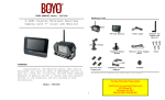
Packing List
Installation
camera power wire connec tion :
These installation instructions do not apply to all vehicles. They
are meant as only as a general guide to big vehicle makes & models.
For specific questions, contact your vehicle manufacturer. Consult
your local motor vehicle laws on the use of this product. Do not
attempt this if you are not knowledgeable with electrical installation
practices.
Digital Wireless
7inch Monitor with DVR
and heavy duty night vision camera
5
1
2
3
4
Rearview
Camera
TFT-LCD
Monitor
Video Cable
Antenna for
camera and
monitor
Suction
Holder
6
Stamping Mount Holder
camera Installation :
Optional:
1. Once you have located the reverse light circuit, you need to
route the power wire to that location. You must securely
fasten the power wire to prevent it from being caught on by
vehicle component such as the trunk hinge. Never route the
cable outside the vehicle.
2m Antenna
for Rearview
Camera
7
8
9
10
Trigger line
Screws
In-Line Wire
Connectors
Grommet
Camera's
power cable
2m Antenna
for Receiver
1. You may mount the camera near the
top of the license plate with screws.
2. Drill six holes: one hole for the
camera's power wire and five holes
for installation of the camera.
The pictures are for reference only, please refer to real subjects.
Red +
reverse lamp
Black -
Structure
SD Card Slot
Antenna
IR LEDs
Notice
Antenna
Lens
The product is not suitable for mini vehicles. For specific
vehicle such as container car or container truck, please
consult your local vehicle garage for installation.
Bracket
7"TFT-LCD
Model:VTC700RQ-2
Link Indicator
Playback Video
Power on/off
Record/stop Video
Version 1.0
Quarter Display Button
Delete file/LCD、TV Switch
Menu
Please read this user manual carefully before using this product.
Failure to understand operation procedures may result in injury.
* The pictures are for reference only, please refer to real subjects.
OK Button
Navigate Button
2.Peel off the backing paper
of the suction holder and
suck it on the front window
of vehicle.
3.Connect power of the
monitor. Reference to the
connection way of the
camera power wire, and
connect the trigger line
correctly. then insert it
into the socket of monitor.
1. Press the POWER button on the monitor for 3 seconds,
the power indicator will illuminate.
After paired
and using
Pairing
A How to install the trigger wire
1. connecting the corresponding female jack first to the monitor male part
2. red/black power wire for the monitor power 9-32V
3. 4 different trigger wires to different camera power source
B Four different color labeled trigger wires
White- camera 1 back-up; Yellow-camera 2 left;
Green-camera 3 right;
Blue- camera 4 toybox inside/front view
If the image does not display on TV, Please check the video
cable is fully inserted into the monitor.
Specifications
2 .While turning left–the triggered left camera image shows on monitor as full screen.
3 .While turning right –the triggered right camera image shows on monitor as full screen.
4 .If neither turning left nor right, the system will be returned as 4ch system.
5 .When back up, no matter right or left camera is triggered, always shows the backup
camera as full screen.
Press the
Value
Imaging Sensor
CMOS
640×480
Horizontal View Angle
85
Transmission Frequency
0 Lux (IR ON)
Minimum Illumination
IR Night Range
FCC Information
This device complies with part 15 of the FCC Rules. Operation
is subject to the following two conditions:
(1) This device may not cause harmful interference.
(2) This device must accept any interference received, including
interference that may cause undesired operation. Changes or
modifications not expressly approved by the party responsible for
compliance could void the user's authority to operate the equipment.
Cautions
● The apparatus shall not be exposed to dripping or splashing
and no objects filled with liquids, such as vases, shall be placed
on the apparatus.
● Turn off the camera/receiver if the system is not in use.
● The camera/receiver can only be completely disconnected from
the mains by unplugging the adapter.
● Do not cut the DC power cable of the apparatus to fit with
another power source.
● Attention should be drawn to the environment aspects of battery
disposal.
3m
Modulating/Demodulating
16QAM,QPSK,BPSK
+12/+24VDC
Waterproof
button to switch between four display modes:
O
ISM 2,400~2,483MHz
Power Supply
IP66
96×52×61 (mm) (Excluding Bracket)
Dimensions (W x D x H)
440g
Approx. Weight
V
Picture display area
2014/03/15/09:30
LCD Screen Type
Picture display area
2014/03/15/09:30
Picture display area
Picture display area
2014/03/15/09:30
Picture display area
2014/03/15/09:30
2014/03/15/09:30
Four pictures
One picture
C2
C2
V
7″TFT-LCD
Transmission Frequency
Receiver
option installation:
For better transmission effect, please connect the optional 2m antenna
to the wireless camera/monitor. The 2m antenna is sucked on the tail of truck.
Items
Total Pixels
V
C Trigger wire functions
1. Turn signal: when turning light signal is pulsed on, left-side camera (camera2)/ right
side camera (camera 3) is activated accordingly.
2. Rear image: when back-up, the rearview camera image will automatically be activated.
3. Trigger video stay: when set left and right side camera, the triggered video will stay
on 3 seconds after pulsing on.
3
Switching to NTSC TV system...
Camera
Trigger wire installation:
ISM 2,400~2,483MHz
800 × 480
Screen Resolution
Video System
NTSC/PAL
Received Sensitivity
-72dBm@QAM, -85dBm@QPSK
Consumption Current (Max.)
650mA
214 ×26×157 (mm)
Dimensions (W×D×H)
V
Picture display area
Picture display area
2014/03/15/09:30
2014/03/15/09:30
C3
Picture display area
Approx. Weight
518g (Excluding Bracket)
EU Environmental Protection
Waste electrical products should
not be disposed of with household
waste. Please recycle where
facilities exist. Check with your
local authority or retailer for
recycling advice.
C3
Picture display area
Picture display area
Power Supply Voltage
DC +9V~32V
Picture display area
2014/03/15/09:30
2014/03/15/09:30
C4
C4
Picture display area
Picture display area
2014/03/15/09:30
2014/03/15/09:30
2014/03/15/09:30
One large picture and
three small pictures
4. Press the
button to enter cyclic mode display. Five cyclic
intervals are available: 5s, 10s, 15s, 20s, and 30s and can
be set under “System”.
4
Unobstructed Effective Range (Matching)
<130m
SD Card
Supports to 32GB
2014/03/15/09:30
One large picture and
three small pictures
5
Crimp tap and then
close lock
2
5. Video are able to be output from the monitor to bigger display
device, such as TV or other screen with a RCA video input.
When the connection is successful, Press the
button to switch
display between the monitor/TV and the receiver.
3. For triggering wires, Monitor will have five related responses as below.
1 .When installed camera and monitor -turning on, Reverse camera displays as full screen.
Insert the wire to
be attached.
3. Wrap In-Line wire connectors over the camera power wire.
2. This equipment has paired successfully out of factory. If not display
image you need to pair again.
Method: screw the metal button of camera back into the upside
hole, Then press the MENU CAMERA PAIRING button to pair in
the receiver. If the pairing is successful, you take away the metal
button and place it into the underside hole.
4.Power on and the power
indicator lights blue, adjust
brightness, contrast and
orientation for image of the
monitor.
Insert the existing
wire to be tapped.
Before drilling those holes, you must check out and make
sure no other components too close to your aiguille. Before
drilling, we strongly recommend you to remove electrical
parts or fuel system behind the vehicle door and clear the
surroundings to avoid unexpected damages.
1
Operations
1.Fastening the suction
holder to the interface
of the monitor back.
Some vehicle may have a hole available to pass the wire
through, you do not need to drill a hole.
Display Mode
Power Indicator
monitor installation:
4.Install the camera with five screws
supplied and adjust the camera to
a proper angle.
3. Insert the power wire of the camera
into the supplied grommet and then
pass the power wire into the vehicle.
Foreword
CONGRATULATIONS. The Rearview Camera, when used as
described, will give you years of dependable service in your car,
truck, RV, or mini-van. We have taken numerous measures in
quality control to ensure that your product arrives in top condition,
and will perform to your satisfaction.
2. The camera is equipped with Reverse Voltage Protection.
please make sure that the Red wire is connected to positive (+)
and the Black wire is connected to negative (-).
AV Output
Power Port
Bracket
Operating Temperature
-10OC~+50OC
Operating Humidity (Max.)
15%~85%RH
The actual transmission range may vary according to the weather,
location, interference and building construction.
All the specifications are subject to minor change without prior notice.
6
7