1
QA65B/QA68B
Extension Base Unit
User's Manual
Thank you for purchasing the Mitsubishi programmable controller
MELSEC-Q series.
Prior to use, please read this and relevant manuals thorougly to fully
understand the product.
MODEL
QA65B-U
MODEL
13JT32
CODE
IB(NA)-0800157-E(1509)MEE
© 2000 MITSUBISHI ELECTRIC CORPORATION
CONDITIONS OF USE FOR THE PRODUCT
(1) Mitsubishi programmable controller ("the PRODUCT") shall be used in
conditions;
i) where any problem, fault or failure occurring in the PRODUCT, if any,
shall not lead to any major or serious accident; and
ii) where the backup and fail-safe function are systematically or
automatically provided outside of the PRODUCT for the case of any
problem, fault or failure occurring in the PRODUCT.
(2) The PRODUCT has been designed and manufactured for the purpose of
being used in general industries.
MITSUBISHI SHALL HAVE NO RESPONSIBILITY OR LIABILITY
(INCLUDING, BUT NOT LIMITED TO ANY AND ALL RESPONSIBILITY
OR LIABILITY BASED ON CONTRACT, WARRANTY, TORT, PRODUCT
LIABILITY) FOR ANY INJURY OR DEATH TO PERSONS OR LOSS OR
DAMAGE TO PROPERTY CAUSED BY the PRODUCT THAT ARE
OPERATED OR USED IN APPLICATION NOT INTENDED OR
EXCLUDED BY INSTRUCTIONS, PRECAUTIONS, OR WARNING
CONTAINED IN MITSUBISHI'S USER, INSTRUCTION AND/OR SAFETY
MANUALS, TECHNICAL BULLETINS AND GUIDELINES FOR the
PRODUCT.
("Prohibited Application")
Prohibited Applications include, but not limited to, the use of the PRODUCT
in;
• Nuclear Power Plants and any other power plants operated by Power
companies, and/or any other cases in which the public could be
affected if any problem or fault occurs in the PRODUCT.
• Railway companies or Public service purposes, and/or any other cases
in which establishment of a special quality assurance system is
required by the Purchaser or End User.
• Aircraft or Aerospace, Medical applications, Train equipment, transport
equipment such as Elevator and Escalator, Incineration and Fuel
devices, Vehicles, Manned transportation, Equipment for Recreation
and Amusement, and Safety devices, handling of Nuclear or
Hazardous Materials or Chemicals, Mining and Drilling, and/or other
applications where there is a significant risk of injury to the public or
property.
A-1
Notwithstanding the above, restrictions Mitsubishi may in its sole discretion,
authorize use of the PRODUCT in one or more of the Prohibited
Applications, provided that the usage of the PRODUCT is limited only for
the specific applications agreed to by Mitsubishi and provided further that
no special quality assurance or fail-safe, redundant or other safety features
which exceed the general specifications of the PRODUCTs are required.
For details, please contact the Mitsubishi representative in your region.
A-2
REVISIONS
*The manual number is given on the bottom right of the cover.
Print date
*Manual number
September 2015
IB(NA)-0800157-E
Revision
Combine the Japanese manual (IB-0800157)
with the English manual (IB-0800158).
This manual confers no industrial property rights or any rights of any other kind,
nor does it confer any patent licenses. Mitsubishi Electric Corporation cannot be
held responsible for any problems involving industrial property rights which may
occur as a result of using the contents noted in this manual.
© 2000 MITSUBISHI ELECTRIC CORPORATION
A-3
CONTENTS
1. OVERVIEW ................................................................................................... 1
1.1
Overview ............................................................................................... 1
1.2
Included Parts ....................................................................................... 1
2. SYSTEM CONFIGURATION ......................................................................... 2
2.1
System Configuration............................................................................ 2
2.2
List of configuration devices.................................................................. 3
3. SPECIFICATIONS.......................................................................................... 5
4. PART NAMES AND SETTING ....................................................................... 6
4.1
Part Names ........................................................................................... 6
4.2
Extension Stage Number Setting .......................................................... 7
5. MOUNTING AND INSTALLATION................................................................. 8
5.1
Module Installation ................................................................................ 8
5.2
Precautions for installing base unit ....................................................... 9
5.3
Installation and removal of modules.................................................... 12
6. EXTERNAL DIMENSIONS........................................................................... 14
A-4
1. OVERVIEW
1.1
Overview
This User's Manual describes the specifications, configuration devices,
names and settings of each part, and mounting and installation of the
QA65B extension base unit, QA68B extension base unit (hereinafter,
QA6B).
Refer to the QCPU User's Manual(Hardware Design, Maintenance and
Inspection) SH-080483ENG enclosed with the main base unit for the
matters not described in this manual, such as the QA6B safety
precautions and general specifications.
1.2
Included Parts
This section describes parts included with this module.
Product
Type
Extension base unit
Quantity
QA6B
1
I/O number seal
1
This manual
1
1
2. SYSTEM CONFIGURATION
2.1
System Configuration
The system configuration and precautions for using the QA6B
extension base unit are described in this section.
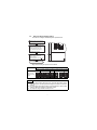
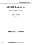
(1)
Extension base unit connection order
When using the Q5B/Q6B, QA1S6B and QA6B together,
connect from the unit closest to the main base unit in the order of
Q5B/Q6B, QA1S6B and QA6B.
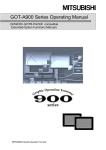
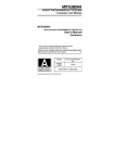
(2)
Setting order of the expansion stage numbers for expansion base
units
Expansion base units require the setting of the expansion stage
numbers (1 to 7) using the stage setting connector.
Assign the expansion stage numbers starting from 1 to 7 to the
expansion base units counting from the one which is connected to
the main base unit.
Setting of
extension stage
Stage setting
connector
QCPU
0 1 2 3 4 5 6 7
Q38B
Main base unit
Q68B
Extension base unit for module
installation corresponding to the
Q series
(Connect the Q5 B/Q6 B with
the main base unit and the last
Q5 B/Q6 B.)
QA1S68B
Extension base unit for module
installation corresponding to the
AnS series
(Connect the QA1S6 B with
the main base unit and the last
Q5 B/Q6 B, or QA1S6 B.)
QA68B
Extension base unit for module
installation corresponding to the A
series
(Connect the QA6 B with the
main base unit and the last Q5 B
/Q6 B/QA1S6 B, or QA6 B.)
8 9 10 11 12 13 14 15
QCPU
1
QCPU
16 17 18 19 20 21 22 23
2
QCPU
24 25 26 27 28 29 30 31
3
2
2.2
List of configuration devices
The following table lists the mountable modules on the QA6B
extension base unit.
Type
Remarks
Power module
Module
A61P, A61PN, A62P, A63P, A68P, A61PEU, A62PEU
Input module
AX10, AX11, AX11EU, AX20, AX21, AX21EU, AX31,
AX31-S1, AX40, AX41, AX41-S1, AX42, AX42-S1,
AX50-S1, AX60-S1, AX70, AX71, AX80, AX80E, AX81,
AX81-S1, AX81-S2, AX81-S3, AX81B, AX82
Output module
AY10, AY10A, AY11, AY11A, AY11E, AY11AEU,
AY11EEU, AY13, AY13E, AY13EU, AY15EU, AY22,
AY23, AY40, AY40A, AY41, AY42, AY42-S1, AY42-S2,
AY42-S3, AY42-S4, AY50, AY51, AY51-S1, AY60,
AY60S, AY60E, AY70, AY71, AY72, AY80, AY81,
AY82EP
I/O module
A42XY, AH42
High-speed counter
module
AD61, AD61S1
*1
Analog-digital conversion
A68AD, A68AD-S2, A68ADN, A616AD
module
Digital-analog
conversion module
A62DA, A62DA-S1, A68DAV, A68DAI-S1, A616DAV,
A616DAI
Temperature-digital
conversion module
A68RD3, A68RD3N, A68RD4, A68RD4N, A616TD,
A60MX, A60MXR, A60MXRN, A60MXT, A60MXTN
Interrupt module
AI61, AI61-S1
*2
AD70, AD70D, AD71, AD71S1, AD71S2, AD71S7,
AD72
AD75P1-S3, AD75P2-S3, AD75P3-S3, AD75M1,
AD75M2, AD75M3
*1
MELSECNET/MINI-S3
master module
AJ71PT32-S3, AJ71T32-S3
*1
Intelligent
communication module
AD51, AD51E, AD51H, AD51-S3, AD51E-S3,
AD51H-S3
*2
PC fault detection
module
Positioning module
AS91
MELSEC-I/OLINK
module
AJ51T64
B/NET module
AJ71B62-S3
Blanking module
AG60
Dummy module
AG62
A-A1S conversion
adapter
A1ADP-XY, A1ADP-SP
*3
3
*1 The dedicated commands used in the QnA and A Series program cannot be used with the
Q mode CPU.
Replace these with FROM/TO commands.
*2 There is a limit to the number of mountable modules.
Module
Type
number of mountable
Intelligent communication
module
AD51, AD51E, AD51-S3, AD51E-S3,
AD51H, AD51H-S3
6 *4
Interrupt module
AI61, AI61-S1
1 *5
*3 The AnS series modules (equivalent ones to the modules listed in the table) also can be
used by using the A-A1S conversion adapter.
(Example: A68AD A1S68AD)
For precautions on the module replacement, refer to the manual for the A-A1S conversion
adapter.
*4 In combined use of the QA1S6 B and QA6 B, up to 6 intelligent communication modules
can be installed.
*5 Only one interrupt module is valid which can be chosen from QI60, A1SI61, AI61 or AI61S1.
4
3. SPECIFICATIONS
The QA6B performance specifications are given below.
Type
Item
Number of I/O modules connected
Applicable modules
QA65B
QA68B
5
8
A series module
5VDC internal current consumption
0.117A
0.117A
Weight
1.60kg
2.00kg
5
4. PART NAMES AND SETTING
The names of and settings for each QA6B part are explained in this
section.
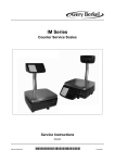
4.1
Part Names
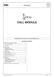
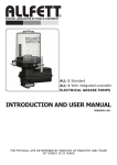
The names of each QA6B part are explained below.
3)
5) 6)
4)
7)
1)
2)
QA68B
5) 6)
No.
1)
2)
3)
Name
Expansion cable
connector
Base cover
Stage number setting
connector
4)
Module connector
5)
Module fixing hole
Screw hole for
fastening modules
Base module
installation hole
6)
7)
Application
A connector for signal transmission with the basic base module
or the other expansion base module. Connects the expansion
cable. Do not remove the supplied connector cover.
PCB surface protection cover.
A used to set the stage numbers of the expansion base
modules. Refer to section 4.2 for the setting procedure.
Connector for mounting power supply unit, input/output unit and
special function module.
Mount the dustproof connector cover, blank cover unit (AG60)
or dummy unit (AG62) on the connector in the spare spaces
with module connected.
Cut out to accept projection and hook at rear of modules.
A screw hole used for fastening a module to the base.
(M4 screw)
A hole used for mounting the base module to a panel such as
a control panel.
6
4.2
Extension Stage Number Setting
The method of setting the QA6B stages is explained below.
Remove the base cover from the
expansion base module.
Select the stage number from 1 to
7 in the connector (PIN1) loaction
between the expansion cable
connectors IN and OUT. Then,
insert a connector pin into the
approprate stage number.
CON11 CON10
PIN1
Reattach the base cover to the
expansion base module and
fasten the screws.
(Tightening torque: 36 to 48N cm)
Completion
Stage number setting for expansion base modules
Extension stage number setting
1st stage 2nd stage 3rd stage 4th stage 5th stage 6th stage 7th stage
Stage number
setting connector
setting
PIN1
PIN1
PIN1
PIN1
PIN1
PIN1
PIN1
POINT
(1) To set the stage number setting connector, select the appropriate number
from 1 through 7 in ascending order according to the number of expansion
modules.
(2) Do not assign the same stage number to several modules or skip any stage
numbers. Otherwise, improper I/O operation results.
(3) The expansion stage number is factory-set to 1.
7
5. MOUNTING AND INSTALLATION
5.1
Module Installation
This section describes the precautions to handle the CPU, I/O, special
function, power supply, and base module.
(1)
Do not drop or apply a strong impact to the module housing,
memory card, terminal block connectors, and pin connectors.
(2)
Do not remove the PC board of the modules from housing.
Otherwise, malfunctions may result.
(3)
When using the expansion base module QA6 B, be sure to install
the power supply module.
Although the module may work without the power supply module
under light load, stable operation is not guaranteed.
(4)
Limit the tightening torque for the module installation screws and
terminal block screws within the following range:
Location of screw
Tightening torque range
I/O module terminal block installation screw (M3)
A series module installation screw (M4)
36 to 48 N•cm
78 to 118 N•cm
I/O module terminal screw (M4)
Power supply module terminal screw (M4)
98 to 137 N•cm
8
5.2
Precautions for installing base unit
(1)
Unit installation position
Indicates the panel top,wiring
duct, or any assembly.
80mm or more
QA6 B extention base
Q3 B basic base
*1
Parallel mounting
Indicates the panel top,wiring
duct, or any assembly.
Basic base
Extention base
80mm or more
80mm or more
Duct
(max. 50mm)
*2
*1
Serial mounting
9
*1 When link module is not used : 50mm or more
When using 4.5mm optical fiber cable : 100mm or more
When using a coaxial cable : 100mm or more
When using 8.5mm optical fiber cable : 130mm or more
*2 20mm or more when connecting extension cable without removing adjacent modules.
(2)
Module installing position
(a) Install the PC in the following position to ensure ventilation for
heat radiation.
(b) Do not install the PC in the following positions.
Vertical position
Horizontal position
10
(3)
Install the base module on a flat surface.
When the base module is installed on an uneven surface, the PC
board may be strained, resulting in malfunction.
(4)
Do not install the PC close to a vibration source such as a large
electromagnetic contactor or no-fuse breaker. Install the PC to the
separate panel or isolate it as far as possible.
(5)
Provide the following distances between the PC and devices
(contactor or relay) to avoid the influence of radiation noise or heat.
• Device installed in front of the PC: 100mm or more
• Device installed on either side of the PC: 50mm or more
50mm or more
100mm
or more
50mm or more
Contactor
relay,etc
11
5.3
Installation and removal of modules
This section explains the installation and removal procedures of the
power supply module, CPU module, I/O module, special function
module, etc to and from the base unit.
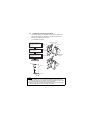
(1)
Installation of module
Module fixing hole(A)
Insert the two module fizing
projections (two) into the
module fixing hole (B) in the
base unit.
Base unit
Module unit
Load the module into the
base unit by pushing it in the
direction of arrow.
Check if the hook of module
is securely inserted in the
module fixing hole (A) in the
base unit.
Hook
Module
connector
Module fixing hole(B)
Two module
fixing
projections
Complated
Base unit
Module
Module mounting screw
(M4 0.7 12)
POINT
(1) To fix the module, be sure to insert the module fixing projection into the
module fixing hole (B). If the module is forcibly fixed without insertion, the
pins in the module connector may be bent or damaged.
(2) When the base unit is used at locations where there are especially large
vibration and/or shock, screw the module to the base.
12
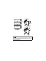
(2)
Removal of module
Base unit
Hold the module with both
hands and push the hook
latch at the top of module.
While pushing the hook latch,
pull the module toward you.
Push
Module fixing hole(A)
hook
Module
connector
Module
Lift upwards and remove the
module fixing projections
from the module fixing hole
(B).
Module
fixing
hole (B)
Completed
POINT
To remove the module, be sure to disengage the hook from the module fixing
hole (A) and then remove the module fixing projections from the module fixing
hole (B). If the module is forcibly removed, the hook or module fixing
projections will be damaged.
13
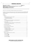
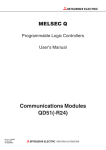
6. EXTERNAL DIMENSIONS
The external dimensions of the QA6B are shown below.
(1)
The external dimensions of the QA68B
4- 6 installation hols
(M5 mounting screw)
2 9-M4 screws
(for mosule installation)
Base cover
250
200 0.3
Hand
hold
QA68
446 0.3
46.6
10
466
Unit: mm
Base cover
The external dimensions of the QA65B
2 6-M4 screws
(for mosule installation)
200 0.3
Hand
hold
4- 6 installation hols
(M5 mounting screw)
250
(2)
QA65B
332 0.3
46.6
10
352
Unit: mm
14
WARRANTY
Mitsubishi will not be held liable for damage caused by factors found not to be the cause of
Mitsubishi; machine damage or lost profits caused by faults in the Mitsubishi products; damage,
secondary damage, accident compensation caused by special factors unpredictable by
Mitsubishi; damages to products other than Mitsubishi products; and to other duties.
Country/Region Sales office/Tel
Country/Region Sales office/Tel
USA
Mitsubishi Electric Automation lnc.
500 Corporate Woods Parkway, Vernon
Hills, IL 60061, USA
Tel : +1-847-478-2100
South Africa
CBI-Electric.
Private Bag 2016, ZA-1600 Isando,
South Africa
Tel : +27-11-977-0770
Brazil
MELCO-TEC Representacao Comercial
e Assessoria Tecnica Ltda.
Av. Paulista, 1439, cj74, Bela Vista,
Sao Paulo CEP: 01311-200-SP Brazil
Tel : +55-11-3146-2200
China
Mitsubishi Electric Automation (China) Ltd.
No.1386 Hongqiao Road, Mitsubishi
Electric Automation Center, Changning
District, Shanghai, China
Tel : +86-21-2322-3030
Germany
Mitsubishi Electric Europe B.V. German
Branch
Gothaer Strasse 8, D-40880 Ratingen,
Germany
Tel : +49-2102-486-0
Taiwan
Setsuyo Enterprise Co., Ltd.
6F., No.105, Wugong 3rd Road, Wugu
District, New Taipei City 24889, Taiwan,
R.O.C.
Tel : +886-2-2299-2499
UK
Mitsubishi Electric Europe B.V. UK Branch
Travellers Lane, Hatfield, Hertfordshire,
AL10 8XB, UK.
Tel : +44-1707-27-6100
Korea
Italy
Mitsubishi Electric Europe B.V. Italian
Branch
Viale Colleoni 7-20864 Agrate Brianza
(Milano), Italy
Tel : +39-039-60531
Mitsubishi Electric Automation
Korea Co., Ltd.
3F, 1480-6, Gayang-Dong, Gangseo-Gu,
Seoul, 157-200, Korea
Tel : +82-2-3660-9530
Singapore
Mitsubishi Electric Europe B.V. Spanish
Branch
Carretera de Rubi 76-80.AC.420, E-08190
Sant Cugat del Valles (Barcelona), Spain
Tel : +34-93-565-3131
Mitsubishi Electric Asia Pte, Ltd. Industrial
Division
307, Alexandra Road, Mitsubishi Electric
Building, Singapore, 159943
Tel : +65-6470-2308
Thailand
Mitsubishi Electric Automation (Thailand)
Co., Ltd.
Bang-Chan Industrial Estate No.111
Soi Serithai 54,
T.Kannayao, A.Kannayao, Bangkok
10230 Thailand
Tel : +66-2906-3238
Indonesia
P. T. Autoteknindo Sumber Makmur
Muara Karang Selatan, Block A / Utara
No.1 Kav. No. 11,
Kawasan Industri Pergudangan,
Jakarta-Utara 14440, P.O, Box 5045,
Indonesia
Tel : +62-21-663-0833
India
Mitsubishi Electric India Pvt. Ltd.
2nd Floor, Tower A & B, Cyber Greens,
DLF Cyber City, DLF Phase-III,
Gurgaon-122002 Haryana, India
Tel : +91-124-463-0300
Australia
Mitsubishi Electric Australia Pty. Ltd.
348 Victoria Road PO BOX11,
Rydalmere, N.S.W 2116, Australia
Tel : +61-2-9684-7777
Spain
France
Mitsubishi Electric Europe B.V. French
Branch
25, Boulevard des Bouvets, F-92741
Nanterre Cedex, France
Tel : +33-1-5568-5568
Czech Republic Mitsubishi Electric Europe B.V.-o.s.Czech
office
Avenir Business Park, Radicka 751/113e,
158 00 Praha5, Czech Republic
Tel : +420-251-551-470
Poland
Mitsubishi Electric Europe B.V. Polish
Branch
ul. Krakowska 50, 32-083 Balice, Poland
Tel : +48-12-630-47-00
Russia
Mitsubishi Electric Europe B.V. Russian
Branch St.Petersburg office
Piskarevsky pr. 2, bld 2, lit "Sch", BC
"Benua", office 720; 195027,
St. Petersburg, Russia
Tel : +7-812-633-3497
HEAD OFFICE : TOKYO BUILDING, 2-7-3 MARUNOUCHI, CHIYODA-KU, TOKYO 100-8310, JAPAN
NAGOYA WORKS : 1-14, YADA-MINAMI 5-CHOME, HIGASHI-KU, NAGOYA, JAPAN
When exported from Japan, this manual does not require application to the Ministry
of Economy, Trade and Industry for service transaction permission.
Specifications subject to change without notice.