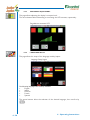
1
Manuale Istruzioni - Instruction Manual
Manuel d’Instructions - Bedienungsanleitung
Manual de instrucciones
PROFESSIONAL POWER QUALITY
ANALYZER & DATALOGGER
Rel.2° 02/2007 Eng.
General Index
General Index
1 GENERAL INFORMATION ...................................................................... 1-3
1.1 INTRODUCTION .................................................................................... 1-3
1.1.1
POWER QUALITY..................................................................... 1-3
1.2 INSTRUMENT PURPOSE ........................................................................ 1-4
1.3 CERTIFICATE OF CONFORMITY ............................................................ 1-5
1.4 WARRANTY AND LIMITED LIABILITY.................................................. 1-6
1.5 INSTRUCTION MANUAL ....................................................................... 1-7
1.5.1 MANUAL STRUCTUREL............................................................... 1-7
1.5.2 SYMBOLS, ABBREVIATIONS AND TERMINOLOGY USED......... 1-7
1.5.3 GLOSSARY ..................................................................................... 1-8
1.6 GENERAL WARNINGS FOR USE .......................................................... 1-9
2 SAFETY .......................................................................................................... 2-3
2.1 GENERAL INFORMATION...................................................................... 2-3
2.2 SIGNALS ................................................................................................ 2-4
3 PRELIMINARY INSTRUCTIONS ....................................................................... 3-3
3.1 INSTRUMENT UNPACKING ................................................................... 3-3
3.2 INTERFACES AND CONNECTIONS ...................................................... 3-4
3.3 CONNECTION TO THE SYSTEM ........................................................... 3-6
3.3.1 LOW VOLTAGE CONNECTION ............................................... 3-6
3.3.2 MEDIUM VOLTAGE CONNECTION ......................................... 3-8
3.4 FIRST TURN ON ..................................................................................... 3-9
4 OPERATING INSTRUCTIONS ............................................................... 4-3
4.1 GENERAL INFORMATION...................................................................... 4-3
4.1.1
PUSHBUTTONS, CHECKBOXES, EDITBOXES, LISTBOXES ... 4-4
4.2 SYSTEM STRUCTURE.............................................................................. 4-6
4.2.1 STATUS BAR.............................................................................. 4-16
4.3 MEASUREMENT PAGES .......................................................................... 4-17
4.3.1 METER ....................................................................................... 4-19
4.3.2 SCOPE ....................................................................................... 4-20
4.3.3 HARMONICS/ INTERHARMONICS ........................................ 4-21
4.3.4 FLICKER ..................................................................................... 4-22
4.3.5 PHASOR .................................................................................... 4-23
4.3.6 TRANSIENT............................................................................... 4-26
4.3.7 DIPS & SWELLS (& INTERRUPTIONS)..................................... 4-28
4.3.8 EN 50160 ................................................................................... 4-32
4.4 DATALOGGER ......................................................................................... 4-37
4.4.1 CAMPAIGN START AND STOP ................................................ 4-40
4.5 MEASUREMENT SETUP PAGES .............................................................. 4-44
4.5.1 VOLTAGE SETUP ....................................................................... 4-45
4.5.2 CURRENT SETUP ..................................................................... 4-46
4.5.3 AUXILIARY CHANNEL SETUP ................................................. 4-47
4.5.4 COUNTER RESET ..................................................................... 4-47
4.6 INSTRUMENT SETUP PAGES .................................................................. 4-48
4.6.1 DATE AND TIME SETUP ........................................................... 4-49
4.6.2 COMPACT FLASH SETUP ......................................................... 4-49
4.6.3 COMMUNICATION INTERFACE SETUP .................................. 4-50
4.6.4 CONTRAST ADJUSTMENT ...................................................... 4-50
4.6.5 LANGUAGE SETUP ................................................................... 4-51
4.6.6 SYSTEM UPGRADE SETUP ....................................................... 4- 52
General Index
4.7
INSTRUMENT USE .................................................................................. 4-53
4.7.1
CONNECTION TO THE SYSTEM ............................................. 4-53
4.7.2
INSTRUMENT START UP.......................................................... 4-56
4.7.3
CHECK OF THE PROPER CONNECTION TO THE SYSTEM .. 4-57
4.7.4
EXECUTION OF THE MEASURING CAMPAIGNS .................. 4-59
4.7.5
INSTRUMENT TURNING OFF ................................................. 4-60
4.7.6
ANALYSIS OF THE DATA MEASURED ..................................... 4-60
5 MAINTENANCE .......................................................................................... 5-3
5.1 INSTRUMENT STORAGE ........................................................................ 5-3
6 TECHNICAL SPECIFICATIONS ............................................................. 6-3
6.1 INSTRUMENT FEATURES ....................................................................... 6-3
6.1.1
GENERAL SPECIFICATIONS ..................................................... 6-3
6.1.2
INPUT CHANNELS ................................................................... 6-4
6.1.3
ENVIRONMENTAL .................................................................... 6-5
6.1.4
REFERENCE STANDARDS ........................................................ 6-5
6.2 ACCESSORY FEATURES .......................................................................... 6-5
6.2.1 FLEXIBLE CLAMPS .................................................................... 6-5
6.2.2 VOLTAGE CONNECTION CABLES .......................................... 6-5
6.2.3 POWER SUPPLY ........................................................................ 6-6
6.2.4 BATTERIES................................................................................. 6-6
6.3 ELECTRICAL PARAMETERS MEASURED ............................................... 6-7
7 ACCESSORIES .............................................................................................. 7-3
General Index
General Index
Chapter 1
General Information
Index chapter 1
1 GENERAL INFORMATION ...................................................................... 1-3
1.1 INTRODUCTION .................................................................................... 1-3
1.1.1
POWER QUALITY..................................................................... 1-3
1.2 INSTRUMENT PURPOSE ........................................................................ 1-4
1.3 CERTIFICATE OF CONFORMITY ............................................................ 1-5
1.4 WARRANTY AND LIMITED LIABILITY.................................................. 1-6
1.5 INSTRUCTION MANUAL ....................................................................... 1-7
1.5.1
MANUAL STRUCTURE ............................................................ 1-7
1.5.2
SYMBOLS, ABBREVIATIONS AND TERMINOLOGY USED..... 1-7
1.5.3
GLOSSARY ................................................................................. 1-8
1.6 GENERAL WARNINGS FOR USE .......................................................... 1-9
1-2
1 - General information
1
GENERAL INFORMATION
1.1
INTRODUCTION
This manual is intended to describe the technical and functional features of the Jupiter/Jupiter Plus Power Quality Analyser, besides providing interesting indications on
the importance of Power Quality.
Instructions, drawings and documentation included in this Instruction Manual are of a
confidential technical nature and are a property of Elcontrol Energy Net S.p.A. Any
reproduction thereof, either integral or partial, is forbidden.
Any names and trademarks mentioned in this document are an exclusive property of
the respective Companies.
1.1.1
POWER QUALITY
Jupiter/Jupiter Plus is a three-phase and single-phase instrument designed for engineers
who need to detect the different types of interferences on the electrical network
(voltage fluctuations, frequency variations, presence of harmonics/interharmonics,
voltage unbalances, interruptions, etc.).
Jupiter/Jupiter Plus further allows the analysis of the power quality.
Power quality is essential to ensure proper operation of the electrical and electronic
devices used in industrial and civil installations.
Besides being harmful for such devices, in the field of industrial production a poor
power quality is also very harmful from the economic point of view.
Power quality features are set out in the CEI EN 50160 technical standard.
On his/her initiative or as a request to third parties, the customer may install Jupiter
as Power Quality Analyser.
Customers with specific needs may also carry out highly detailed measuring campaigns, thanks to the possibility of data to be stored to a removable COMPACT FLASH
memory.
The campaigns’ analysis is then performed by the PQStudio PC software, which can
make a complete and detailed analysis.
This instrument can store up to 9350 events, both in voltage and in current, and record
all the waveform samples.
The events can also be read on the PC using the PQStudio software, which displays
them in a chronological order and shows the relevant waveforms.
1 - General information
1-3
1.2
INSTRUMENT PURPOSE
Elcontrol Energy Net S.p.A. has designed and built this product making use of the
know-how acquired in 50 years of experience as market leader in power parameter
measurement and consumption optimisation.
Jupiter/Jupiter Plus is an innovative power measuring instrument of exceedingly high
technological content that at the same time is easy and intuitive to use.
1-4
1 - General information
1.3
CERTIFICATE OF CONFORMITY
Declaration of conformity for:
JUPITER and Jupiter Plus portable three-phase power quality analyzer
Manufacturer:
Elcontrol Energy Net S.p.A.
Via Vizzano, 44
40044 Sasso Marconi - Loc. Pontecchio (BO) - Italy
Based on the tests carried out, the product is in conformity with:
Directives 89/336/EEC and 2004/108/EC (Electromagnetic Compatibility)
Directive 73/23/EEC (Low Voltage)
Reference standards used:
CEI EN 61010-1 (second edition)
Safety requirements for electrical equipment for measurement, control and laboratory
use
Part 1: General requirements
Identical to: IEC 61010-1:2001-02 and EN 61010:2001-03
CEI EN 61326 (first edition)
Electrical equipment for measurement, control and laboratory use – EMC requirements
Identical to: IEC 61326-1:1997-03 and EN 61326-1:1997-04; EN 61326-1 Ec:1998-01
CEI EN 61326/A1
Equipment for measurement, control and laboratory use – EMC requirements
Identical to IEC 61326-1/A1:1998-05 and EN 61326/A1:1998-06; EN 61326-1 Ec:199809
CEI EN 61326/A2
Equipment for measurement, control and laboratory use – EMC requirements
Identical to IEC 61326-1/A2:2000-08 and EN 61326/A2:2001-05
CEI EN 61326/A3
Equipment for measurement, control and laboratory use – EMC requirements
Identical to IEC 61326:2002-02 (Annex E & F); IEC 61326/Ec1:2002-07 and EN 61326/
A3:2003-12
Type tests were performed on the typical configuration.
Conformity to the above-mentioned tests is indicated by the
the instrument
mark placed on
The equipment is further compliant with the 2002/95/EC Directive
(RoHS).
Information regarding disposal
Jupiter/Jupiter Plus is an electrical apparatus and, as such, must be handled according
to the Directives 2002/96/EC and subsequent modification 2003/108/EC, at the
end of its lifetime.
The
mark placed on the plastic case of the instrument therefore indicates
that the product must not be thrown away in the rubbish, but instead disposed of at
a special collection and recycling centre.
1 - General information
1-5
1.4
WARRANTY AND LIMITED LIABILITY
Every Jupiter is tested and calibrated in conformity with strict controls and processes
that guarantee it is without material defects and errors in craftsmanship, ensured by
application of the Quality Management System in compliance with the UNI EN ISO
9001:2000 (Vision 2000) standard.
The period of warranty is 3 years on hardware parts of the analyser considered defective and 1 year on the accessories (amperometric sensors, cables, memory, etc.)
and parts that may require replacement.
This period commences on the date the instrument is calibrated.
The warranty covering any operational problems of the software inside the analyser
(firmware) is not given unless otherwise communicated by the manufacturer.
The warranty is valid only for the first purchaser or for the end customer of an Authorised Elcontrol Energy Net S.p.A. Dealer, and does not cover expendable or
perishable materials (e.g. batteries, plastics, etc.).
Neither does the warranty cover any product or accessory that, in the opinion of
the manufacturer, has been used improperly, or has been deliberately or accidentally
altered or damaged.
The warranty is therefore also forfeited in the case of damage to the instrument, accessories, equipment, or systems, or injuries to people, deriving from incorrect electrical
connection, overvoltage, improper use, etc.
No damages caused by the product remaining unused or by third parties shall be
acknowledged.
Elcontrol Energy Net S.p.A. declines all responsibility for direct, indirect, accidental
or consequent damages or losses (including the loss of data) caused by violations of
the warranty or by contractual or penal clauses, torts, claims, etc.
Elcontrol Energy Net S.p.A. warrants that the “PQ Studio” CD-Rom included
in the supply will operate correctly for 30 days, and that it has been masterized on
first-rate, non-defective optical supports.
The manufacturer does not guarantee that said software is completely operationally
error-free, and that it is perfectly compatible with any PC.
Elcontrol Energy Net S.p.A. declines all responsibility for any damages caused
by product transport.
The defective product must always be returned directly to the manufacturer or authorised importer/distributor of your country CARRIAGE FREE, subject to prior
authorisation of Elcontrol Energy Net S.p.A.
Repair under warranty must be accompanied by a proof-of-purchase document.
1-6
1 - General information
1.5
INSTRUCTION MANUAL
The Instruction Manual should be carefully stored and should be provided with the
equipment in any transfers of ownership it may undergo during its life cycle.
The hard copy manual should be kept away from humidity and heat.
No parts of the manual should be removed, changed or torn.
The contents of this Instruction Manual are to be considered susceptible to changes
since Elcontrol Energy Net S.p.A. reserves the right to modify the characteristics, functionalities and screens of the instrument at any time and without prior notification.
The figures contained herein are therefore to be considered indicative, and may not
perfectly correspond with reality.
1.5.1
MANUAL STRUCTURE
This Instruction Manual is divided into the following chapters:
Chapter 1 - General information.
Provides general information on the Instruction Manual.
Chapter 2 - Safety.
Provides primary information for a safe use of Jupiter in order to prevent
hazards for the operator’s safety or damages to the instrument.
Chapter 3 - Preliminary instructions.
Provides information for the first use of the instrument.
Chapter 4 - Operating instructions.
Describes all the instrument functions and the operations for a proper
and safe use thereof.
Chapter 5 - Maintenance.
Provides instructions for a proper instrument storage.
Chapter 6 - Technical specifications.
Detailed description of Jupiter’s features and functions.
Chapter 7 - Accessories.
List of recommended and approved accessories for Jupiter and Jupiter Plus.
1.5.2
SYMBOLS, ABBREVIATIONS AND TERMINOLOGY USED
1.5.2.1 Symbols used in the Manual
Important note or instruction
Carefully read the instructions next to the symbol.
This symbol may also be found close to equipment components for which
reading the User Manual is recommended.
1.5.2.2 Symbols on the instrument
Only this symbol may be found on the instrument.
For the components close to the symbol, reading this User Manual is
recommended.
1 - General information
1-7
1.5.2.3 Abbreviations and initials used in the Manual
Abbreviations used in the Manual
Chap.
Sect.
Tab.
Fig.
= Chapter
= Section
= Table
= Figure
Technical abbreviations
RMS
LV
MV
VT
CT
= Effective value (Root Mean Square)
= Low Voltage
= Medium Voltage
= Voltage Transformer
= Current Transformer
1.5.3
GLOSSARY
Operator or User:
Specialised technician having the skills required to use the Jupiter/Jupiter Plus Power
Quality Analyser.
System:
The item (electrical board, supply line, etc.) to be measured using Jupiter.
Instrument or equipment:
These terms may be used to refer to the Jupiter/Jupiter Plus Power Quality Analyser.
Operative System:
Complete set of pages of the operator/Jupiter/Jupiter Plus communication interface.
Page or Screen:
These terms are used to refer to each Display that may be shown on the Jupite/Jupiter
Plus screen.
Menu:
Set of system pages relating to a specific topic.
Key:
An element of the Jupiter/Jupiter Plus alphanumerical keyboard which, when pressed,
enables access to the corresponding function.
Measuring campaign:
Data and/or event recording that can then be analysed (data logging).
1-8
1 - General information
1.6
GENERAL WARNINGS FOR USE
Read the following general instructions to ensure proper instrument use and rou
maintenance:
• The instrument should only be powered by battery or using the external power
supply included in the supply kit, connected to a mains having the following characteristics:
Voltage: 100-240 VAC
Frequency: 50-60 Hz
• Use only rechargeable NiMh type AA - 2300mAh batteries.
• The batteries recharge automatically when the instrument is connected to the power
supply.
Time required for full recharge (with batteries fully low);
• 10 hours maximum (with instrument on)
• 20 hours maximum (with instrument off)
• When the system is battery-powered, this is shown in the status bar (see sect.
4.2.1).
• Every time the instrument is battery-powered, after 3 minutes from the last pressure
of any key, the system switches to POWER SAVING mode.
In this mode, the display backlight is switched off, thus allowing longer operating
life.
A special LED, located on the front side of the instrument, indicates that the instrument is on (see sect. 3.2).
• When the instrument is battery-powered, and the voltage level of both battery packs
drops below the minimum threshold required for proper operation, the instrument
switches off automatically. Recharge the batteries.
• In the event of battery malfunctioning or reduced life, replace the ENTIRE battery
pack.
• Replace the battery pack with instrument off and without measurement connections.
• The on-screen graphical display is ensured within a temperature range from 0 to
+50°C.
• Avoid any pressures on the screen.
• Clean the screen with a soft and clean cloth.
Do not use any detergents.
• NEVER remove or insert the Compact Flash memory while the instrument is on.
1 - General information
1-9
1 - 10
1 - General information
Chapter 2
Safety
Index chapter 2
2 SAFETY .......................................................................................................... 2-3
2.1 GENERAL INFORMATION...................................................................... 2-3
2.2 SIGNALS ................................................................................................. 2-4
2-2
2 - Safety
2
SAFETY
Jupiter/Jupiter Plus is compliant with the IEC EN 61010-1 standard as 600V Cat. III
- Pollution rating 2.
The instrument must be used as indicated in this Instruction Manual.
Improper use of the analyser could compromise the instrument’s safety-characteristics.
2.1
GENERAL INFORMATION
So as to prevent fires and/or electrocutions, it is very important that the operator
follows these instructions:
•
•
•
•
•
•
•
Carefully read this Instruction Manual before using Jupiter.
The instrument is for expert users only. Do not use it without having the ne
cessary technical and electrical safety-related skills.
Use only the accessories supplied with the instrument or type-approved.
Do not use Jupiter in environments where there are explosive gases or va
pours.
It is absolutely forbidden to use Jupiter for any application other than that
for which it has been designed and built.
Do not apply voltages higher than the operating voltages of the instrument.
Connect the instrument only as indicated.
The
symbol placed on some points of the instrument indicates that important information about the devices close to the symbol is contained in the Instruction
Manual.
WARNING
Elcontrol Energy Net S.p.A. declines all responsibility for direct or
indirect, accidental or consequent injuries suffered by the equipment,
user or third parties caused by improper use of the instrument.
2 - Safety
2-3
2.2
SIGNALS
Safety-related symbols or signals may be found in this Instruction Manual or in the
departments where Jupiter is used.
The main prohibition, hazard and obligation symbols are summarised to this end.
Only part of the following symbols relates directly to the activity of the Jupiter/Jupiter
Plus User.
The Operator and any Assistants thereof shall make sure that the primary safety rules
(use of appropriate clothing, prohibition to smoke, etc.) are observed in the departments or areas where the activities are carried out.
PROHIBITION Signals
GENERAL prohibition
The presence of this symbol indicates the prohibition to touch,
tamper or change the adjusting devices, unless authorised in
advance by the Manufacturer.
Do not SMOKE
Smoking is forbidden in the areas with this symbol.
Prohibition to use FREE FLAMES
This symbol prohibits the use of free flames in order to prevent fire hazards.
NO TRANSIT OF PEDESTRIANS
The transit of pedestrians is forbidden in the areas with this
symbol.
Prohibition to EXTINGUISH FIRES WITH
WATER
Any fires developed close to this signal must NOT be extinguished using water jets.
Prohibition to carry out MAINTENANCE/REPAIRS ON
MOVING PARTS
No repairs, adjustments, cleaning or lubrication must be carried out
on moving parts. If these operations must be performed while the
machine is on, use all the appropriate precautions to protect the
worker’s safety as instructed by the Department Head in charge.
2-4
2 - Safety
HAZARD/WARNING Signals
WARNING: GENERAL HAZARD
This informs the involved personnel that the operation described implies the risk of injuries, if not carried out in compliance
with the safety rules.
WARNING: ELECTROCUTION HAZARD
This informs the involved personnel that the operation described implies the risk of electrocutions, if not carried out in
compliance with the safety regulations.
WARNING: FIRE HAZARD
WARNING: DANGER OF DEATH
WARNING: SUSPENDED LOADS
WARNING: HARMFUL SUBSTANCES
C F
WARNING: HIGH TEMPERATURE PARTS
WARNING: MOVING PARTS
WARNING: DANGER OF HAND CRUSHING
WARNING: DANGER OF HAND INJURY
2 - Safety
2-5
OBLIGATION signals
GENERAL obligation
The presence of this symbol indicates the obligation to carry
out the operation/manoeuvre as described and in compliance
with the current safety regulations in order to prevent hazards
and/or injuries.
Obligation to use PROTECTION GLOVES
The presence of this symbol requires the use of protection
gloves by the operator as the risk of accidents is implied.
Obligation to use PROTECTION GLASSES
The presence of this symbol requires the use of protection
glasses by the operator as the risk of accidents is implied.
Obligation to use SAFETY HELMET
The presence of this symbol requires the use of safety helmet
by the operator as the risk of accidents is implied.
Obligation to use FACE PROTECTION
The presence of this symbol requires the use of face protection
by the operator as the risk of accidents is implied.
Obligation to use ANTI-NOISE HEADSET
The presence of this symbol requires the use of anti-noise
headset by the operator in order to prevent troubles due to
the excessive noise in the environment.
Obligation to use PROTECTIVE SHOES
The presence of this symbol requires the use of protective
shoes by the operator as the risk of accidents is implied.
2-6
2 - Safety
Chapter 3
Preliminary Instructions
Index chapter 3
3 PRELIMINARY INSTRUCTIONS ....................................................................... 3-3
3.1 INSTRUMENT UNPACKING ................................................................... 3-3
3.2 INTERFACES AND CONNECTIONS ...................................................... 3-4
3.3 CONNECTION TO THE SYSTEM ........................................................... 3-6
3.3.1 LOW VOLTAGE CONNECTION ............................................... 3-6
3.3.2 MEDIUM VOLTAGE CONNECTION ......................................... 3-8
3.4 FIRST TURN ON ..................................................................................... 3-9
3-2
3 - Preliminary Instructions
3
PRELIMINARY INSTRUCTIONS
3.1
INSTRUMENT UNPACKING
The instrument and the accessories included in the supply are contained in a semirigid case which in turn is placed into second, shockproof and waterproof plastic case
(IP67).
All the components included in the case have been selected and tested.
If any malfunctions are found, please contact our Service Centre.
The basic kit includes:
1
2
3
4
5
6
7
8
9
10
11
Qt.1
Qt.1
Qt.1
Qt.10
Qt.6
Qt.6
Qt.3
Qt.1
Qt.1
Qt.1
Qt.1
12
13
-
Qt.1
Qt.1
Qt.1
- Jupiter/Jupiter Plus – Power Quality Analyzer.
- Power supply/battery charger (110/230 Vac).
- Power supply/battery charger cable.
- Rechargeable NiMH 2300 mAh batteries.
- Set of voltage cables.
- Alligator-clip terminals for voltage cables.
- Flexible current sensors.
- 512 MB Compact Flash memory card.
- Rigid IP67 shock-resistant case.
- Soft case (extractable from the rigid case).
- CD ROM containing the “PQ Studio” PC software (only for Windows O.S.) and complete Instruction Manual.
- USB hardware key for PQ Studio software.
- Hard copy Instruction Manual.
- Certificate of calibration.
NOTE
The Instruction Manual further includes the Guarantee Certificate and the Certificate of Conformity.
11
10
7
12
13
5
3
2
9
1
4
3 - Preliminary Instructions
6
Fig. 1
8
3-3
3.2
INTERFACES AND CONNECTIONS
The instrument is equipped with the following interfaces and connections:
1
2
3
4
5
6
7
8
9
10
11
12
13
14
9-pole serial connector for RS232 communication (*).
This port can be used for controlling an external printer.
Ethernet port (*).
This connection allows Jupiter to be connected to a remote PC via the LAN
network.
15-pole connector for digital inputs and outputs (*).
The connection consists of 2 opto-isolated outputs + 4 inputs.
Connector for Compact Flash Memory Card.
WARNING: never remove or connect the memory card when the instru
ment is on.
Power supply/battery charger connector (110 – 220 Vac).
Amperometric inputs for sensors.
Voltage inputs.
Direct amperometric inputs (**).
Navigation keyboard (joystick).
Alphanumerical keyboard.
Instrument on Led.
Note: this led is useful when the instrument is in Power Saving mode (display
off), informing the operator that Jupiter is on.
This mode is automatically activated (only if Jupiter is battery-fed) 3 minutes
after the last time one of the keys on the alphanumerical keyboard is pres
sed.
To turn the screen back on, simply press any key.
Print key
Can be used only with the optional external printer (*)
FEED key
Used to measure the “transients” (see sect. 4.3.6) or with the optional ex
ternal printer (*).
On/off key
The bottom-side of the instrument further includes the housings for the rechargeable
battery packs included in the supply.
15
16
Right battery pack housing.
Left battery pack housing.
IMPORTANT!
Before you turn on Jupiter for the first time, charge the batteries for at least 4-5
consecutive hours with the instrument turned off, by connecting the battery charger
to outlet 5 and to the AC mains socket outlet.
(*)
Option used in the Jupiter Plus version . In Jupiter this option is enabled upon
internal software updating (see par. 4.6.6 – System Updating).
(**) Options that may be enabled in a future update.
3-4
3 - Preliminary Instructions
11
2
9
5
10
1
4
3
12 13 14
6
7
8
Fig. 2
15
3 - Preliminary Instructions
16
3-5
3.3
CONNECTION TO THE SYSTEM
WARNING
Before connecting to the system, carefully read all the sections of this Instruction
Manual. Elcontrol Energy Net S.p.A. declines all responsibility for direct or indirect,
accidental or consequent injuries suffered by the equipment, user or third parties
caused by improper use of the instrument.
3.3.1
LOW VOLTAGE CONNECTION
Jupiter/Jupiter Plus is equipped with:
No. 3 independent voltage inputs,
No. 3 current probe inputs,
No. 1 auxiliary input that can be associated to various measurements
(i.e.: neutral current, earth current, etc.).
Always follow the safety measures when connecting the instrument to the electric
system, i.e.:
•
•
•
•
•
•
•
•
•
Always disconnect the power supply from the system.
Make the electrical connections before turning on the instrument.
Disconnect any cables, probes or accessories not used during application.
Wear special insulating gloves so as to avoid the possibility of electrocution.
Wear safety shoes.
Check that the instrument is intact, and does not have any mechanical dama
ge.
Check that the cables and the other accessories are not damaged, and that
the insulation around the conductors is intact.
If possible, work with the help of an assistant.
Always check twice that the connections are properly made.
There are 3 possible types of LV connection, described in the figures on the following
page:
-
Three-phase with neutral
(4 wires – Fig. 3)
Three-phase without neutral (3 wires – Fig. 4)
Single-phase
(2 wires – Fig. 5)
As you can see in Fig. 5, the single-phase connection must be made using the L1 phase
inputs.
As the first operation, fasten the amperometric sensors around the phases.
IMPORTANT
The amperometric sensors supplied are marked not only by a coloured wire marker
clamp (that identifies its phase for matching with the relevant amperometric input
hub) and also by an arrow that indicates the correct current flow direction.
Afterwards, make the connections of the voltage cables, clamping the relevant alligatorclip terminals on the phases and matching the cable colours with those of the voltage
input hubs on the back of the instrument.
3-6
3 - Preliminary Instructions
Fig. 3
Fig. 4
Fig. 5
3 - Preliminary Instructions
3-7
3.3.2
MEDIUM VOLTAGE CONNECTION
In the case of medium voltage measurements, pick up the voltage of the three-phase
system (generally 3-wire) by two VT to be connected to the instrument, as shown in
Figure 6, always observing the matching of voltage and current inputs.
NOTE:
Connect the 3 output phases from the VT like a standard 3-wire connection (see Fig.
6).
Set the transformation ratios in the relevant setup (see sect. 4.5.1).
You also need to connect the CT to the instrument by an interface which converts the
current signal into a signal that can be read by the instrument inputs.
Such interface is called “SEPA/5” and it also provides galvanic separation.
It is recommended to connect one of the terminals of each CT to earth.
NOTE:
Set the use of clamps in the instrument setup and enter the appropriate transformation
ratios based on the CT used, remembering that the transformation ratio of the SEPA
interface (5A/1V) should be taken into account.
Fig. 6
3-8
3 - Preliminary Instructions
3.4
FIRST TURN ON
To turn the instrument on–only after you have made all of the electric system connections as described on the foregoing sections– you have to keep the key pressed
for 4-5 seconds.
You will hear the buzzer beep, and the picture of the TUX penguin, the Linux symbol,
will appear on the screen.
At the same time you will see the boot routines of the Operating System scroll down,
after which the page called Current Configuration will be displayed.
The setup parameters related to the previous use of Jupiter/Jupiter Plus is stored
by the instrument. Therefore, this page displays the configuration that was set when
Jupiter/Jupiter Plus was last switched off.
The screen shows:
•
Type of connection (see the previous sections);
•
Type of amperometric sensor (flexible, clamp or CT) and relevant current
ratio;
•
Nominal frequency of the input signal (50 or 60 Hz).
In this way, it will be possible to check whether Jupiter’s configuration is appropriate
for the expected use.
NOTE:
After a long period of inactivity, the instrument may lose the date and time set due to
an insufficient battery charge. Upon turning on, a message will be displayed, informing
the operator of this condition. To set date and time, see sect. 4.6.1.
If the CURRENT CONFIGURATION is suitable for the expected use, press
to open the main page (MENU).
If the CURRENT CONFIGURATION should be INCORRECT, press
to open
the MEASUREMENT SETUP page, then change Jupiter/Jupiter Plus configuration
according to your needs.
When you exit the MEASUREMENT SETUP pages, you will go directly to the main
page (MENU).
3 - Preliminary Instructions
3-9
NOTE:
If the “Current Configuration” page remains displayed for more than 30 seconds and
the operator has not pressed or, Jupiter/Jupiter Plus will consider the current configuration accepted and will automatically go to the MENU page.
NOTE:
The buzzer will beep every time the pressing of one of the keys on the alphanumerical
keyboard is recognised. Therefore, based on the buzzer’s beeping, the operator can
understand whether any delays in the command response are due to software processing delays (e.g.: screen refresh) or to an insufficient pressure of the key.
The instructions for navigating and using the system are included in sect.
4 of this Manual.
3 - 10
3 - Preliminary Instructions
Chapter 4
Operating Instructions
Index chapter 4
4 OPERATING INSTRUCTIONS ......................................................................... 4-3
4.1
GENERAL INFORMATION ....................................................... 4-3
4.1.1 PUSHBUTTONS, CHECKBOXES, EDITBOXES AND LISTBOXES 4-4
4.2 OPERATIVE SYSTEM STRUCTURE ................................................................. 4-6
4.2.1 STATUS BAR.............................................................................. 4-16
4.3 MEASUREMENT PAGES .................................................................................. 4-17
4.3.1 METER ....................................................................................... 4-19
4.3.2 SCOPE ....................................................................................... 4-20
4.3.3 HARMONICS/INTERHARMONICS ......................................... 4-21
4.3.4 FLICKER ..................................................................................... 4-22
4.3.5 PHASOR .................................................................................... 4-23
4.3.6 TRANSIENT............................................................................... 4-26
4.3.7 DIPS / SWELLS ( INTERRUPTIONS) ....................................... 4-28
4.3.8 EN 50160 ................................................................................... 4-32
4.4 DATALOGGER ................................................................................................. 4-37
4.4.1 CAMPAIGN START AND STOP ................................................ 4-40
4.5 MEASUREMENT SETUP PAGES ...................................................................... 4-44
4.5.1 VOLTAGE SETUP ....................................................................... 4-45
4.5.2 CURRENT SETUP ..................................................................... 4-46
4.5.3 AUXILIARY CHANNEL SETUP ................................................. 4-47
4.5.4 COUNTER RESET ..................................................................... 4-47
4.6 INSTRUMENT SETUP PAGES .......................................................................... 4-48
4.6.1 DATE AND TIME SETUP ........................................................... 4-49
4.6.2 COMPACT FLASH SETUP ......................................................... 4-49
4.6.3 COMMUNICATION INTERFACE SETUP .................................. 4-50
4.6.4 CONTRAST ADJUSTMENT ...................................................... 4-50
4.6.5 LANGUAGE SETUP ................................................................... 4-51
4.6.6 SYSTEM UPGRADE SETUP ....................................................... 4-52
4.7 INSTRUMENT USE .......................................................................................... 4-53
4.7.1
CONNECTION TO THE SYSTEM ............................................. 4-53
4.7.2
INSTRUMENT START UP.......................................................... 4-56
4.7.3
CHECK OF THE PROPER CONNECTION TO THE SYSTEM .. 4-57
4.7.4
EXECUTION OF THE MEASURING CAMPAIGNS .................. 4-59
4.7.5
INSTRUMENT TURNING OFF ................................................. 4-59
4.7.6
ANALYSIS OF THE DATA MEASURED ..................................... 4-60
4-2
4 - Operating Instructions
4
OPERATING INSTRUCTIONS
4.1
GENERAL INFORMATION
The instrument’s screen displays the measurements values as well as any information required for the navigation of the operative system.
In fact, the buttons in the MENU page match the position of the keyboard keys and therefore
indicate the key to be pressed to access the corresponding instrument function.
Once a menu is accessed, it will then be possible to explore it following the directions provided on the screen by a “help on line” system, which prompts the user how to move about
according to his/her needs.
The Joystick arrows normally let you scroll the pages or select the pushbuttons, checkboxes, editboxes and listboxes (see sect. 4.1.1), whereas the ENTER key is used to enable
subfunctions (e.g. zoom), to “press” the selected buttons or checkboxes or to open editboxes
and listboxes.
and
, keys offer immediate access to the
relative menus from any page, except the setup pages, where these keys are obviously
used for entering values or names inside the relevant fields.
Alphanumerical keys and the
The initial page (Menu) therefore enables access to 11 different MENUS:
1 to 8
9
ALT and 0
Measurement menus
Measuring campaign management menu
Setup menus
For example, by pressing the button
ment menu, by pressing the button
pages, and so on.
4 - Operating Instructions
, you will access the harmonics measureyou will access the INSTRUMENT SETUP
4-3
It is possible to use the buttons to quickly move between menus without having
to return to the initial page, with the exception of the SETUP menus.
For example, if you are in the “Interharmonics” menu (menu 4 – see sect. 4.3.4), you
.
can switch to the “Transients” menu by pressing the button
The “arrows” enable the cyclical scrolling of all the pages in a menu.
Moreover, if any additional functions are provided within a specific menu or page, the
buttons to be pressed in order to execute the corresponding function are indicated
on the screen (ex.: by pressing the button
you can enlarge the various graphs).
in the “SCOPE” menu pages,
NOTE:
By default, when entering any menu, Jupiter /Jupiter Plus will display the first page
of the selected menu (e.g. 1.1, 2.1, 3.1, etc.), but afterwards will keep track of the
last page displayed before exiting each menu. Therefore, the next time the menu
is accessed, the page displayed will no longer be the default page, but the last page
viewed by the user.
In this way, the operator can alternatively consult different menu pages without having
to change position each time again with the “arrow” buttons.
This function is enabled as long as the instrument is turned on and is restored upon
the next start up.
4.1.1
PUSHBUTTONS, CHECKBOXES, EDITBOXES AND LISTBOXES
Some buttons, checkboxes, editboxes and listboxes may appear on the various pages
(especially the SETUP pages).
The buttons are usually meant to be “pressed” so as to access other functions or
pages, whereas the checkboxes are used to select an option.
On the other hand, editboxes are editable text fields, whereas listboxes are boxes that
allow the selection of an item within a list of possible choices therein contained.
BUTTONS
A button is displayed as a relief box containing useful information for the operator.
There can be 2 types of buttons: “informative” and “selectable”.
“Informative” buttons contain a picture and/or a wording identifying its function and
the indication of the key to be pressed on the keyboard to execute the command they
are associated to (access to the various menus, return to the previous page, etc.).
As in the previous case, “selectable” buttons contain a picture and/or a wording
identifying its function but, in order to be pressed, they must be selected among the
other buttons included in the page.
The selection is made by the arrow keys (a red frame indicates the selected button)
and then pressing
4-4
to enable the relevant function.
4 - Operating Instructions
CHECKBOXES
These are boxes including a white circle or square in the top left-hand corner.
When these circles or squares are filled with a black dot or an “X”, it means that the
checkbox is selected and that Jupiter/Jupiter Plus is therefore using the corresponding
option.
NOTE:
The basic difference between the checkboxes with the circle and those with the square
is that the former require that only one of the possible options is chosen, whereas the
latter let you enable other options/choices at the same time.
As with the buttons, to select a CHECKBOX you need to use the “arrow” keys: a red
frame denotes their selection.
Press
to enable/disable their function.
EDITBOXES
The function of these text fields is to allow numeric values to be set (e.g. amperometric
or voltage ratios, thresholds, sampling times, dates, etc.) or to enter names and notes
to be attributed to, for example, the measuring campaigns.
As in the previous cases, the editable field is selected by moving the red frame over
the desired box using the arrow keys.
, the frame turns green and a cursor is displayed
Then, by pressing the button
inside the field.
In this condition, the alphanumerical keys have the function of writing numbers and/or
letters.
Press
again to exit the editbox.
LISTBOXES
Listboxes are used when it is necessary to choose between a list of possible options
(ex.: nominal frequency selection, measuring campaign selection, etc.).
You can access these boxes adopting the same methods used for the Editboxes and,
once inside, it will be possible to move the cursor (blue field), using the vertical scroll
“arrow” keys.
Press
to confirm the selection and “exit” the Listbox.
4 - Operating Instructions
4-5
4.2
OPERATIVE SYSTEM STRUCTURE
The system is divided into Menus.
The initial page (Menu) enables access to 11 different menus.
Keys from
to
enable access to the MEASUREMENT PAGES.
Key
enables access to the MEASURING CAMPAIGNS PAGES.
Key
enables access to the MEASUREMENT SETUP PAGES.
Key
enables access to the INSTRUMENT SETUP PAGES.
The pages included in each menu are summarised and described in detail in the
sections below.
• All the MEASUREMENT and CAMPAIGN MANAGEMENT PAGES have their own
progressive numbering (ex.: 1.1, 3.2 etc.), shown on the status bar (see sect.
4.2.1).
• All the MEASUREMENT SETUP PAGES are called “measurement setup”.
• All the INSTRUMENT SETUP PAGES are called “instrument setup”.
NOTE:
In the screen flows illustrated hereinafter, empty screens (that is, those simply identified
by a white rectangle) will soon be implemented.
4-6
4 - Operating Instructions
MEASUREMENT PAGES
1.1-Main Measures
2.1-Line Voltages
2.4-Volt and Curr. Phase 1
1.2-Powers
2.2-Phase-to-Phase voltage
2.5-Volt. and Curr. Phase 2
1.3 - Energies
2.3 - Current
2.6-Volt. and Curr. Phase 3
2.7-Auxiliary Signal
4 - Operating Instructions
4-7
MEASUREMENT PAGES
3.1-Volt. and Curr. Harmonics
Phase 1
3.5-Volt. and Curr.
Interharmonics Phase 1
3.2-Volt. and Curr. Harmonics
Phase 2
3.6- Volt. and Curr.
Interharmonics Phase 2
3.3-Volt. and Curr. Harmonics
Phase 3
3.7- Volt. and Curr.
Interharmonics Phase 3
3.4-Aux Harmonics
The page of the harmonics I AUX
(3.4) is present only in the Jupiter
Plus version.
In the Jupiter version the pages
3.5-3.6-3.7 are reported in the
page related the botton 4.
4-8
4 - Operating Instructions
MEASUREMENT PAGES
4.1 - Flickers *
* NOTA:
Only present in Jupiter Plus
version.
6.1-Transients: Voltages
L1, L2, L3
6.2-Transients: Voltages
L1, L2, L3
6.3-Transients V and I - L1
6.4-Transients V and I - L2
6.5-Transients V and I - L3
5.1-Vector diagram of the
system
4 - Operating Instructions
Transients Setup
4-9
MEASUREMENT PAGES
7.1-Sags event: Statistics
7.3 -
Dips & Swells - L1
7.2 - Interruptions
7.4 -
Dips & Swells - L2
7.5 -
Dips & Swells - L3
Dips & Swells Setup
4 - 10
4 - Operating Instructions
MEASUREMENT PAGES
8.0-EN50160 Intro
8.S-EN50160 Setuptup
8.R-Last report EN50160
8.1-Averaged Values
8.4-Statistics
8.7-Harmonics Statistics-U3
8.2-Flickers Parameters
8.5-Harmonics Statistics-U1
8.8 - Events Statistics
8.3-Statistics
8.6-Harmonics Statistics-U2
8.9 - Real-Time Report
*NOTA: Only present in Jupiter Plus version.
4 - Operating Instructions
4 - 11
MEASUREMENT CAMPAIGNS MANAGEMENT
Campaign Configuration
Variable display depending on
selected function
(see below)
TIMING Campaign
TRIGGER Campaign
MANUAL Campaign
Campaign Scheduler
EN50160 Campaign
EN50160 Campaign Intro
Scheduling Campaign
4 - 12
4 - Operating Instructions
MEASUREMENT SETUP PAGES
Measurement Setup
Voltage Setup
Current Setup
Auxiliary Channel Setup
Counter Setup
Digital Input
Digital Output
Connection Diagrams
4 - Operating Instructions
4 - 13
MEASUREMENT SETUP PAGES
Instrument Setup
Date and Time Setup
Compact Flash Setup
Communication Interface
Setup
Contrast Adjustment
Buzzer and Backlight Setup
Touch Screen Setup
Printer Setup
Language Setup
System Update
4 - 14
4 - Operating Instructions
MEASUREMENT PAGES
SUMMARY OF THE SYSTEM'S MENU STRUCTURE
The diagram below summarises all the system pages with the relevant titles inside the
white rectangle. Grey rectangles indicate the pages that still need to be implemented
(N.A.). These pages cannot be accessed and the relevant access buttons are shown
in a grey shade.
1.1
1.2
1.3
Standard
Power
Energy
2.3
2.1
2.2
V1-2, V2-3
V3-1
V1-N, V2-N
V3-N
I1, I2, I3
V1, I1
3.1
3.2
3.3
3.4
3.5
V3, I3
* I Aux
Interharmonics
V1, I1
6.3
6.4
V1, I1
4.1
Flickers
*
V2, I2
*
2.4
2.5
V2, I2
2.6
2.7
V3, I3
AUX
channel
3.6
3.7
Interharmonics Interharmonics
V2, I2
V3, I3
Nota:
Function present
in Jupiter Plus
version
5.1
Phasor
6.1
6.2
3 phase
voltage
3 phase
current
V1, I1
7.1
7.2
7.3
3 phase
voltage
3 phase
current
8.0
Selection
page
INSTRUMENT
SETUP
MEASUREMENT
SETUP
CAMPAIGN
MANAGEMENT
4 - Operating Instructions
V1-N
6.5
--
V2, I2
V3, I3
Setup
page
7.4
7.5
--
V3-N
Setup
page
V2-N
8.S
8.1
8.2
8.3
Setup
page
Average
values
Flickers
*
Compliance
Statistics
8.4
8.5
Compliance V1 harmo.
Statistics
statistics
8.R
8.6
8.7
8.8
8.9
Report
page
V2 harmo.
statistics
V3 harmo.
statistics
Dips &
Swells
Real time
Report
9.1
Campagne
setup
Voltage
setup
Current
setup
AUX
setup
Counter
reset
Digital input
setup (N.D.)
Digital output
setup (N.D.)
Help
connection
Date &
time
Compact
Flash
Communication
LCD
contrast
Buzzer &
backlight (ND)
Touch
screen (N.D.)
Printer
(N.D.)
Language
setup
Software
update
4 - 15
interface
4.2.1
STATUS BAR
The status bar is displayed at the top of ALL the system pages.
The following information is shown:
1
2
3
4
5
6
7
8 9 10
1 Date (DD/MM/YYYY)
2 Time (hour:minute)
3 Campaign recording in progress (if no campaign is in progress, the icon is not displayed).
4 Type of amperometric sensor selected. The sensors can be one of no. 3 types:
- Flexible probe
- Clamp-on CT
TA - Current transformer
5 Type of connection selected. The connection can be one of 3 types:
- 3-wire connection (three-phase without neutral)
- 4-wire connection (three-phase with neutral)
- 2-wire connection (single-phase)
6 Page number or name.
7
-Ethernet connection-PQ Studio active (only present in Jupiter Plus version)
8 Type of power supply used:
- Mains power supply
- Battery power supply
9 Charge level of the left battery pack
10 Charge level of the right battery pack
The battery charge levels are displayed as follows:
- Battery fully charged.
- Battery with approximate charge below 70%.
- Battery with approximate charge below 50%.
- Battery with approximate charge below 30%.
- Battery with approximate charge below 15%.
- Battery down.
- Battery pack missing or damaged.
When the batteries are down or low, connect the power supply to Jupiter to start
the recharge. Such condition is indicated by a progressive filling sequence of icons 8
and 9.
4 - 16
4 - Operating Instructions
4.3
MEASUREMENT PAGES
The screens called MEASUREMENT PAGES can be accessed starting from the MAIN
MENU by the buttons from
to
. These pages display data, graphs, waveforms resulting from the measurement made.
only present in
Jupiter Plus version
4 - Operating Instructions
4 - 17
The MEASUREMENT PAGES allow only the display of parameters and events tected
and are generically characterised by an area intended for waveforms, electrical pam
ters, etc. (A), an area including any data summaries (B) and an informative area for
navigation (C).
B
A
C
As an example, the informative area for navigation on page 2.1 includes the following
indications for the operator:
-
Keys for cyclically scrolling forward/backward in the menu 2 pages
(“page up” and “page down”).
Key for enlarging the waveforms displayed in area A, by accessing the
zoom function.
Key to return to the MAIN MENU.
WARNING:
the buttons described above may take different meanings in the various operative
system pages. In any case, a brief description of their specific function is always displayed
beside them.
Each measurement menu provides specific information:
1
2
3
4
5
6
7
8
4 - 18
Meter (traditional numerical RMS measurements)
Scope (waveforms)
Harmonics/Interharmonics
Flicker (nella versione Jupiter la pagina 4 visualizza le interarmoniche)
Phasor (graphic representation of the three-phase system)
Transients (transient overvoltages and overcurrents)
Dips & Swells (Dips, Swells and Interruptions)
EN 50160 (Power Quality analysis according to the EN 50160 standard)
4 - Operating Instructions
4.3.1
METER
RMS measurements of all basic electrical parameters, for each phase and for the threephase system, are displayed numerically and identified by the colour of the phase they
belong to:
L1 = red / L2 = yellow / L3 = blue / Three-phase values = white
Symbols and
next to the PF values respectively indicate whether the load is inductive or capacitive whereas signs - and + indicate whether the power is generated
or absorbed, respectively.
4 - Operating Instructions
4 - 19
4.3.2
SCOPE
The Scope (oscilloscope) function lets you view the waveforms of the currents and
voltages measured in REAL TIME, and -at the same time- read their RMS value on
the summary table. It is also possible to change the display of the signals by using the
zoom function.
The menu is made up of 7 pages that display the following parameters: the 3 phaseto-phase voltages (2.1), the 3 phase-to-neutral voltages (2.2), the 3 currents (2.3),
phase 1 voltage and current (2.4), phase 2 voltage and current (2.5), phase 3 voltage
and current (2.6), and signal of the auxiliary channel (2.7).
Colours identify the displayed parameters in this menu as well (see sect. 3.3).
- red for voltage on L1, yellow for voltage on L2, light blue for voltage on L3 (the same
colours attributed to the relative hubs and respective voltage cables supplied);
- purple for the current on L1, green for the current on L2, blue for the current on
L3, white for the auxiliary signal (the same colours attributed to the relative hubs
and wire markers put on the cables of the respective current sensor wire markers
supplied).
If the potential difference between the input channels is less than 2 Volts, “No
signal” is displayed on the screen.
WARNING: the no signal message ONLY refers to the conductors directly connected on the input terminals.
2.1-Line Voltages
2.2-Phase to Phase Voltages
2.3-Currents
2.4 -Phase 1 Volt. and Curr.
2.5 -Phase 2 Volt. and Curr.
2.6 -Phase 3 Volt. and Curr.
2.7 - Auxiliary Channel
4 - 20
4 - Operating Instructions
4.3.3
HARMONICS / INTERHARMONICS
Harmonics are one of the most well-known power quality phenomena and are the
result of the distortion of the sinusoidal signal of the voltage and/or current.
Distorted waveforms can be broken down into a sum of components at the fundamental
frequency and at the frequencies multiple of the fundamental one.
Harmonics are signal components with frequencies that are integer multiples of the
fundamental operating frequency of the system.
The distortion of the sinusoidal waveforms, and hence the presence of harmonics, is
originated by the “non-linear” characteristics typical of several devices like inverters,
static energy converters, rectifiers, etc.
Harmonics are characterised by their amplitude and phase angle.
It is also common to use general indexes of the harmonic distortion, such as the THD
(Total Harmonic Distortion), a parameter that briefly quantifies the harmonic distortion of a signal.
Jupiter is able to analyse the waveforms, calculate their harmonics up to the 32nd order
in conformity with EN 61000-4-7, and display the result in the form of a histogram
(bar-graph), in which every bar represents a harmonic order. It is therefore possible
to analyse the voltage histogram, and at the same time the current histogram for each
of the 3 phases (3.1 for L1, 3.2 for L2, 3.3 for L3).
At the same time all numeric data regarding a single harmonic selected in the histogram
is displayed in the side-panel (absolute RMS value, percentage respective to the first
harmonic, THD% and displacement between the harmonic’s voltage and current).
As for the waveforms, the colours of the histograms and of the related numeric values
identify the phase being displayed (see sect. 3.3).
Press
to access other functions, to zoom in on the histograms and/or select
the harmonic to be analysed.
3.3 -Phase 3 Volt. and Curr.
3.2 - Phase 2 Volt. and Curr.
3.1 - Phase 1 Volt. and Curr.
Harmonics
Harmonics
Harmonics
3.4-Aux Harmonics *
* Nota: Only present in Jupiter Plus version
4 - Operating Instructions
4 - 21
Example:
The presence of harmonics in a network with capacitors causes a current overload on
the capacitor itself. Such overload, and the resulting temperature increase due to the
presence of harmonics reduce the capacitors’ life.
More in general, the problems that can be originated by the presence of harmonics
are:
•
•
•
•
•
Overloads in the power factor correction bank capacitors.
Overload of the neutral conductor, if any.
Additional losses in transformers and in rotating electrical machines.
Measurement errors in the counters and untimely triggering of safety relays.
Disturbs and faults in electronic equipment and IT loads (computers).
Special filters may be used to eliminate the undesired harmonic components.
Interharmonics are signal components with non-multiple frequency as compared to
the fundamental frequency and they may be found in systems of any category.
They mainly originate whenever the harmonics due to static frequency converters,
cycle converters, arc furnaces, etc, have fluctuating amplitudes.
In addition, the waves conveyed by the PLCs may be seen as interharmonic components.
Traditional harmonic analysis may not be sufficient for evaluating the entity of the RMS
value of the harmonic spectrum with precision.
The EN 61000-4-7 standard in fact contemplates real cases in which evaluation using
traditional harmonic analysis leads to measurement errors as high as 20%.
Interharmonic analysis, on the contrary, provides an accurate assessment of the signals’
distortion in any condition.
By displaying frequencies that are not multiples of the fundamental frequency, interharmonic analysis also makes it possible to detect amplitude modulation phenomena
of the measured signals.
Jupiter/Jupiter Plus displays the values of the Interharmonic Groups, that represent
the entity of the interharmonic spectrum present between 2 adjacent harmonics. The
complete interharmonic spectrum can be displayed when analysing measurement
campaigns via the PQ Studio PC-software.
The display method is the same as that used for menu 3 (harmonics).
As with the harmonics, special filters may be used to oppose the effects of interhamonics
3.5 - Phase 1 Volt and Curr.
Interharmonics
4 - 22
3.6 - Phase 2 Volt and Curr.
Interharmonics
3.7 - Phase 3 Volt and Curr.
Interharmonics
4 - Operating Instructions
4.3.4
FLICKERS *
Voltage variations caused by non-stationary loads may result in lighting intensity
variations or changes in the spectral distribution of lighting devices. The optical perception of this effect is called Flicker. Jupiter Plus carries out an analysis of Flickers in
compliance with EN 61000-4-15 standards.
Flickers are characterized by two parameters:
Pst,Plt;
Pst is a parameter representing Flickers on a short term period. Jupiter Plus calculates the Pst over a 1 minute and 10 minute period.
The representing parameter of Flickers over a long term period (2 hours) is called
Plt.
The Pst and Plt values indicated by the instrument refer to the last integration period taken into account; 1 minute for Pst (1min), 10 minutes for Pst (10min) and 2
hours for Plt respectively.
The European EN50160 standard imposes a limit on the Plt parameter. Plt, especially, must not exceed the value of 1 for 95% of the observation time.
* Note: Page present in Jupiter Plus; page 4 in standard Jupiter visualizes interharmonics.
4 - Operating Instructions
4 - 23
4.3.5 PHASOR
The three phases are alternating sinusoidal voltages having the same frequency and,
usually, the same amplitude, but with phase-angles displaced by 120 degrees from
each other.
The same frequency and therefore rotation speed of the vectors ensures the phase
displacement is constant.
The “PHASOR” page provides a vector graph representation of the
three-phase system by plotting the vectors representing the fundamental-frequency components of the line (phase-to-neutral) voltages and the
respective currents.
(When measuring a three-phase system without neutral (3-wire), the phase-to-neutral
voltages are referred to a calculated, equivalent three-phase system with neutral)
5.1 - Vectorial Rappresentazione of the system
Fig. A
When the instrument is connected, you may check whether the cyclic voltage sequence
is correct (as per figure A).
If not, it will be necessary to change the connections on the instrument, making sure
that the matching between the voltage signal and the respective current signal maintained.
The connection of the amperometric probes must be made so that the direction of
the arrow in the vector graph coincides with the orientation of the current flowing
through the conductor.
4 - 24
4 - Operating Instructions
In the event of wrong connection of the amperometric probes, the current will be
displaced by 180° (see figure B).
In this situation, an important and innovative function of Jupiter enables
to invert the signal the amperometric probe, and thus its orientation,
without need to intervene on the electrical board, by simply adjusting
the configuration parameters of the probes themselves (see CURRENT
SETUP - sect. 4.5.2).
The measurements displayed in the side-panel are:
•
•
•
Absolute phase-angles and values of the voltages and currents
Values of the cosφ
Value of the unbalance percentage of the three-phase voltage system
Fig. B
The unbalance value indicates the difference between an ideal three-phase system,
characterised by perfectly symmetrical voltages, and the three-phase system examined
(the higher the unbalance value, the greater the abovementioned difference).
In this case as well, the colours help identify the phases the vectors belong to and the
data in the table (see sect. 3.3).
4 - Operating Instructions
4 - 25
If an error in the phase sequence is detected (see figure C), 2 phases must be inverted.
The vector of phase 1 (red arrow) must always be oriented upwards.
The vector of phase 2 (yellow arrow) must always be oriented rightwards.
The vector of phase 3 (light blue arrow) must always be oriented leftwards.
In figure C, phases 2 and 3 are inverted.
In this case, after powering the system off, it will be necessary to invert the cables
Fig. C
SE
FA
FA
S
2
E3
corresponding to the phases not properly displayed.
Power on the system again.
FASE 1
Jupiter should display the proper sequence of the phases shown in figure A.
Fig. A
OK
SE
FA
4 - 26
3
FA
S
E2
4 - Operating Instructions
4.3.6
TRANSIENTS
The term “transient” denotes a temporary event caused by the system switching from
one steady-state to another (for example, the start of a motor, the triggering of a
capacitor bank, the disconnection of loads, etc.).
Jupiter/Jupiter Plus enables the capture of transient overvoltages and overcurrents
displaying the waveforms of these events on the screen and showing the relevant peak
values in the corresponding side-panel.
The instrument can detect transients lasting more than 200μs.
In order to identify a transient, the instrument uses a comparative system comparing
the instantaneous value of the measured signal with a set threshold value.
These thresholds can be set in the transients setup page (by pressing
).
Transients Setup
The transients setup page is shown above.
This page can be opened only starting from one of the pages of menu 6.
The user has to define the voltage and current threshold values and consequently
select which input signals these thresholds are to be assigned to.
It is also possible to select whether to use the “Single Shot” or “Auto” triggermode.
The difference between these 2 methods lies in the fact that in the “Single Shot” mode,
the event is “photographed” and remains displayed on the screen until the operator
decides to reset it (by pressing the key
), whereas, in the “Auto” mode, the
event is stored until the next event arises, which will automatically replace the previous
event on the screen.
This SETUP page includes buttons, “checkboxes” and “editboxes”: to navigate and
input data, see the information in sect. 4.1.1.
4 - Operating Instructions
4 - 27
In the display pages it is possible to use the vertical zoom and move the “window” of
the displayed waveforms within the stored buffer of 60 waveforms.
As always, the colours of the waveforms and of the numeric data help identify the
displayed signal.
6.1 - Transients: Voltages L1, L2, L3
6.3 - Transients V e I - L1
6.2 -Transients: Currents L1, L2, L3
6.4 - Transients V e I - L2
6.5 - Transients V e I - L3
4 - 28
4 - Operating Instructions
4.3.7
DIPS & SWELLS (E INTERRUPTIONS)
Every half-cycle of the waveforms, Jupiter/Jupiter Plus calculates the RMS value of
the preceding waveform and compares it with thresholds referred to the Nominal
Voltage (Unom).
The terms:
- Swells
- Dips
- Interruptions
define events exceeding the minimum and maximum thresholds set.
Swells (Overvoltages)
These are voltage increases (of at least one phase) to more than 110% than the nominal value.
Overvoltages can have an atmospheric or “operating” origin.
“Operating” overvoltages are generated by the switching on and off of powerful equipment, such as electrical motors, air conditioning, etc. Atmospheric overvoltages are
generated by lightning (or by simple electrostatic discharges) and are transferred to
the system capacitively or inductively. Electrostatic screens and insulation transformers
are used to avoid these overvoltages.
The classification of a swell is associated to its depth (that is, the maximum active
voltage during the overvoltage) and its duration.
Effects of the swells:
A power supply voltage exceeding the nominal value, represents a stress condition for the
powered electronic components, thus causing an early wear and a consequent, unavoidable
damaging thereof.
On microprocessor-based devices, the effect of a swell can even cause the erasing of ROM/
Flash memories.
4 - Operating Instructions
4 - 29
Dips (Voltage losses)
Voltage decrease of at least one phase to a value within a 90% to 5% range of the
nominal value.
Dips are generally due to system failures or to the connection of large loads. To classify
a dip it is always necessary to consider the depth parameter (that is, the minimum
active voltage during the dip) and its duration (see the figure).
Effect of the dips:
A “dip” with depth equal to 50% of the nominal voltage and lasting 20 ms causes the deenergisation of electromechanical relays whereas a dip with depth equal to 80% and lasting
the same time can cause the switching off of discharge lamps.
The effect of dips on microprocessor devices generally consists in the loss of RAM data.
At a more general level of industrial production processes, the impact of these events of course
depends on the nature of the process. The consequences of a voltage dip on a data-processing
centre, for example, range from the temporary stop of the activities to the loss of data.
Similarly, as regards the industrial f ield, in the luckiest cases dips may cause the temporary
interruption of the production but they may also cause long stops.
In fact, the restart procedures for automated production lines require long waits to restore
the operating conditions of the single machines.
Interruptions:
Drop of the voltage of ALL PHASES below 3% of the nominal voltage. Interruptions
are mainly due to temporary failures or to the connection of large loads.
Effect of the interruptions:
The effects are similar to those of the dips, but more critical and therefore, potentially more
harmful.
NOTE:
In any of the phenomena described in these pages occur, it is possible to adopt some
solutions that are summarised at the end of this paragraph.
4 - 30
4 - Operating Instructions
The table on page 7.1 summarises and classifies the amount of events that occur accordingly to the criteria described above.
The last 4 Interruptions are instead stored on page 7.2, and are sorted by starting
date/time and duration.
In the same manner pages 7.3, 7.4 and 7.5 store the last 4 Dips/Swells that occur on
U1, U2 and U3 respectively, and classify them by starting date/time, duration and
depth (value in volts of the minimum/maximum peak).
7.1 - Events Statistics
7.3 -
Dips & Swells - L1
7.2 - Interruptions
7.4 -
Dips & Swells - L2
7.5 -
Dips & Swells - L3
4 - Operating Instructions
4 - 31
As with transients, the user should set the reading thresholds of these events.
Each page in this menu therefore allows access to the relevant setup page
(by pressing the button
).
Setup Dips & Swells
As you can see, in the setup pages it is possible to set the nominal voltage, the Dip,
Swell and Interruption thresholds, and the percentage of hysteresis to be assigned to
the above thresholds
WARNING
By selecting the Reset pushbutton and confirming the choice, all the data gathered
on the various pages and tables of menu 7 will be deleted.
Consequently, table in page 7.1 will be drawn basing on the operator’s settings.
Example:
By setting a threshold of 70% of the nominal voltage for the dips, none of the voltage
decreases between 90% and 71% of the nominal voltage will be displayed.
The same criteria applies to the setting of the other parameters.
SOLUTIONS:
It is possible to determine three families of devices for attenuating dips and swells:
•
Voltage stabilisers (or regulators);
•
Static UPS;
•
Dynamic UPS.
Voltage stabilisers or regulators:
These systems use the residual energy available during the dip (if this does not change
into an interruption) to keep the voltage at the load terminals at nominal level. The
result is obtained by increasing the current absorbed by the stabiliser proportionally
to the depth of the dip.
Static UPS:
Created to solve power supply interruption problems (hence the name “uninterruptible
power supplies”), static UPS have evolved, becoming equipment capable of solving
several power quality problems for loads ranging from few hundred volt amperes to
some mega-volt amperes.
Dynamic UPS:
These are large electrical machines fitted with flywheels, accumulating kinetic energy,
and diesel engines. They are capable of solving all power quality problems, from voltage dips to power supply continuity up to the presence of harmonics and the power
factor correction of the load.
4 - 32
4 - Operating Instructions
4.3.8
EN 50160
The evolution of the technology and of the productive systems is causing a steady increase in the demand for high-quality and highly reliable power, without interruptions
in the supply, voltage drops, overvoltages and harmonics.
When the power quality is poor, plant control systems become less effective or even
ineffective.
Even a little interference in the energy supply can erase extremely valuable data from
information systems, or cause considerable economic losses in all the cases where it’s
impossible to interrupt the production process without impairing its outcome (ex.
production of semiconductor-based electronic components). To define the power
quality features that must be fulfilled by a power supply, reference is made to the CEI
EN 50160 standard.
In the Setup EN50160 page, it is possible to set the system’s nominal voltage, the Dip,
Swell and Interruption thresholds, and the percentage of hysteresis to be assigned to
the above thresholds.
A further setting possible in this setup is the selection of the type of system: connected
to the mains-network, or non-connected.
A system is interconnected when it is connected to the domestic network; on the other
hand, a non-interconnected system refers to systems not connected to the domestic
network (for example, some areas or systems with independent generators).
The EN50160 standard defines the limits within which the parameters characterizing
the voltage have to remain. These limits differ based on the type of system, interconnected or not.
After setting up the reference parameters the analysis is to be made on (nominal U,
dip & swell thresholds, etc.), Jupiter can carry out an actual check-up of the power
quality on the system, generating a series of real time statistics, and lastly compiling a
summary report on the results of the analysis.
8.0 - EN50160 Intro
8.S - EN50160 Setup
In the first page (8.0), it is possible to:
Access the setup page 8.S
Start the analysis.
Display the summary report of the last analysis made.
After executing the procedure, Jupiter starts the analysis of the power quality and fills
in the pages from 8.1 to 8.9.
4 - Operating Instructions
4 - 33
Page 8.1 displays the Frequency (averaged over
the last 10”), Voltage, THD V and Voltage Unbalance (averaged over the last 10’) values for
every single phase.
Next to the parameters, the limits prescribed
by the standard are indicated in parentheses
and, in order to make their spotting easier, any
non-compliant is displayed red colour instead
of green.
8.1 - Average Values
On page 8.2 Pst values (intermediated on the
last minute and on the last ten minutes) and Plt
values (intermediated on the last 2 hours)are
shown for each phase.
(Only present in Jupiter Plus version)
8.2 - Flickers Parameter
Page 8.3 and 8.4 displays how long (as a percentage of the duration of the analysis) the
Frequency, RMS Voltages and Unbalance have
taken on compliant values.
Also in this case the colour of the percentage
values shown on the X axis of the graph makes
it easier to understand whether or not the
trend over time of the above-mentioned parameters has been compliant with the EN 50150
standard.
The colours of the bars, as always, identify the
phase of the voltages: red for U1, yellow for U2,
and blue for U3.
The statistics regarding the harmonics of U1,
U2 and U3, respectively, are displayed on pages
8.5, 8.6 and 8.7 with the same criteria adopted
for page 8.3 and 8.4.
The histograms in fact indicate the percentage of
time during which the harmonic values fell within
the limits dictated by the EN 50160 standard.
The table on page 8.8 summarises and classifies
the amount of events that occur according to
the criteria set in the setup pages 8.S.
8.5 - Harmonics
Statistics U1
4 - 34
8.6 - Harmonics
Statistics U2
8.3 - Statistics
8.4 -
Statistics
8.7 - Harmonics
Statistics U3
4 - Operating Instructions
Finally, a report page provides an immediate “score” of the analysed power quality,
assigning a symbol to every parameter
that indicates whether or not it is compliant with the limits set by the EN 50160
standard.
8.9 -
8.8 - Events Statistics
Real-Time Report
the parameter is compliant with the standard;
the parameter is not compliant with the standard;
it has not yet been possible to determine the parameter’s conformity with the
standard (e.g. the analysis of many parameters has to be carried out over at
least 10 minutes).
4 - Operating Instructions
4 - 35
Page 8.R is stored at the end of the analysis and can be retrieved by selecting the
button.
.
Everything stored previously will be overwritten when a new analysis is
started.
8.R - Last Report EN50160
Analysed parameters:
Voltage Variations:
Note that a load “disturbance” may be due to a voltage variation in the power supply
system.
A variation out of the limits could cause the deterioration of components like capacitors, transformers, motors, etc.
Frequency Variations:
The operating frequency is strictly related to the rotation speed of the generators that
powering the system.
In particular, the extent of frequency variations and their duration depend on the features of the powered loads, on the characteristics of the system and on the response
of the generators’ control-system to load variations.
Frequency variations beyond limits acceptable for normal operating conditions could be
caused by short circuits in the transmission system, by the disconnection a considerable
section of loads, or by the loss of one generation units.
Modern systems are increasingly interconnected, and considerable frequency variations
are seldom, whereas they are much more likely to occur in isolated systems.
4 - 36
4 - Operating Instructions
8.R - Last Report Ultimo report EN50160
Unbalance:
The Voltage Unbalance represents the deviation of the tern of phase voltages from
the ideal one, consisting of one perfectly symmetrical tern of voltages (direct sequence
only).
The Unbalance is therefore present because the phase voltages (e1, e2, e3) do not
have the same amplitude and/or are not displaced exactly by 120° in counter clockwise
direction.
It may be caused by the supply of single-phase loads that absorb active and reactive
powers not balanced on the three phases, by the power supply network asymmetry.
THD/Harmonics:
The influence of the harmonics on the loads depends both on the load and on the
system’s features.
The increasing diffusion of power-electronic equipment tends to increase the presence of harmonics. Harmonics may cause malfunctioning of the same power-electronic
equipment and of the measurement and protection systems, besides a decrease of the
performance and of the rated power of electrical motors and transformers.
PLT: ( Only present in Jupiter Plus version)
Variations of important loads can lead to variations of the Power Supply’s voltage level.
This phenomena is know as Flicker due to its optical perception, as the voltage variation
cause –in turn- variations of the lighting fixtures’ luminosity and spectral distribution.
NOTE:
all other Jupiter/Jupiter Plus functions are disabled while a power quality analysis
according to the EN50160 standard is being carried out.
In order to go back to scrolling the measurement menus or to changing the various setup
menus, it is therefore necessary to end the analysis by pressing the button
from
any one of the menu 8 pages and confirming that you want to stop the analysis.
4 - Operating Instructions
4 - 37
4.4
DATALOGGER
This menu is dedicated to one of Jupiter/Jupiter Plus most interesting functions: data
storing (datalogger).
Jupiter/Jupiter Plus can use compact flash memories up to 4 GB (4000 MB) and is
therefore able to store an enormous amount of data.
As can be seen on page 9.1, represented below, Jupiter allows 3 different types of campaigns:
TIMING Campaign
• Timing (waveforms) Campaign
In this mode, Jupiter/Jupiter Plus stores all samples corresponding to a 60-cycle buffer
with the frequency set in the relevant Textbox.
NOTE:
it is not possible values inferior to 2 second, since this would prevent Jupiter/Jupiter
Plus to analyse the above mentioned 60 period already at 40hz.
If “0” seconds is set in the “timing” textbox, the instrument will store all of the samplings made in its memory, without any interruption between successive buffers.
This will obviously mean an enormous amount of data is stored. The included 512Mb
Compact Flash memory will be filled within about 3 hours.
The big advantage of this type of campaign is however that of being able to record
the exact waveforms of the input signals for each cycle during the entire campaign and
reconstruct it remotely on PC using the PQ Studio software.
This type of campaign can be started both manually by the operator or scheduled,
that is to say scheduled on a time basis according to a diary in which you can set the
start and end dates and times of the campaign.
Consequently, scheduling also lets you plan a varied number of campaigns.
The start of the campaign is indicated by the
symbol.
For details on the campaign starting procedures, see sect. 4.4.1.
4 - 38
4 - Operating Instructions
TRIGGER Campaign
• Triggered (events) Campaign
Like the Timing campaign, also this campaign stores all of the samples of a 60-cycle
buffer.
However, unlike the previous one, the buffer is stored only when a “transient”
event occurs, and therefore this depends on the settings of the various userdefined thresholds (see section 4.3.6, Transients), for whose analysis you may wish
to view the photograph of the event and the evolution of the voltages and currents
corresponding to it.
WARNING!
If the “SINGLE SHOT” mode is set in the transients SETUP page, the
measuring campaign consists of a single record (a single event). Therefore, the “AUTO” mode must be set to carry out a correct measuring
campaign.
Also this type of campaign can be started both manually by the operator or scheled,
that is to say scheduled on a time basis according to a diary in which you can set the
start and end dates and times of the campaign.
Consequently, scheduling also lets you plan a varied number of campaigns.
The start of the campaign is indicated by the
symbol.
For details on the campaign starting procedures, see sect. 4.4.1.
4 - Operating Instructions
4 - 39
EN50160 Campaign
• EN50160 Campaign
As suggested by the name itself of the campaign, this mode starts a power quality
analysis (see sect. 4.3.8) and stores its data at regular intervals.
This type of campaign can be started only manually: by selecting the button
and pressing,
, you will go to page 8.0.
From this point on the instrument will work as if it was carrying out a power quality
analysis.
The start of the campaign is indicated by the
symbol.
Filing, management, deletion and recovery of the campaigns are discussed in section
4.6.2 (Instrument Setup, Compact Flash).
GENERAL NOTE:
ALL the measuring campaigns carried out with Jupiter/Jupiter Plus can
be analysed using the included PC software (see the PQ Studio software
manual).
4 - 40
4 - Operating Instructions
4.4.1
CAMPAIGN START AND STOP
“Timing” and “Trigger” campaigns can be started both manually or scheduled
according to a diary in which you can set the start and end dates and times of the
campaign.
MANUAL MEASURING CAMPAIGN
Select this button and press
The following page is displayed.
to immediately start the campaign.
Start Manual Campaign
The start of the campaign is indicated by the
Select this button and press
The following page is displayed.
4 - Operating Instructions
symbol on the top bar.
to immediately
start the campaign.
4 - 41
SCHEDULED MEASURING CAMPAIGN
Select this button and press
to access the campaign time scheduling.
This page allows display of the scheduled campaigns yet to be carried out.
State of Schedule Campaign
To delete a scheduled measuring campaign, select it into the listbox and press
as indicated by the relevant button.
The button allows
page.
,
, opening the measuring campaign start and stop setup
By pressing the button
, the set campaign is added to the list and Jupiter return
to the page displaying the above list of campaigns.
Programmazione campagna
Each campaign is identified by a name having up to 20 characters. An optional notefield, totalling max 30 characters, is available if necessary).
The start of the campaign is indicated by the
4 - 42
symbol on the top bar.
4 - Operating Instructions
When the automatic campaign is started (according to the schedule set), the page
changes by adding the button.
.
By selecting this button and pressing
,it is possible to immediately stop the
automatic campaign in progress (whose name is displayed in the green string).
A
The presence of the Error message in the message window A located under the listbox
indicates that a scheduling error of the automatic campaign has occurred.
The error types may be several but the most likely ones are:
Error 1
*Scheduling of a campaign in a past time interval.
*Campaign scheduled in a time interval when another campaign is already scheduled.
Error 28
*Insufficient space available on the Compact Flash.
4 - Operating Instructions
4 - 43
EN50160 MEASURING CAMPAIGN
The “EN50160” campaign can be started by selecting the
pressing
button and
.
Page 8.0 is displayed, along with the name of the measuring campaign to be started.
EN50160 Intro Campaign
Select
and press
to start the analysis and the EN50160 campaign.
It is possible to access all the pages of menu 8 (sect. 4.3 8) and browse them at the
same time.
The start of EN50160 campaign is indicated by the
symbol on the top bar.
Exiting menu 8 is only possible by interrupting the analysis/campaign in progress, by
pressing
4 - 44
.
4 - Operating Instructions
4.5
Pressing
MEASUREMENT SETUP PAGES
accesses the “MEASUREMENT SETUP” menu.
Measurement Setup
Press
to access the voltage inputs setup.
Press
to access the current inputs setup.
Press
to access the auxiliary channel setup.
Press
to access the counter setup.
Press
to access the zero adjust setup
Press
to access the instrument setup.
Press
to return to the main Menu.
4 - Operating Instructions
4 - 45
4.5.1
VOLTAGE SETUP
This page lets you configure a set of very important parameters concerning voltage
measurement.
Voltage Setup
- the voltage ratio (in case PTs are present);
- the nominal frequency of the signal (50 or 60 Hz);
- the type of connection (see sect. 3.3);
-
the scale to be used:
To prevent transient data from getting lost during a possible change of scale,
Jupiter/Jupiter Plus lets you select in advance the voltage scale that best fits the
measurement to be made.
By setting the 500V full scale you can have recourse to better precision in measuring the lower voltages, whereas by setting the 1000V full scale you will have the
guarantee of measuring the voltages using the maximum range of the instrument,
and therefore, of not having any overvoltages that may occur at the inputs lopped
off.
4 - 46
4 - Operating Instructions
4.5.2
CURRENT SETUP
On this page it is possible to set the type of sensor used for measuring (flexible, clamp
or CT) and the relevant amperometric ratios.
Current Setup
NOTE:
you do not have to set K for the flexible sensors included (without amplifier), just
the full scale. Flexible sensors different from the included ones, with an external
amplification-box, must not be configured as “Flex”, but as “Clamp”.
One function that could prove to be very useful is the one enabled by pressing
the button.
In fact, this option, in the event of wrong installation of one or more amperometric
sensors, will let you virtually reverse the connection direction of the sensor(s), thus
avoiding, for example, having to disconnect the power supply of the electrical board
in order to correct the connection.
Thus you can access a page where you can select which of the 3 phases to reverse
using 3 checkboxes.
Current Probes Inversion
4 - Operating Instructions
4 - 47
4.5.3
AUXILIARY CHANNEL SETUP
Similar to the current setup page, this page lets you set the amperometric ratio of the
probe that can be connected to the auxiliary input.
In the case it is unnecessary to display this channel, you have the possibility to enable
or disable it as needed using a checkbox.
Auxiliary Channel Setup
NOTE:
Only probes with 0÷1 VAC output may be connected, as indicated in sect. 6.1.2.
4.5.4
COUNTER RESET
This page simply lets you reset the analyzer's counters by pressing the “Reset” pushbutton.
Counter Reset
4 - 48
4 - Operating Instructions
4.5.7
ZERO ADJUSTING
(*Only present in Jupiter Plus version)
When there are no electrical signals and a value different from zero is detected, it
is necessary to intervene by removing the offset read by the instrument.
Zero Adjusting Setup
On this page you can adjust the offset by pressing the key.
This operation must be carried out in absence of the signal. When the operation
has been completed, the instrument moves to the page which shows measure
setup.
4 - Operating Instructions
4 - 49
4.6
Pressing
INSTRUMENT SETUP PAGES
accesses the Instrument Setup menu.
Instrument Setup
4 - 50
Press
to access the date and time setup.
Press
to access the compact flash setup/management.
Press
to access the communication interface setup.
Press
to access the contrast adjustment setup.
Press
to access the language setup.
Press
to access the system upgrade setup.
Press
to access the measurement setup.
Press
to return to the main Menu.
4 - Operating Instructions
4.6.1
DATE AND TIME SETUP
This page allows you to set the current date and time by filling in 6 dedicated editboxes (Month, Day, Year, Hour, Minutes, Seconds). By confirming the settings pressing
the “Update” pushbutton, you will automatically be taken to the “instrument setup”
menu.
Date and Time Setup
In this page you can see the status of the Compact Flash memory inside Jupiter.
Compact Flash Setup
A pie chart indicates the quantity of memory used, whereas the listbox displays all of
the campaigns stored on the Compact Flash.
To remove the above-mentioned campaigns, press
frame around the window turns green).
/
Press
to enter the listbox (the
to select the name of the campaign to remove, then press
.
4 - Operating Instructions
4 - 51
4.6.3
COMMUNICATION INTERFACE SETUP
This menu lets you configure the communication interfaces between Jupiter/Jupiter
Plus and other peripheral units (remote PC, external printer, etc.), if contemplated,
in particular using the Ethernet port 2 and the RS232 serial port 1.
Communication Interface Setup
2
4 - 52
1
4 - Operating Instructions
4.6.3.1
PRELIMINARY INSTRUCTIONS FOR JUPITER PLUS
ETHERNET CONNECTION.
Ethernet is the most widely-installed interface among local networks (LAN, Local
Area Network). With “local network” we mean a system connecting computers
which are all located within the same building, adjacent buildings or within few
kilometers. The network interface configuration requires the knowledge of the
TCP/IP protocol. Below the explanation of the main configuration parameters.
Ethernet Setup
IP ADDRESS:
Each Computer or Device connected to a network is called «host» and is identified by an IP address. A notation called dotted quad is mainly used to write IP addresses: the four bytes of the address are written independently from the others
(starting from the most important one) and separated by dots.(Ex. 192.168.0.63)
NETSMARK:
The host IP address includes the network address it belongs to. The netmask
identifies the network an IP address belongs to, identifying what is local and what
is remote.(Ex. 192.168.0.xx)
GATEWAY:
Its main purpose is to forward data packets across a local network (subnet). The
hardware executing this task is called router.
In simple networks there is only one gateway that routes the traffic to the outside
network serving the internet. In more complex networks, in which many subnets
are present, each of them refers to a gateway responsible for forwarding data
traffic to remote subnets or for bouncing it to other gateways.
TCP PORT :
It is a number (between 0 and 65535) identifying the TCP port the host communicates on.
4 - Operating Instructions
4 - 53
Many network connections can be created; below three possible cases are described.
DIRECT CONNECTION BETWEEN JUPITER PLUS AND A PC
(Peer To Peer):
Network administrator intervention: not required.
A direct connection between Jupiter Plus and a PC is carried out using a cross-cable. In such a case, it is necessary to assign the instrument an IP address belonging
to the same PC network. As shown in the picture, the PC is configured on the
192.168.0 network and therefore Jupiter Plus must have the same network address with any IP address other than that of the PC (specifically 192.168.0.2) and
of the gateway (namely 192.168.0.1).In the example considered, the IP address
Jupiter Plus uses is 192.168.0.63. the TCP port value must be entered. The port
value assigned in the PQUStudio software must obviously coincide with that set in
Jupiter Plus.
CONNECTION ON A PRIVATE NETWORK (Intranet):
Network adiministrator intervention: suggested.
In order to configure Jupiter Plus on a private network, it is necessary to know
the IP address to be assigned to it and to find two free TCP ports (adjacent).
With this information, it is possible to proceed with network parameter configuration.
4 - 54
4 - Operating Instructions
CONNECTION BETWEEN TWO NETWORKS (INTRANET):
Network administrator intervention: required.
In this case Jupiter Plus is not connected to the same PC network.
The two networks are “connected” by a physical device (generally a router), the
address of which is defined default Gateway. Compared to the example previously described, here it is also necessary to enter the gateway address (specifically
192.168.xx.yy).
CONNECTION TO THE INTERNET NETWORK:
Network administrator intervention: required.
Router
This is exactly the same as the above described example, except for the fact that
the gateway forwards data onto the internet network.
4 - Operating Instructions
4 - 55
4.6.4
CONTRAST ADJUSTMENT
This page allows adjusting the display's contyrast level.
The arrow buttons allow decreasing or increasing the LCD contrast, respectively.
Regolazione contrasto LCD
4.6.5
LANGUAGE SETUP
This page allows the setup of the language used by Jupiter.
Language Setup lingue
The following languages are currently available:
•
•
•
•
•
English
Italian
German
French
Spanish
The arrow buttons allow the selection of the desired language, then confirm by
.
4 - 56
4 - Operating Instructions
4.6.6
SYSTEM UPGRADE SETUP
One great advantage of products like Jupiter (that is, equipped with Operating System),
is that the Manufacturer can supply the Customer updates and additional options that
improve and/or enhance its performance, even after it is purchased.
System Upgrade
In this case, you just have to follow the instructions below in order to update the instrument’s performance:
a) Using a PC (with Compact Flash reader), copy the file named “image.bin” supplied
by Elcontrol Energy Net (together with a special alphanumerical code), onto the
Compact Flash.
Note:
in order to prevent possible corruption of the file, it is a good rule to carry out
“Safe Hardware Removal” (its icon is normally found on the “Applications
bar” of the Operating System of your PC) right after it is copied onto the memory
card.
b) While Jupiter/Jupiter Plus is turned off, insert the Compact Flash into the instrument's Compact Flash slot.
c) Connect Jupiter to the mains power supply.
IMPORTANT: this operation is necessary so that Jupiter does not turn off during
the updating process due to the batteries becoming low.
d) Turn on the instrument and access the setup page displayed above.
e) Here you will find the instrument’s serial number and current software version.
f) Press
, then enter the alphanumerical code communicated by Elcontrol
Energy Net.
g) After the above-mentioned code is confirmed, you can view the progress of the
updating procedure (clearing – writing – verification) and, when it is completed,
the successful modification of the software version.
Jupiter/Jupiter Plus will be automatically turned off at the end of the procedure,
since it is necessary to reboot the system in order to load the new software.
4 - Operating Instructions
4 - 57
4.7
INSTRUMENT USE
This section describes a typical use of Jupiter/Jupiter Plus.
The possible operations to be carried out are briefly described, starting from the
connection to the system up to the retrieval of measuring campaign data.
For more detailed information, refer to the previous sections.
The typical Jupiter/Jupiter Plus operating sequence is as follows:
-
Connection to the system
Instrument start up
Check of the correct setup
Check of the proper connection to the system
Carrying out the measuring campaigns
Turning off the Instrument
Analysis of the stored data
4.7.1
CONNECTION TO THE ELECTRICAL SYSTEM
WARNING
Before connecting to the system, carefully read all the sections of this Instruction Manual. Elcontrol Energy Net S.p.A. declines all responsibility for direct or
indirect, accidental or consequent injuries suffered by the equipment,
user or third parties caused by improper use of the instrument.
Always observe the safety measures when connecting the instrument to the electric system,
i.e.:
•
Always disconnect the power supply from the system.
•
Establish the electrical connections before turning on the instrument.
•
Disconnect the cables, probes or accessories not used during application.
•
Wear special insulating gloves so as to avoid the possibility of electrocution.
•
Wear safety shoes.
•
Check that the instrument is intact, and does not have any mechanical damage.
•
Check that the cables and the other accessories are not damaged, and that the
insulation around the conductors is intact.
•
If possible, work with the help of an assistant.
•
Always check that the connections are properly made.
As the first operation, fasten the phases with the amperometric sensors.
IMPORTANTE
The amperometric sensors supplied are marked not only by a coloured wire marker
clamp (that identifies its phase for matching with the relevant amperometric input
hub) but also by an arrow that indicates the right current flow direction.
Afterwards, make the connections of the voltage cables, plugging the relevant alligatorclip terminals on them and matching the cable colours with those of the voltage input
hubs at the back of the instrument.
4 - 58
4 - Operating Instructions
THREE-PHASE connection with neutral (4 wires)
THREE-PHASE connection without neutral (3 wires)
4 - Operating Instructions
4 - 59
SINGLE-PHASE connection (2 wires)
MEDIUM VOLTAGE connection
4 - 60
4 - Operating Instructions
4.7.2
INSTRUMENT START UP
To turn Jupiter/Jupiter Plus on, and only after you have made all of the electric
system connections as described on the foregoing sections, you have to
keep the Key pressed for 4-5 seconds.
.
At the end of the system start up operations, the CURRENT CONFIGURATION
page is displayed.
The setup of the previous use is stored by the instrument, and this page displays the
configuration that was set when Jupiter was last switched off.
The screen shows:
•
•
•
Type of connection (see the previous sections);
Type of amperometric sensor (flexible, clamp or CT) and relevant current
ratio;
Nominal frequency of the input signal (50 or 60 Hz).
In this way, it will be possible to check whether Jupiter’s configuration is appropriate
for the expected use.
NOTE:
After a long period of inactivity, the instrument may lose the date and time set due to
an insufficient battery change. Upon turning on, a message will be displayed informing
the operator of this condition. To set date and time, see sect. 4.6.1.
In the case that the CURRENT CONFIGURATION is suitable, press
the main page (MENU).
to open
to open the MEASUREMENT
If this configuration should be INCORRECT, press
SETUP page, then change Jupiter's configuration according to your needs.
When you exit the MEASUREMENT SETUP pages, you will go to the main page
(MENU).
4 - Operating Instructions
4 - 61
4.7.3
Press
CHECK OF THE PROPER CONNECTION TO THE SYSTEM
in the MAIN MENU page to access the PHASOR display.
Fig. A
The “PHASOR” page provides a vector representation of the three-phase system
by plotting the direct sequence of the line voltages and the respective currents in the
form of vectors.
The connection of the amperometric probe must be made so that the direction of
the arrow therein coincides with the orientation of the current flowing through the
conductor.
In the event of wrong connection of one or more amperometric probes,
the current will be out of phase by 180° (figure.B).
Fig.B
To avoid having to remove and reconnect the amperometric probe (requiring the
disconnection of the system and turned the instrument off), Jupiter allows “virtually”
reversing the connection direction of the sensor(s).
4 - 62
4 - Operating Instructions
In this case, press
the MEASUREMENT SETUP page to access
the setup of the type of sensor used, then press
to open the next page
shown below.
Select the checkbox corresponding to the clamp not properly installed, then press
.
Return to the PHASOR page to check the proper direction of all vectors depicting
the 3 phases.
If an error in the correct phase sequence is detected (see figure C), the 2 phases must
be inverted.
The vector of phase 1 (red arrow) must always be oriented upwards.
The vector of phase 2 (yellow arrow) must always be oriented rightwards.
The vector of phase 3 (light blue arrow) must always be oriented leftwards.
In figure C, phases 2 and 3 are inverted.
Fig.C
4 - Operating Instructions
4 - 63
FASE 1
Turn off the system and invert the probe cables corresponding to the phases not
properly displayed.
Power on the system again.
Jupiter/Jupiter Plus should display the proper sequence of the phases shown in figure
A.
SE
FA
4.7.4
Fig.A
FA
S
3
E2
CARRYING OUT MEASURING CAMPAIGNS
The measuring campaigns are an important feature of Jupiter, as they allow the immediate or scheduled recording of multiple parameters.
These parameters are stored to a memory card (COMPACT FLASH with capacity up
to 4 GB) and later can be processed and analysed on PC.
The methods for performing measuring campaigns are described in sect. 4.4.
NOTE:
In the case of scheduled campaigns, Jupiter must remain turned on (preferably
connected to the mains to avoid exhausting the battery packs).
The red LED on the front side of the instrument indicates that the instrument is on.
4.7.5
INSTRUMENT TURN-OFF
At the end of the manual measuring campaigns or measurements, the instrument can
be turned off.
Hold button
for 4/5 seconds to turn Jupiter off.
If no other measurements are scheduled, DISCONNECT THE ELECTRICAL
ENERGY from the system, then remove cables and probes from the system.
Remove the COMPACT FLASH from its slot, then place Jupiter and all the accessories
in the special case included in the supply.
To ensure longer life of instrument and accessories, clean them before placing them
into the semi-rigid case included in the supply.
4 - 64
4 - Operating Instructions
4.7.6
ANALYSIS OF THE MEASURED DATA
The data stored on the COMPACT FLASH may be downloaded, read and processed
by any PC where the PQ Studio software included in the supply is installed.
PQ Studio runs in WINDOWS® environment.
The Instruction Manual of the PQ Studio software for processing the data recorded
by the Jupiter/Jupiter Plus professional power analyser can be found on the software
4 - Operating Instructions
4 - 65
Chapter 5
Maintenance
Index chapter 5
5 MAINTENANCE................................................................................................ 5-3
5.1 INSTRUMENT STORAGE ........................................................................ 5-3
5-2
5 - Maintenance
5
MAINTENANCE
5.1
INSTRUMENT STORAGE
Jupiter/Jupiter Plus requires no special maintenance operations. It is sufficient to
observe the standard rules that apply to any electronic equipment.
• Clean the instrument and the accessories included in the supply with a clean, lint-free
cloth. DO NOT USE DETERGENTS OR CORROSIVE OR ABRASIVE SUBSTANCES.
• Clean the screen and the alphanumerical keyboard with soft and clean cloths.
DO NOT USE DETERGENTS OR CORROSIVE OR ABRASIVE SUBSTANCES.
• When the instrument is not used, remove the COMPACT FLASH.
• After use, store Jupiter and the accessories included in the supply in the special
case.
• Keep the instrument away from strong heat or light sources.
• Do not store the instrument (for short or long periods) in wet places and/or at
temperatures not allowed (see sect. 6.1.3).
• Replace the battery packs as soon as you notice a progressive reduction of the
charge capacity.
5 - Maintenance
5-3
5-4
5 - Maintenance
Chapter 6
Techinical Specifications
Index chapter 6
6 TECHNICAL SPECIFICATIONS......................................................................... 6-3
6.1 INSTRUMENT FEATURES ....................................................................... 6-3
6.1.1
GENERAL SPECIFICATIONS ..................................................... 6-3
6.1.2
INPUT CHANNELS ................................................................... 6-4
6.1.3
ENVIRONMENTAL .................................................................... 6-5
6.1.4
REFERENCE STANDARDS ........................................................ 6-5
6.2 ACCESSORY FEATURES .......................................................................... 6-5
6.2.1 FLEXIBLE CLAMPS .................................................................... 6-5
6.2.2 VOLTAGE CONNECTION CABLES .......................................... 6-5
6.2.3 POWER SUPPLY ........................................................................ 6-6
6.2.4 BATTERIES................................................................................. 6-6
6.3 ELECTRICAL PARAMETERS MEASURED ............................................... 6-7
6-2
6 - Technical specifications
6
TECHNICAL SPECIFICATIONS
6.1
INSTRUMENT FEATURES
6.1.1
GENERAL SPECIFICATIONS
DIMENSIONS
300x210x65 mm
WEIGHT
1650 g
MATERIAL OF THE CASE
Self-extinguishing ABS (V0) with rubber
coating
PROTECTION RATING
IP20
KEYBOARD
Alphanumerical made of tactile rubber
DISPLAY
5.7’’ 320x240 graphic colour LCD
(115.2 X 86.4 mm)
brightness: 200 cd/m2
adjustable brightness/contrast.
MEASUREMENT REFRESH
1 second
OPERATING SYSTEM
LINUX
REAL TIME CLOCK
Month-day-year hour-minutes-seconds,
can be set from the setup.
Maximum error: ± 3 seconds per day at
25°C.
Internal capacitor for data storage for the
time required to replace the batteries.
Video alarm when Jupiter is turned on in the
event of data loss due to low batteries.
LANGUAGES
Italian, English, French, Spanish, German
(settable from the setup).
CASE
Rigid IP67 case + internal case made of Cordura, dimensions 480 X 385 X 190 mm.
MEMORY
Type I COMPACT FLASH up to 4 GB
(512 Mbytes supplied).
Storage of values sampled by the AD converter (all input channels) or processed data
(e.g. EN50160 reports).
With the supplied 512 Mbytes it is possible
to store up to 9350 records, corresponding
to 3 hours of uninterrupted campaign with
a mains frequency of 50 Hz.
Each record includes the sample values of
60 periods on 7 channels.
Ex.: with a 4 GB memory, if 1 record every
5 minutes is selected, 240 days of storage
are achieved; if 1 hour is selected, 8.5 years
are achieved.
6 - Technical specifications
6-3
6.1.2
INPUT CHANNELS
--- INPUT SIGNAL SAMPLING --NUMBER OF INPUT CHANNELS
AD CONVERTER RESOLUTION
SAMPLING SPEED:
--- VOLTAGES --NUMBER OF CHANNELS
INPUT IMPEDANCE
MAX VRMS BETWEEN CHANNELS
MAX MEASURABLE Vpeak
NUMBER OF SCALES
VRMS THAT CAN BE MEASURED
AT TERMINALS
PRECISION (RMS VALUES)
PRECISION (peak VALUES)
MAX VOLTAGE APPLICABLE
AT THE TERMINALS
--- CURRENTS --NUMBER OF CHANNELS
INPUT IMPEDANCE
MAX VOLTAGE APPLICABLE
AT THE TERMINALS:
TYPE OF CLAMPS THAT CAN BE USED:
CLAMP CONNECTOR
MEASURABLE IRMS
PRECISION (RMS VALUES)
PRECISION (peak VALUES)
7
14 bits
22.4 kSamples/second at 50 Hz
26.88 kSamples/second at 60 Hz
3 with independent inputs
3 MOhm
1000 VACRMS
1400 V
2
1.5 ÷ 500 VACRMS low scale
3 ÷ 1000 VACRMS high scale
<±0.2% of the reading ± 0.05% of the
full scale
<±5% of the reading ± 1% of the full
scale
600V CAT III pollution rating 2
4 (3 + 1 auxiliary)
10kOhm
5V peak-to-peak
Flexible clamps without amplifier (except
auxiliary channel)
Traditional clamps (output 0 ÷ 1VAC)
Flexible clamps with amplifier
(output 0 ÷ 1VAC)
Type Hypertronics D01PB306NT
Flex clamps supplied 5 ÷ 1400ARMS
Other clamps (output 0 ÷ 1VAC)
0.3% ÷ 140% of the nominal current of
the clamp used.
<±0.2% of the reading ± 0.05% of the
full scale + clamp error.
<±5% of the reading ± 1% of the full
scale + clamp error
--- FREQUENCY --LIMIT VALUES FOR A COMPLETE ANALYSIS From 40 to 80 Hz (fundamental frequency)
PRECISION
± 0.01 Hz
6-4
6 - Technical specifications
6.1.3
ENVIRONMENTAL
ALTITUDE
OPERATING TEMPERATURE
STORAGE TEMPERATURE
RELATIVE HUMIDITY
6.1.4
up to 3000m. The insulation category
decreases above 3000m.
from 0° to 60° C
from -20 to 70°C
80% for temperatures up to 31°C with
linear decrease up to 50% at the temperature of 40°C.
REFERENCE STANDARDS
SAFETY
EMC
MEASUREMENT
EN 61010-1 Safety for electrical equipment for measurement
EN61326; EN61326/A1/A2/A3
Electromagnetic compatibility for electrical equipment for measurement.
EN 61004-30 Measurement methods.
EN 61002-8 Measurement of losses of
voltage and interruptions.
EN 61004-7 Measurement of harmonics
and interharmonics.
EN 50160 Power quality.
6.2
ACCESSORY FEATURES
6.2.1
FLEXIBLE CLAMPS
OUTPUT VOLTAGE
INTERCHANGEABILITY ERROR
LINEARITY
ABSOLUTE ERROR
DISPLACEMENT AT 50 Hz
PROTECTION RATING
SELF-EXTINGUISHING
ELECTRICAL SAFETY
LENGTH OF CONNECTION CABLE
IDENTIFICATION
6.2.2
39.1 μV/A at 50 Hz
< 0.5%
< 0.3%
1%
<0.5°
IP65
UL94-V0
EN 61010-1 and EN 61010-2-32
CAT III 1000VRMS–double insulation
200 cm
by purple, green and blue wire
markers
VOLTAGE CONNECTION CABLES
COLOURS
LENGTH
INSULATION
6 - Technical specifications
red, yellow, blue
(the black plug identifies the neutral)
200 cm
CAT III 600V
6-5
6.2.3
POWER SUPPLY
INPUT VOLTAGE
INPUT FREQUENCY
OUTPUT VOLTAGE
POWER
100 ÷ 240 VAC
50-60Hz
12 VDC
40W
6.2.4 BATTERIES
BATTERIES
BATTERY-OPERATION TIME
BATTERY CHARGER
MAXIMUM BATTERY
RECHARGE DURATION
10 rechargeable NiMh type AA 2300mAh
batteries
about 2 hours with backlight ON
>3 hours with backlight OFF
Internal to the instrument
about 20 hours, with instrument on
about 10 hours, with instrument off
NOTE 1
The charge duration and lifetime of the batteries are influenced by the number and
depth of the charge/discharge cycles carried out and by environmental factors such
as, for example, temperature.
NOTE 2
To increase the battery operating time of JUPITER, the screen backlight is switched off
if no key is pressed for 3 minutes (press any key to switch it on again).
NOTE 3
The instrument turns off automatically if the batteries reach a voltage level below 5.9V,
to prevent excessive battery discharge.
NOTE 4
If the instrument is not used for long periods (> 1 month), remove the batteries to
preserve their charge/discharge capacity.
6-6
6 - Technical specifications
6.3
ELECTRICAL PARAMETERS MEASURED
VOLTAGE, CURRENT
U RMS =
2
1 N
⋅ ∑ (u i)
N i =1
2
1 N
⋅ ∑ (i )
N i =1 i
RMS values measured every 10/12 periods as per
EN61000-4-30 standards, then aggregated to obtain a
mean value per second.
NOTE: for measurement precision and range, see the
“INPUT CHANNELS” specifications.
I RMS =
FREQUENCY
PF
ACTIVE POWER
Frequency value of the three input voltage channels.
Accuracy: ± 0.01 Hz
W
V
A
Ratio between active and apparent power.
Accuracy: ± 0.01 of full scale.
P
F =
1 N
⋅ ∑ (u i )⋅ (ii )
N 1
Calculated as products between instant V and I.
Accuracy: ±0.5% of the reading ± 0.1 of the full scale
W =
2
2
REACTIVE POWER
A −W
VAr = V
Square root of apparent power and active power squares
Accuracy: ±0.5% of the reading ± 0.1 of the full scale
APPARENT POWER
V
A = U RMS ⋅ I RMS
Calculated as product between the aggregate V and I
on the second.
Accuracy: ±0.5% of the reading ± 0.1 of the full scale
THD %:
MENU MEASURE
U RMS − U 1
2
THDU % =
U1
I RMS − I 1
2
THDI % =
6 - Technical specifications
I1
2
⋅ 100
2
⋅ 100
6-7
THD %:
MENU HARMONICS
32
∑U
THDV % =
n=2
n
U1
⋅ 100
32
∑I
THDI % =
HARMONICS
INTERHARMONICS
COSø
TRANSIENTS
UNBALANCE:
n
⋅ 100
I1
Harmonics from the 1 to the 31 order calculated by
Fourier analysis carried out on 10/12 periods as per
EN61000-4-7 standards.
Accuracy: ± input channel error ± n * 0.1%
Interharmonic groups calculated by Fourier analysis
carried out on 10/12 periods as per EN61000-4-7
standards. Accuracy: ± input channel error ± n * 0.1%
Cosine of the angle between the voltage and the current
vector of the harmonic component referred to the same
phase. Angle accuracy U-I with traditional clamps 0-1V:
± n * 0.2° + clamp error
Angle accuracy U-I with flexible, non-amplified clamps:
± 1° ± n * 0.2° + clamp error
Maximum instantaneous voltage/current value in a one
second buffer.
Minimum measurable duration: 300μS at 50Hz, 260μS
at 60Hz
NOTE: for measurement precision and range, see the
“INPUT CHANNELS” specifications.
Percentage of reverse sequence component of the voltage
signal compared to the direct sequence component as
per EN61000-4-30 standards.
n=2
k
KWh = ∑ Pi ⋅ Ti
i =1
ACTIVE ENERGY
Accuracy: ±0.5% of the reading ±0.1% of the full scale
k
REACTIVE ENERGY
KVArh = ∑ VAri ⋅ Ti
i =1
Accuracy: ±0.5% of the reading ±0.1% of the full scale
k
APPARENT ENERGY
NOTE:
6-8
KVAh = ∑ V
A
i =1
i
⋅ Ti
Accuracy:±0.5% of the reading ±0.1% of the full scale
n = harmonic order
N = number of samples
i = instantaneous value
k = analysis time
Ti = time interval (1 second)
6 - Technical specifications
Chapter 7
Accessories
Index chapter 7
7 ACCESSORIES ................................................................................................... 7-3
7-2
7 - Accessories
7
ACCESSORIES
Jupiter can use optional accessories to enhance its capacities, among which:
Description
•
•
•
•
•
•
•
•
•
•
Battery charger for 10 AA batteries
1GB Compact Flash
2GB Compact Flash
Flexible Current Sensor, 1000A-39μV 80cm (non-amplified)
Flexible Current Sensor, 1000A-1Vac 80cm
THREEFLEX - Flexible Multiscale Current Sensor, 3000/300A-1Vac 61cm
CT Clamp, 200A/1Vac
CT Clamp, 1000A/1Vac
ADAPTA 1V/1V adapter for amperometric probes
SEPA/5 for MV connection
7 - Accessories
7-3
7-4
7 - Accessories
Via Vizzano, 44 - 40044 Pontecchio Marconi (BO) Italy
Tel: +39 051 6782006 - Fax: +39 051 845544
E-mail: sales@elcontrol-energy.net - vendite@elcontrol-energy.net
Web site: www.elcontrol-energy.net