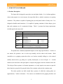
1
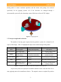
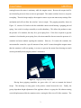
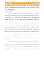
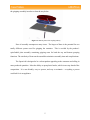
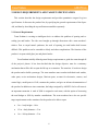
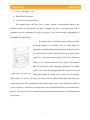
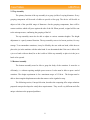
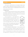
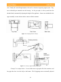
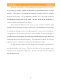
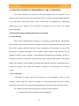
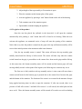
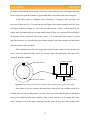
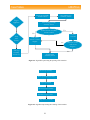
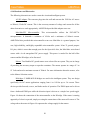
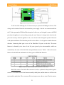
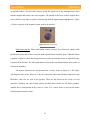
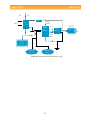
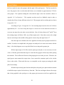
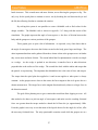
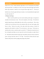
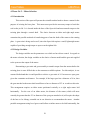
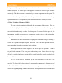
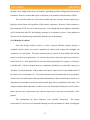
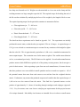
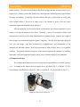
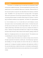
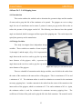
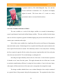
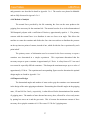
1. EXECUTIVE SUMMARY
1.1 Product Description
The Open-Aid is designed to open glass jars and plastic bottles. It is a kitchen appliance
whose main purpose is to assist anyone, but especially older or arthritic consumers, in opening
containers. The product is capable of opening glass jars and plastic bottles of many sizes. It is
designed to handle round containers. It is capable of opening containers of other shapes, given
that such containers are of a symmetrical design. Table 1.1 presents the design requirements
decided upon for the Open-Aid.
Issue
Budget
Schedule
Appliance
Container
size
Intelligence
Safety
Requirement
$400 + $100 personal funding
14 weeks for total project
Lightweight
user-friendly
easily stored
Height (in.)
2 - 10
Body Diameter (in.)
1.5 - 5
Lid Diameter (in.)
1-5
microprocessor integrating sensors, H-Bridges and motors
protect electronics
safe for user operation (i.e. no sharp edges)
Table 1.1. Design requirements for Open-Aid
The product has a manually adjustable height over the range specified above. It relies on
two motors for operation –one is in the top assembly, and the other in the bottom. Both
assemblies use a gripping system that relies on a bracket assembly sliding in a slot oriented
radially inward with a peg riding in a spirally slotted plate, as seen in Figure 1.1. In both
instances, the motor drives the spiral plate to compress the grippers onto the container and its lid.
The design of these systems is of utmost importance, as it only requires two motors to provide
three functions: grasp the lid, grasp the body of the container, and twist the container open.
The entire product was built around these systems, of which the rotating plates are
approximately 7 inches in diameter. The sensors are embedded in the gripping brackets and
1
turning plates to ensure consistent operation, and the motors and gearing were selected
specifically for the gripping systems. All of the electronics are managed through a
microcontroller, powered by the alternating current of the house with an AC/DC adapter.
Figure 1.1. Gripping System
1.2 Concept strengths and weaknesses
The number of moving parts requires that the product’s systems be evaluated in all
aspects of the design. Table 1.2 highlights the major issues with the design of the product.
Component
Strength
unlimited number of
potential grippers
Spiral
Magnet Sensors
Grippers
Contact Switches
Gears
Height adjustment
Weakness
Carefully selected geometry
Importance
high - the basis of design for the
entire product
only sensors require
power, magnet does not
None
low - there are no wires to tangle,
reducing problems
spring loaded for more
uniform grasping
increases part count, only a fixed
force reaches contact switch
medium - ensures that all grippers
grip with even force
Small
wires can get twisted if not
controlled
medium - wires twist, which must
be accounted for in the design
positive contact/force
transmission
may be loud, small pitch requires
precision
automatically moves up
with lid displacement
requires user to initially adjust it
manually
high - gears transmit the torque to
the container applied by the motors
low – automated system not
necessary; user able to lift top
assembly manually
Table 1.2. Strengths and weaknesses of the main components of the Open-Aid
As previously stated, the spiral plate assemblies minimize motor count and allow for as
many gripping arms as the manufacturer desires. The magnetic sensors are optimal for position
2
sensing because the sensor is stationary while the magnet rotates. Because the magnet itself is
not electrically powered, it has no wires to get tangled. The contact switches, however, are prone
to tangling. Thus the design employs the magnetic sensors to prevent unnecessary turning of the
mechanism and will not allow the switches’ wires to tangle. The gripping assembly, shown in
Figure 1.2, consists of a bracket with the embedded contact switch housing a gripping pad and
spring. One switch is used per assembly to avoid redundancy. This allows the product to sense
the presence of a container, but only for a given spring force. If the force required to grip the
container is less than the preset spring force, the microcontroller does not sense the presence of a
container and must continue opening the container. However, if it senses the container, the
microcontroller counts for a specific amount of time, and if it senses through the magnet sensor
that the container is still not opening, it reverses to prevent the motors from drawing too much
current, potentially destroying the product’s electronics.
Figure 1.2. Gripping assembly components
Driving these gripping assemblies are gears with a 6:1 ratio to transmit the desired
torque. The advantage to using gears is the positive contact between the two. Finally, the
gravity-dependent height adjustment of the appliance allows it to grasp the lid without resisting
vertical displacement while the container twists, causing the lid to rise off of the container. The
3
only disadvantage to this is that the user must manually raise and lower the top portion.
However, it is rationalized that if the user is able to lift the jar or bottle to be opened, he or she is
able to lift the appliance top.
1.3 Design Influences
Designing a kitchen appliance requires the consideration of many factors. The consumer
must see it as a viable and user-friendly product. The manufacturer must be able to market and
sell the product, all at a reasonable price. The following are the key issues addressed in
designing the Open-Aid: user effort, container centering, height adjustment, cleaning, and
simplicity of assembly.
Once plugged into the wall outlet, the user has a minimal amount of effort. The product
rests at its 2 in. minimum height, allowing for easy storage. The user simply raises the upper
portion of the product and with the other hand places the container to be opened roughly in the
center of the appliance. The user then lowers the upper assembly onto the container, resting
there by gravity, and presses the start button. The appliance closes first on the lid to center the
container, then on the body of the container and continues twisting the container open with the
bottom assembly. Once open, the appliance reverses its motors to release the opened container.
The user lifts the upper assembly off of the container and removes the open container with the lid
resting on top.
Cleaning is addressed in the design of the product by essentially enclosing the electronics
and sealing them away from the atmosphere. Both the upper and lower assemblies employ
plastic shields built into the system that also serve the purpose of supporting the subassemblies
used by the product. The upper assembly will not need to be cleaned, as the spillage will drip
down off of the product. The bottom assembly, shown in Figure 1.3 allows the user to remove
4
the gripping assembly in order to clean the tray below.
Figure 1.3. Bottom plates with coupling and tray
Ease of assembly encompasses many issues. The largest of these is the potential for two
totally different systems used for gripping the container. This is avoided by the product’s
spiral/radial plate assembly containing gripping arms for both the top and bottom grasping
functions. The similarity of between the assemblies minimizes assembly time and complications.
The Open-Aid is designed to be a robust product appealing to the consumer and selling in
mass-produced quantities. It has the ability to open plastic bottles, which is one step ahead of the
competition. It is user-friendly, easy to operate, and easy to maintain – everything a person
could ask for in an appliance.
5
2. DESIGN REQUIREMENTS AND TARGET SPECIFICATION
This section describes the design requirements and provides quantitative targets for given
specifications. It discusses the product first, by specifying the general requirements of the OpenAid, and then by describing the top and bottom assemblies separately.
2.1 General Requirements
Team Pratham is creating an intelligent device to address the problem of opening and resealing jars and bottles. The idea was brought up through discussion with a team member’s
relative. Due to carpal tunnel syndrome, the task of opening jars and bottles had become
difficult. This problem can be extended to elderly and other complications. The function of the
product is to open sealed glass jars and plastic bottles.
Team Pratham initially defined general design requirements to guide the team through all
of the project’s phases. It has been decided that the design objective must be a stationary
mechanism that will be able to open the lid/cap on a container. The team has 14 weeks to design
the product and to build a prototype. The team members must conduct individual trade studies,
order parts, revise mechanism designs, fabricate parts, account for electronics, sensors, and
control logic, model parts in CAD, construct the product, and give an in-house demonstration of
the product. In addition to time constraints, the budget assigned by AME470 Ltd. to all teams is
an important constraint. A total of $400 is assigned to each team, with the option of increasing
the total budget to $500 by member contributions. The team members have also set specific
target requirements on the containers for the product to be able to open:
•
2 in. < body height < 10 in.
•
1.5 in. < body diameter < 5 in.
•
1 in. < lid/cap diameter < 5 in.
6
•
0.3 in. < lid height < 1 in.
•
Plastic/Glass Containers
•
Twist-off lids, no pull-off caps
The opening device will have to be “smart” enough to automatically adjust to the
different varieties of body/cap/lid sizes that a container may have. A microprocessor will be
integrated into the mechanism in order to provide it with the necessary programming to
accomplish its required task.
The product (Fig. 2.1) should be kept as light as possible.
Its height should be extendable, and its width should be
adjustable to meet the jar/bottle specifications. It must be able to
be easily cleaned. It will be waterproof (in case of spills), and it
must have a convenient power supply for the user, whether by
battery or AC electricity from the user’s house. The materials
that will be used are rubber, aluminum, and plastic. The rubber
will be very useful for the grips and for the opener’s base, and
Fig 2.1. Initial Concept Design
metal parts should be coated with an anti-corrosive material.
Since safety is a priority, all safety risk issues will be identified and dealt with during the
completion process. The mechanism should not have sharp corners, and it should have enclosed
gears and motor; it should have warning labels where potential hazard may be encountered by
the user. Also, the user will be provided with a user manual with the product’s specifications and
safety issues.
7
2.2 Top Assembly
The primary function of the top assembly is to grasp jar lids of varying diameters. Every
grasping component will be made of rubber to provide a firm grip. The device will be able to
adjust to lids of the specified range of diameters. On the grasping components, there will be
contact switches which will press against the side of the lid. When pressed, a signal will be sent
to the microprocessor, confirming the grasping of the lid.
The top assembly must also be able to adjust to various container heights. The height
adjustment is a purely manual function. The top assembly rests at its lowest position, for easy
storage. To accommodate containers, it may be lifted by the user with one hand, while the user
places the jar in the machine with the other hand. It was determined that if the user is able to lift
a jar or a bottle with one hand, he or she is able to lift the top assembly to place in it the jar or
bottle to be opened.
2.3 Bottom Assembly
The bottom assembly must be able to grasp the body of the container. It must do so
efficiently; i.e. without requiring multiple power sources. It also must be able to open a sealed
container. The design requirement is for a maximum torque of 15 lbf-in. The design must be
able to detect angular displacement so that the motors can be signaled to stop.
The following section, Concept Selection, describes the competing offer unique solutions
proposed concepts developed to satisfy these requirements. They are all very different and offer
unique solutions to the proposed problems.
8
3. CONCEPT SELECTION
This section gives a detailed discussion of several appropriate competing concepts
considered for subsystems, including sketches and schematic representations. It also contains a
table that compares strengths and weaknesses of competing designs that justifies the selection of
the final concept chosen by Team Pratham.
3.1 Competing concepts
The Open-Aid container opener started out with various concepts for its design and those
of its subsystems. Eventually those concepts were either eliminated or refined to be part of the
product outlined elsewhere in this report. The following is a general overview of the proposed
concepts and the decisions made to arrive at the final concept.
The first concept, Figure 3.1, is a square looking device in
which all of the mechanisms are found in the top assembly. A pair of
arms driven by one motor grips the body while a set of grips closes in
on the lid, each grip driven by its own motor. Another motor is used
to turn the entire gripping assembly to open the container. Finally,
another set of motors is used to automatically adjust the height of the
device using a threaded nut riding up and down a threaded shaft. A
Figure 3.1. Concept 1
microcontroller drives all these mechanisms.
The visible grasping arms are proposed in Figure 3.2. They are comprised of a single
motor driving two arms simultaneously. Embedded in the upper portion of the product are a
turning assembly, lid grasping assembly, and vertical height adjustment assembly, all seen in
Figure 3.3. The turning assembly relies on a single motor mated to a rounded gear to spin the
entire grasping assembly. The lid grasper relies on 3 motors, each attached to its own gripping
9
arm. Finally, the vertical height adjuster relies on 2 to 4 motors at opposing support posts. They
turn a threaded gear mounted onto the housing. As the gear spins, it rides up and down the
threaded shaft, automatically adjusting the height of the appliance. Sensors are embedded in the
upper assembly to sense when it makes contact with the container.
Top View
Front View
Side View
Figure 3.2. Grasping arms for concept 1
Grasping assembly
Motor (x3)
Gear teeth
Height
Adjustment
Motor
Turning
Assembly
Threaded
gear
Motor
Figure 3.3. Concept 1 upper housing components
Concept 2 is a unique device. It uses slender arms to grasp the lid of the container, and
has grips that close in on the body at the bottom. The lid gripping arms are manually adjusted
10
for height and the driving motors are encased in the base of the product. The grips that close in
on the bottom of the container’s body, once held in place, are then twisted so that the container is
opened by turning the body, rather than the lid. A rough sketch is shown in Figure 3.4.
Concept 3 is a round machine, enclosing all of the moving parts in its housing in some
manner. In doing so, it takes the safety of the user into utmost consideration. Its shape also
suggests the shape of the containers it is designed to open, as well as being easy on the eyes.
Figure 3.5 depicts a rough sketch of concept 3. The concept uses a base twisting on a threaded
shaft to serve the dual purpose of height adjustment and twisting the container open. The grips
on the top are for the lid and are shielded by the housing, both out of sight and out of reach of the
user.
Figure 3.5. Concept 3
Figure 3.4. Concept 2
Concept 4 is a handheld device with a similar
appearance to the crane arm used in arcade machines to pick up
plush toys. It is held over the container by the user, with the
batteries placed in the handle to distribute the weight of the
appliance. Its crane arms are screw-driven, with some options
of how to do so. The upper gripping portion would contain the
Figure 3.6. Concept 4
11
system found in Concept 1. Figure 3.6 depicts the shape and rough proportions of the concept,
as well as the proposed arm driving mechanisms.
Some other subsystems were offered as well. Subsystem A, shown in Figure 3.7, is a
container grasping mechanism. It is a type of four-bar mechanism driven by a worm gear at one
of the base points. As the worm gear turns, the linkage extends out to the container. Subsystem
B is a grasping mechanism used for the lid. It consists of two plates, one with a spiral groove
and the other with a radial groove for the gripping mechanism to ride in. The entire assembly is
driven by a single motor, as depicted in Figure 3.8. The concept is similar to that of the grips
used to hold a drill bit in place.
Driven pin
Figure 3.7. Subsystem A: 4-bar grasping mechanism
Figure 3-8. Subsystem B
Given such a diverse offering of concepts and subsystems, the systems proposed in each
were compared based on their strengths and weaknesses. Table 3.1 is a complete listing of such
characteristics. It shows the different features for the 4 different concepts and 2 subsystems. This
table was used to compare and ultimately arrive at a final concept agreed upon by the group,
discussed next.
12
Concept
Features
Strengths
Weaknesses
all components in upper
assembly
all torque transmission occurs on the
housing
1 motor for container grippers
minimizes motor count for system
3 motors for gripping lid
good force application
more motors means more
weight
1 motor for twisting lid
minimizes motor count for system
requires high torque and parts
fabrication
2-4 motors for height
adjustment
automatically operates for the user
adds weight, requires threaded
gear
all electronics in lower
assembly
bottom-heavy
requires spill protection
slender arms for gripping the
lid
aesthetically pleasing
height adjustment, force
transmission
bottom twists container open
requires less torque than the lid
round design
aesthetically pleasing
all components shielded from
view
safety, clean appearance
bottom raises and twists
container
integrates two functions into one
handheld device
unique concept
crane-like arms
aesthetically pleasing
Subsystem
A
4-bar linkage for gripping
efficient force transmission
difficult to package, expensive
worm gears, 2 motors (1 per
linkage)
Subsystem
B
Spiral/radial grippers
minimizes motor count, allows for
multiple grips
requires fabrication, powerful
motor
1
2
3
4
top-heavy, crowded assembly
difficult to clean, if necessary
Impractical considerations of
mechanics, parts interference
may be too heavy for
consumers, difficult to center on
container
insufficient torque transmission,
no height adjustment
Table 3.1. Strengths and weaknesses of the concepts and their features
3.2 Final Concept
The final concept chosen for further study is a combination of many of the above
systems. It essentially incorporates the systems from Table 3.1 that had the greatest advantages
and the least disadvantages. Thus, the final concept was determined based on considerations for
the consumer, manufacturing, and effectiveness of the product.
13
The chosen concept hinges on the spiral/radial plate assembly of subsystem B. It allows
for one motor per assembly, regardless of the number of grips deemed necessary for proper
operation. It also allows for the gripping and twisting of the container simply by continuing
turning the driving motor. The top and bottom assemblies rely on this design, the bottom
incorporating the twisting aspect of the product. The final concept has the round shape of
concept 3, although is fundamentally very different.
Other concepts had influences on the design, as well. Concept 1’s automatic height
adjustment system, although a nice feature, is unnecessary. The disadvantages are large enough
to outweigh the advantages in terms of weight savings, part count, and cost of manufacture.
Concept 2 has all of the electronics mounted to the bottom assembly. The final concept splits its
electronics between top and bottom, but with the microcontroller and power source in the lower
assembly in order to lower the center of gravity. The slender arms of concept 2 do not easily
transmit a large force to the lid of the container, thus eliminating such a design.
The pages that follow address this final concept and its development. They describe its
operation and interface with the user. They also detail three of the more important issues
associated with the development of this product. Thus, the reader may now turn the page and
delve into the Open-Aid.
14
4. CONCEPT TECHINCAL DESCRIPTION AND VALIDATION
This section discusses the operation of the system/product and user interface. It also
discusses three technical design issues/components that are central to the operation/performance
of the Open-Aid: spiral plate design, motor selection and lid gripping arms. Engineering
justifications for the design of the Open-Aid are detailed for each of these key design
issues/components.
4.1 Operation of the system/product and user interface
4.1.1 Introduction
This section is divided in three main parts: user interface, product logistics, and hardware
and electronics. First, the user interface is explained. This brief explanation shows the interaction
between the customer and the Open-Aid. Then, the logistics of the product are given. This
incorporates a detailed description of the different actions required and performed by our
appliance in order to open a container. It also addresses off-design issues and safety concerns. It
also shows the mode in which the system functions and is operated with means of flow charts.
Finally, the hardware section explains and details the different electronic components that are
used in the product. This section also includes a complete circuit drawing of the electrical
system.
4.1.2 User Interface
It only takes six simple steps for the customer to use the appliance. The rest of the
necessary actions required to open the container are done automatically after the customer
presses the ‘start’ button. The operation and automation are discussed in the following section.
The customer will take the following steps in order to use the appliance:
1. Connect Open-Aid to wall outlet (Turn on appliance)
15
2. Adjust height of the top assembly to fit container to open
3. Place the container on the bottom plate of the opener
4. Activate appliance by pressing a ‘start’ button found on the side of the housing
5. Take container out of the container opener
6. Open another container/unplug the appliance
4.1.3 Logistics of the product
Once the user has placed the jar/bottle in the Open-Aid, it will open the container
automatically after pushing a ‘start’ button that will be found in its housing. When the user
activates the appliance, an automated series of steps will start the opening of the container.
Notice that every time the product is turned on, the grips at the top and bottom assembly will be
reset to their initial position at the maximum radial outer diameter.
First, the top assembly motor is started. This action will move the top assembly grips
radially inward until the lid/cap is held secured. The motor will then stop when the contact
switch located on the grip is pressed due to the contact force between the grips and the lid/cap.
At this same time, the bottom assembly motor will be started and the bottom grips will start
moving radially inward. At this point of the logistics, the following two scenarios may occur.
The first case is fairly similar to the top assembly action. A time count will start when a
contact switch located at the bottom grip is pressed due to the contact force between the grips
and the bottom of the container. The function of the count is to account for the amount of torque
being applied (twisting time) in order to open the container. If, after one second, there is no
presence of hall effect sensor 2 and hall effect sensor 1 is still sensed, the radial plate did not
move at all. Thus, the bottom assembly motor will be turned off in order to avoid overloading
16
the motor and potentially destroying the electronics. This off-design issue will happen when the
torque required to open the container is greater than that for which the Open-Aid is designed.
A hall effect sensor is a magnetic sensor consisting of 2 magnets, and our product will
have two of them on (Fig. 4.1) located on the radial plate of the bottom assembly and 180° from
each other. As shown in Figure 4.1, one of the hall effect sensors, sensor 1, will be placed so it is
sensed when the bottom grips are moving radially inward. Then, our program will be looking for
the presence of the second hall effect sensor, sensor 2. If it senses hall effect sensor 2 (second
hall effect sensor is on), the radial plate has rotated enough to open the container and the bottom
assembly motor will be turned off.
If the container opens due to the torque generated before the contact switch is pressed, the
motor will be on until hall effect sensor 2 is sensed. Again, the radial plate will rotate 180°,
enough to open the container.
Hall effect sensor 1
Container to open
Housing
Hall effect sensor 2
Radial plate
bottom assembly
Figure 4.1. Representation of the hall effect sensors to help comprehend the logistics of the product
After either of the two scenarios discussed above takes place, the container needs to be
released. First, the top assembly motor is reversed. This motor turns until the grips are positioned
back to the maximum radial outer diameter. This is done with the use of another hall effect
sensor, located at one of the grips on the top assembly. Once the grip gets close enough to the
17
magnet located in the housing (maximum radial outer diameter), the magnet sends a signal to
stop the motor.
The same function occurs at the bottom assembly. Once the top assembly motor is turned
finished, the bottom assembly motor reverses and stops until hall effect sensor 1 is detected
again. This will bring the bottom grips back to their initial position (maximum radial outer
diameter).
Another off-design issue is if the lid/cap of the container is too small for the appliance.
There are certain specifications for the sizes of bottles the product can open. Notice, however,
that when the Open-Aid tries to open a smaller bottle out of specification, the switch is never
pressed as there is not a contact force anymore. To solve this problem, a hall effect sensor,
placed at the minimum radial inner diameter for the grips in order to specify when the grips are
closest to each other. Then, when the hall effect sensor is sensed, the top assembly motor is
turned off.
There are no major safety concerns with the product. All the electronics are covered by
the housing. Also, there are no dangerous or harmless external gaps between components. The
only safety concerns will occur when adjusting the height of the top assembly. A warning sign
will be placed on the housing that warns about pinching one’s hands.
Figures 4.2 and 4.3 show the algorithms that represent the action of opening and releasing
the container, respectively.
18
Sense top assembly
contact switch
Plug in
appliance
Start turning bottom
assembly motor
Sense bottom assembly
contact switch?
No
Press
‘start’
button
Turn top
assembly
motor on
Stop turning top
assembly motor
Yes
Count to
1 second
Hall effect
sensor 2 senses
magnet
No
Hall effect sensor
1 still senses
magnet?
Yes
Stop bottom
assembly motor
Figure 4.2. Algorithm representing the opening of the container
Reverse top assembly
Sense top assembly hall effect
Stop top assembly
Reverse bottom assembly
Hall effect sensor 1 senses
Stop bottom assembly
Figure 4.3. Algorithm representing the releasing of the container
19
4.1.4 Hardware and Electronics
The following electronics are used to create the circuit and intelligent system:
AC-DC adapter: The converter plugs into the wall and converts the 120Volts AC source
to 500mA, 6Volts DC current. This is the necessary amount of voltage and current for all the
other electronics to work appropriately. AME470Ltd provided this adapter at no cost.
Mini-Max/PIC
Microcontroller: This microcontroller utilizes the PIC16F877A
microprocessor. It demands a minimum of 6Volts and a minimum of 100mA current.
AME470Ltd also provided this microcontroller at no cost. Mini-Max is a general purpose, low
cost, high reliability, and highly expandable microcontroller system. It has 33 general purpose
I/O pins, which is more than enough ports for the Open-Aid. Also, the Mini-Max series board
comes with a 6-volt unregulated DC power supply. This power is needed for the hall effect
sensors and the H-bridges, to be discussed.
Motors: Two Buehler DC geared motors were selected for our system. They are in charge
of providing the necessary torque to open the containers. The motors operate in a range of 3 to
12 Volts and need a maximum current of 200mA. For more information about the motors, refer
to the Motors Selection section.
H-Bridges: 2 NMIH-0030 H-bridges are used in the intelligent system. They are design
specifically for DC motor applications ranging from 6 to 18Volts up to 5A current. These
devices provide forward, reverse, and brake modes of operation. The PWM input can be driven
from a dedicated PWM port while the direction input is driven as a simple low speed toggle.
Figure 4.4 shows the connection of the microcontroller to the H-bridge. If the motor is turning
oppositely of what is expected, simply reversing the connections of the motor will correct it. The
voltage above the motor in Figure 4.4 represents the voltage supply for the motors.
20
Figure 4.4. H-bridge connection to the motor and microcontroller
To the left of the H-bridge, the 5 Volts necessary to operate the H-Bridge are shown. This
voltage can be obtained from the microcontroller power supply. Also the two connections below
the 5 Volts represent the PWM and Direction pins. In this case, an On signal is sent to the PWM
pin when the appliance is activated (by pressing the ‘start’ button). A change in the value for this
pin is not necessary when the appliance is on, as we do not need to change the speed of the motor
or the pulse modulation. The Direction pin will receive either a 1 or 0 signal to control the motor
direction. Connecting both pins to two of the Mini-Max I/O ports can do this. The motor
behavior is dictated by the value of the I/O ports given by the microcontroller, which are
controlled by the status of the hall effect and push-button sensors. Table 4.1 shows the motor
behavior for the different combination of values given to PWM and Direction
Table 4.1. Function Table that characterizes the behavior of the motor.
Hall effect sensors: Four hall effect sensors are used, as explained in the product logistics
section. Two of them will be in the bottom assembly radial plate, and the other two will be in the
top assembly spiral plate. These sensors tell the microprocessor when to turn off/on the motors,
21
as explained above. The hall effect sensors switch the signal sent to the microprocessor when
both the magnet and sensor come close together. The normal of the faces of these magnets have
to be parallel to each other in order to function and send the signal change appropriately. Figure
4.5 shows a picture of the magnetic sensor used in our product.
Figure 4.5. Hall effect sensor
Push button sensors: Three push button sensors are used. Two of them are simple small
push button sensors that will be located in both top and bottom assembly grips. When the button
is pushed, a signal is sent to the microprocessors to start a determined action, as explained in the
Logistics of the Product. The other push button sensor is the start button that the user pushes to
activate the appliance.
All of these electronics are incorporated into a circuit, shown in Figure 4.6. The OpenAid integrates this circuit. However, it has an extra motor and extra H-bridge connected to the
Mini-Max, since two are used in the product. These are not shown in the circuit to avoid
messiness. Similarly, the push button sensors and hall effect sensors are all shown together.
Another device incorporated in the circuit is a fuse. It is a safety device to prevent the motor
from drawing too much current.
22
HV
LV
Fuse
120V
6-12V
100m
AC-DC
Converter
MiniMax
5V
3-12V
H
Bridge
I/O
pins
Start
Button
Push button
sensors
Hall effect
sensors
Figure 4.6. Representation of the electronics circuit
23
Motor
4.2 Issue No.1 – Spiral Plate Design
4.2.1 Introduction
The first key technical design issue is the functionality of the bottom assembly of the
Open-Aid. This section will describe the scientific method used to design the spiral plate. This
assembly must grasp the body of the bottle/jar container and rotate it until the seal of the lid has
been broken. In order to achieve this, a two plate system was conceived. The top plate contains
radial grooves that allow the grasping devices to slide in and out. The bottom plate has spiral
grooves that push the graspers into the body of the container. The basic set up of this device is
shown in Appendix 5.4.2. This analysis determined the best way for these parts to interact,
focusing on the transmission angle between the spiral groove and radial groove.
4.2.2 Design Variables
The design variable is the parameter that is directly engineered into the Open-Aid. For
this technical issue, the only design variable is the shape of the spiral and radial grooves on the
two plates. This variable had an infinite number of design options. The effects of different
constant angles of convergence and different variable angles of convergence were compared.
The major constraint on the design variable, the grooves, was the ability to hold bodies with a
minimum 1.5 in. diameter and a maximum of 5 in. diameter. This gave the constraint of a
minimum 3.5 in. of movement on the radial grooves due to the difference in radii of the specified
containers.
4.2.3 State Variables & Measures of Merit
There were many state variables directly affecting the performance of the Open-Aid that
resulted from this one design variable. The first of these state variables was the speed at which
the grasping device moves up the radial groove. Based on this, a second state variable was the
24
torque that must be withstood by the radial plate to prevent it from rotating before the body is
securely grasped. The next state variable was the ratio of the torque applied by the spiral plate
and the frictional force between the graspers and the body of the jar of bottle. This state variable
was the one that confirmed that there was enough friction to twist the lid without slipping. The
final state variable was the cost that it will take to create and assemble this unit into one piece.
There were three measures of merit used to determine the best solution for this design
variable. The first was the amount of torque needed to be applied to the radial plate in order to
resist plate rotation while the graspers are moving toward the body. This is important because it
is the delay of the radial plate’s rotating until the body is grasped that allows the Open-Aid to
sense that it has begun removing the top. The second measure of merit was making sure that
enough force was being applied to the body by the graspers. This force ensures that there is
enough frictional force to prevent slipping when the radial plate turns.
This is the most
important measure of merit because it affects the primary function of the tool. If the spiral shape
does not create enough friction, the Open-Aid opener will be unable to open the jar/bottle. A
third measure of merit was the cost of producing the parts. If a smaller angle on the spiral plate
creates the best result, we still cannot just create the smallest angle piece possible. It is also
important to remember the cost of the smaller angles. The smaller the angle, the longer it takes
for the slot to cover the necessary 3.5 in. This creates longer and more difficult work that should
try to be avoided.
4.2.4 Method of Analysis
The method used to solve this problem was based on static mechanics. There were two
states in which static mechanics were looked at. The first was while the grasping devices were
sliding up the radial groove. The force that is needed to keep the radial disc in place depends on
25
the force needed to move the graspers and the angle of the spiral groove. The force needed to
move the graspers, due to acceleration and friction, was calculated at approximately 0.25 lbf for
each grasper. The equation relating this value and the angle to the force needed is shown in
Appendix 5.4.2 as Equation 1. This equation was then used in a Matlab® script in order to
simulate the effects of many different values for θ. This program and its resulting plot are shown
in Appendix 5.4.2.
According to Figure 3 in Appendix 5.4.2, the resisting torque must be close to 0.2 ft-lbs at
approximately 45o. It is best to keep the torque at a lower level so the motor does not have to
overcome too many forces in order to twist the body. Since all values between 10o and 45o keep
the resisting torque well below 1ft-lb., any of these angles work. Since there seems to be a slight
increase in the slope in the middle of the graph it is best to keep the angle below 35o.
Once the angle was calculated, the force applied to the body by the graspers needed to be
studied. In order to accomplish this, the grasper was analyzed as it comes into contact with the
body. A free body diagram was set up with all the forces acting on the grasper pin.
With an input torque of 14 ft-lbs onto the spiral grooved plate, it was necessary to create
a force of friction greater than that torque to ensure that the grippers will not slip while opening
the container. The coefficient of friction of the grasping devices on the jar is one. Therefore, the
spiral groove must transmit the torque into a force toward the container equal to the circular
force at that radius. What made this easy to accomplish was the torque preventing the radial
plate from rotating.
With the torque already placed on the radial plate, the spiral grove plate needed a moment
to build the torque required to break away from that. This does not happen because the torque
that is being applied by the spiral grove to the grasper pin increases as the force applied to the
26
bottle increases. This created more and more friction, never allowing the graspers to slip. The
only way for the spiral plate to continue to move was by breaking the seal between the jar and
the lid, thus allowing freedom to continue the rotation.
By solving this system it was possible to create a Matlab® code to find values for the
design variables. The Matlab® code is shown in Appendix 5.4.2 along with the results of the
simulation. The graphs represent the angle of convergence vs. the force of friction between the
body and the graspers at various positions of the graspers.
These graphs gave us quite a bit of information. As expected, every chart shows that as
the angle of convergence decreases the friction created on the body grows larger and larger. The
other important data that can be gathered from these charts is that as the graspers move in further
they create more and more friction. The reason behind the first phenomenon is an idea as simple
as a wedge. As the wedge is pushed in one direction, it transfers force in other directions
perpendicular to the surfaces of the wedge. The second fact deals with the radius and torque that
the particle is experiencing. The important idea behind this fact is the ratio of force and torques.
The torque that the spiral plate has applied to it and in turn applies to other parts is always
constant. As the graspers move closer to the center, the force tangent to the circle grows due to a
shorter moment arm. This larger force in the tangent direction directly relates to a larger force in
the direction normal.
The goal of this planning was to get a rotation that would not allow slipping to occur. All
that needed to be done was pick an angle of convergence and make sure the resulting frictional
force was greater than the torque needed to detach the lid form the jar, approximately 14lbs.
From the graphs it was easy to see that most of the logical choices for the angle do, in fact, offer
the necessary frictional force. The only questionable scenarios result while the graspers are at a
27
radius of 6 in. or 4.8 in. In these situations, angles that are over 35o could present some problems
and not open all lids. It would be nice to have a bit of space between the angle chosen and the
failure angle; therefore it would be wise to keep the chosen angle under 35o. This may be
familiar because from the graph with the pin in motion, it was determined that the angle should
try and be kept under 35o.
4.2.5 Impact on Design
While it would be possible to try and create the smallest possible angle, it is important to
remember the third measure of merit. That was the simplicity of the design. The smaller the
angle the longer the groove and the harder the work it will be to create this piece. That is why it
would be best to try and keep in closer to the maximum while at the same time keeping a high
factor of safety.
Based on the results of the study and the three measures of merits, the
appropriate choice should be less than 35o but at the same in a close range. The decision was
made that the best choice to make the spiral cut would be 30o. Without this research the idea of
how to design this spiral shape was just a vague idea, but after it the numbers are right in front of
me. The numbers attained from this engineering work definitely justify the decision to make the
groove converge toward the center at a 30o angle. This decision will then affect the major
function of the product, which is grasping and opening of the jar/bottle.
28
4.3 Issue No.2 – Motor Selection
4.3.1 Introduction
This section of the report will present the scientific method used to choose a motor for the
purpose of twisting the base plate. This motor must provide the necessary torque to break the
seal on the jar lid. It is located inside the base of the Open-Aid and must transfer torque to the
twisting plate through a central shaft. The choice between an inline and right angle motor
constrains the possible methods of transferring power from the shaft of the motor to the rotating
plate. A gear train is being used as well, since the Open-Aid requires a small, lightweight motor
capable of providing enough torque to open even the tightest lids.
4.3.2 Design Variables
The design variables are the parameters over which we have direct control. In regards to
the motor selection, the design variables are the choice of motor model and the gear ratio applied
to the system at the output of the motor.
Determining a gear ratio and gear assembly to transfer torque from the motor shaft to the
twisting plate is more difficult due to the numerous available options. For this analysis, it was
assumed beforehand that it would possible to achieve a gear ratio of 6:1 between two spur gears
given the constraints on diameter. For example, if the larger gear has a diameter of 4 in., then
the gear attached to the motor shaft would have to have a diameter of 2/3 in. to achieve this ratio.
This arrangement requires an inline motor positioned vertically or a right angle motor laid
horizontally. For the case of an inline motor, the diameter of the motor (which will most
certainly be greater than the 2/3 in. diameter of the spur gear attached to it) will require the shape
of the base to be oblong, extended out in one direction to accommodate the motor. Another
possible arrangement using bevel gears would allow an inline motor to be laid horizontally, but
29
bevel gears usually are produced in pairs at a 4:1 ratio and are much more expensive than
standard spur gears. The limited space of the appliance constrains the choice of gear assemblies
considerably. The choice of motor is constrained by the torque requirement for the system. The
motor must be able to provide 1,400 oz-in of torque. This value was determined through
experimentation and will be explained in greater detail in the Methods of Analysis section.
4.3.3 State Variables & Measures of Merit
The state variables quantitatively describe the performance of the system. They are
determined entirely by the choice of design variables. It is important to formulate a group of
state variables that adequately describes all of the aspects of a product. For the Open-Aid, the
important state variables are output power, output torque, angular velocity of the twisting plate,
weight of the motor, size of the motor, and cost of the motor.
While there is no direct constraint on the output power of the motor and gear assembly, it
must be able to produce an output torque of 1,400 oz-in. This is the most important constraint,
since a motor that is incapable of opening a jar is worthless.
Initial requirements set a target weight of 8 lbs. for the Open-Aid appliance. In light of
this goal, a hard constraint of 5 lbs. was placed on the primary motor. Motors above this weight
will not be considered and motors nearing the five pound limit will be heavily penalized in the
Measure of Merit.
The size of the motor is constrained by the size requirements for the base of the
assembly. The Open-Aid has been designed to accommodate containers with diameters up to 5
in. The width of the base is larger than this, so the motor is given a constraint of 6 in. on the
diameter (or length, depending upon the configuration). No requirement was set for the height of
30
the base, so the length of the motor (or diameter, depending upon the configuration) has no hard
constraint. However, motors that require a taller base were penalized in the Measure of Merit.
The cost of the motor is a crucial state variable since the customer will not want to pay a
high price for the Open-Aid, regardless of the features it possesses. Because of this restriction, a
hard constraint of $50 was set for the motor price. Even though this entire appliance should not
sell for much more than $50, developing a prototype is an expensive process. Mass production
cuts the cost of manufacturing considerably from the cost of prototyping.
4.3.4 Methods of Analysis
Since this design analysis involves a choice between different product designs, a
weighted decision matrix was used to quantitatively analyze and compare the strengths and
weaknesses of each option. The final selection process focused on four models that did not
grossly exceed the set requirements. To select the best motor, each motor option was rated on a
scale from 0 to 10. If an option failed to meet the initial requirement for a category, it received a
0 for that mark. Likewise, designs that were completely satisfactory in a particular category (in
which the overall performance of the product could not be improved with extra enhancement of
the feature) were scored with a 10. For features that met initial constraints but were not optimal,
a linear scale was made between the maximum and minimum values for that feature from 0 to 10
and points were awarded to each motor option based upon where it performed on this scale. For
categories without hard constraints, a relative score was determined in-between 0 and 10 when a
motor met the basic requirements, but could be improved to raise the overall quality of the
product.
The requirements for these categories were carefully constructed.
The torque
requirement of 1,400 oz-in was determined through several experiments in which a Quickgrip®
31
bar clamp was fastened to a lid. Weights were then attached to a lever arm on the clamp until the
resulting moment was large enough to open the lid. The required torque for breaking the seal of
the lid was then calculated by multiplying the force of the weights by the length of the lever arm.
The required opening torque for the particular containers is summarized below:
•
Glass applesauce jar – T = 460 oz-in
•
Glass salsa jar lid – T = 1,013 oz-in
•
Plastic Powerade bottle – T = 273 oz-in
•
Glass Snapple bottle – T = 422 oz-in
The data from these experiments can be found in Appendix 5.4.3. The experiment was initially
performed in metric units, so that the salsa jar required 6.5 lbf-in. of torque. A required torque of
15 lbf-in. was selected as a maximum torque to account for any containers which might be tighter
than the salsa lid. This is approximately equivalent to 1,400 oz-in, a standard measurement for
motor output torques. The constraints were for the motor weight at 5 lbs. and the motor diameter
at 6 in., as mentioned previously. The $50 limit was also applied. Several online manufacturers
produce motors which fulfill the required role of the primary twisting motors, but do not give a
price for their motors. After requesting a quote from one such manufacturer, it became obvious
that these products were not available in small quantities and were much too expensive. All of
the potential motors that came from such sources were stricken from the weighted decision
matrix. Furthermore, any motors that produced torques much smaller than the required torque of
1,400 oz-in were also removed from the matrix. This final list of potential motors was the
product of approximately 8 ½ hours of searching through catalogues and webpages (Appendix
5.4.3). Very few motors came even close to satisfying our requirements for this project because
of its unique demands. Most hobby sized motors are intended for use in robots or small remote
32
control vehicles. The Open-Aid will subject this motor to large amounts of torque relative to its
required size. Finding a motor that would fit in a small appliance and still produce large amounts
of torque was difficult. Eventually it became obvious that only a geared motor or rotary plate
motor would produce 1,400 oz-in of torque with a low amount of power, given the space
constraints imposed on both the motors and gears.
After assigning the scores based on these considerations, the relative importance of each
category was rated in relation to the others. Normally, a survey of customers, retailers, and
manufacturers would be used to help determine these weighting factors. Instead, the weight of
each category was determined based the group’s judgment. The two most important categories
were cost and torque, since they determine the competitiveness and functionality of the
automatic jar and bottle opener. If the Open-Aid lags in either of these areas, it is essentially
worthless. The weight, diameter, and power of the motor comprised the categories of middling
importance, while the length and angular velocity were considered relatively less important.
4.3.5 Impact on Design
The weighted decision matrix used to evaluate this design problem is located in Appendix
5.4.3. According to the matrix, the best option was to use motor No. 2, a Buehler 12V DC
Geared Motor from Electronic Surplus Inc, and a 6:1 gear ratio. It is pictured below (Fig. 4.7).
Figure 4.7. Motors used in Open-Aid.
33
The decision to use the Buehler motor was made based on the dimensionless number
scale used in the weighted decision matrix. This motor outperformed all of the others by a large
margin because it was never penalized for failing to meet a requirement. When geared down six
times, this motor produces a torque that is more than sufficient for the automatic jar and bottle
opener. The addition of a 6:1 gear train proved to be a key design variable. This component
allows the DC geared motor to meet the torque requirements for this project. While the Globe
rotary table geared motor produces an enormous amount of torque for its small size, it is still too
large to fit within the constraints set in our requirements. It exceeds the 5 lb. weight requirement
by 1 ½ lbs. Its diameter is over 5 ½ in. It is also a little over 5 in. tall. Furthermore, it was the
most expensive motor to survive the preliminary rounds of selection. All of these factors made
the Globe motor an inferior option to the much cheaper Buehler motor. The small size and
standard cylindrical shape of the Buehler motor do not pose any constraints on the diameter of
the base. Furthermore, the output shaft on the Buehler motor is slightly off center, diminishing
the effective radius of the motor’s body in relation to the base diameter, permitting a smaller and
lighter base. Its length requires the base to be at least three inches tall. This constraint was not
very demanding and was easily met in the design of the appliance’s base.
Parametric analysis of this technical issue succeeded in selecting a motor well suited to
the unique requirements of the automatic jar and lid opener. Due the high torque requirements
and demanding size and weight constraints, the selection of this motor was a difficult and
important task. By setting precise quantitative requirements on the important state variables of
the system and implementing a weighted decision matrix to sort through the remaining potential
motors, this study methodically reduced numerous motor options down to the one most qualified
selection.
34
4.4 Issue No.3 – Lid Gripping Arms
4.4.1 Introduction
This section outlines the method used to determine the geometric shape and the number
of arms used to grasp the lids of the containers to be opened. The grippers are cut to a sharp
angle for ease of manufacture and to ensure 2 points of contact per grip on the lid in order to
reduce the pressure of the gripper on the lid. The following text discusses how that optimal
angle was obtained, both for an upper and lower part of the gripping arm. The results impact the
spiral plate geometry and its manufacture.
4.4.2 Design Variables
This study investigates three independent design
variables. These variables are number of arms required,
Inner Diameter, θ
N, the angle θ, and the angle γ (Fig. 4.8). θ represents the
Outer Diameter, γ
angle between the two faces used to grip the cap on the
inner diameter of the grippers, while γ represents the
angle between the two faces used to grip the cap on the
Figure 4.8. Gripping arm with indicated angles
outer diameter of the grippers.
There are a handful of constraints on the design variables, one of which is the radius from
the center of the container to the outer surface of the grippers. This is a maximum of 2.5 in. and
a minimum of 1.5. The minimum radius is used for evaluation to account for the maximum
necessary gripping force. Another constraint is the radius from the center of the container to the
inner surface of the grippers, which is a maximum of 1.75 in. and a minimum of 0.5 in. Again,
the minimum radius is used for evaluation for maximum necessary gripping force.
The
coefficient of friction of the pads used to grip the lid is the final constraint. The material used is
35
a polymer made by 3M called Bumpon® (Fig. 4.9), and the
friction coefficient is estimated to be 1 for plastics and slightly
higher for metals. This lower value of 1 is used as a safety
precaution in order to account for both surfaces.
Figure 4.9. Bumpon® grips
4.4.3 State Variables & Measures of Merit
The state variables as a result of the design variables are essential in determining a
system’s performance based on the defined design variables. The state variables for this design
issue are: the force required to grip the lid without slipping, the pressure on the lid at the point of
contact, space constraints, and weight.
Each of these state variables has a significant effect on the overall layout of the gripping
arms and related systems. Minimizing the force required to hold the pads in place minimizes the
force required for the motor to sustain. This ultimately results in a less costly motor. Reducing
the force required to grip the lid also reduces the pressure experienced by the lid at each point
where the arms meet the lid. This avoids denting or crushing the lid.
Increasing the angle ultimately reduces the size of the arms. It also becomes a question
of whether or not 3 arms fit in this system. The angles determine the size of the arms. In order
to maximize manufacturing efficiency by using the fewest number of cuts in the arms, larger,
wider angles will decrease the size of the arms used, consequently decreasing their weight.
The design variables detailed above were evaluated through a force analysis conducted
on a general form of the geometric design for the grasping arms. The equations for these forces
36
and geometries are described in detail in Appendix 5.4.4. The results were plotted in Matlab®
and are fully discussed in Appendix 5.4.4.
4.4.4 Method of Analysis
The normal force provided by the lid contacting the faces on the arms produces the
gripping force necessary for the container lids. The material used to do so is the aforementioned
3M Bumpon® polymer with a coefficient of friction µ approximately equal to 1. The primary
concern with the normal force is to distribute it onto two faces at an angle. This allows the
machine to center the container and divides the force into two surfaces to distribute the pressure
on the cap into two points of contact, instead of one, which divides the force experienced by each
point in half.
The primary source of information used to account for the force necessary to open a
container was determined in a simple experiment.
This experiment determined that the
necessary torque to open a container is approximately 6.5 lbf-in. A safety factor of 2.3 was used
to account for especially difficult containers. This bumps the maximum torque up to a value of
approximately 15 lbf-in. The equations and corresponding figures used to determine the optimal
design angles are found in Appendix 5.4.4.
4.4.5 Impact on Design
The determined angles and number of arms used to grip the container were instrumental
in the design of the entire gripping mechanism. Determining the allowable angles in the gripping
arms, 150 and 160 for θ and γ, respectively, is what allowed for the determination of the number
of gripping arms. The number of arms deemed necessary, three, allowed for a less costly motor
by putting less stress on it and the gear train. This is because the maximum amount of force
necessary for to grip the container is 10.3 lbf versus 15.5 lbf for 2 gripping arms.
37