1
Manual
Version V1.0
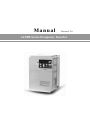
AC80B Series Frequency Inverter
Contents
Chapter 1 Overview……………………………………………………………………………………... 1
1.1 Safety requirement and cautions……………………………………………………………... 1
1.2 Technical criterion ……………………………………………………………………………… 4
Chapter 2 Before Use………………………………………………………………………………….. 7
2.1 Purchase inspection………………………………………………………………………….. 7
2.2 Nameplate ……………………………………………………………………………………... 7
2.3 Standard models and rated parameters…………………………………………………… 8
Chapter 3 Installation and Wiring……………………………………………………………………. 9
3.1 Safety Precautions………………………………………………………………………….9
3.2 Treatment for inverter after longtime store …………………………………………………10
3.3 Inverter stable running environment………………………………………………………...10
3.4 EMI Protection………………………………………………………………………………... 11
3.5 Machinery installation………………………………………………………………………….14
3.6 Electric installation…………………………………………………………………………….21
Chapter 4 Basic Operation and Trial Run…………………………………………………………..35
4.1 Safety Precautions…………………………………………………………………….……35
4.2 Keyboard layout and functions specification………………………………………………..36
4.3 Basic operation…………………………………………………………………………………38
4.4 Trial run………………………………………………………………………………………...42
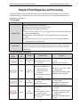
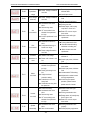
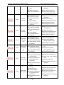
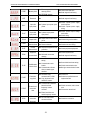
Chapter 5 Fault Diagnoses and Processing………………………………………………………..47
5.1 Fault types……………………………………………………………………………………. 47
5.2 Fault information and details ……………………………………………………………... 47
5.3 Fault diagnoses process ……………………………………………………………………51
Chapter 6 Periodic Overhaul and Maintenance…………………………………………………….57
6.1 Safety Precautions…………………………………………………………………………57
6.2 Overhaul……………………………………………………………………………………….57
6.3 Maintenance………………………………………………………………………………...59
Chapter 7 Peripheral Equipments and Options………………………………………………. 62
7.1 Safety Precautions………………………………………………………………………... 62
7.2 Peripheral equipments……………………………………………………………………... 62
7.3 The use of peripheral equipments ………………………………………………………….64
Chapter 8 Quality Guarantee……………………………………………………………………….. 67
8.1 Guarantee time and range…………………………………………………………………..67
8.2 Liability exemption …………………………………………………………………………...67
8.3 Product application …………………………………………………………………………...67
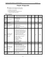
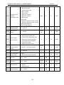
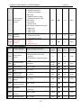
Chapter 9 Function Parameter Specification............................................................................. 68
9.1 Basic parameters ............................................................................................................... 68
9.2 Operation control parameter .............................................................................................. 76
9.3 Switch quantity terminal parameters .................................................................................. 81
9.4 Analog terminal parameters ............................................................................................... 91
9.5 Keyboard and display parameters ..................................................................................... 95
9.6 Motor parameters............................................................................................................... 98
9.7 VC control parameter ....................................................................................................... 100
9.8 V/F control parameters .................................................................................................... 101
9.9 Malfunction and protection parameters ........................................................................... 105
9.10 Machine malfunction code table .................................................................................... 111
9.11 PID parameters .............................................................................................................. 113
9.12 Multi-step, PLC function and swing frequency parameters ........................................... 118
9.13 Communication control function parameters ................................................................. 123
Chapter 10 Appendix.................................................................................................................. 125
10.1 Appendix 1: Function parameter table ........................................................................... 125
10.2 Appendix 2: RS485 communication protocol ................................................................. 152
10.3 Appendix 3: PG card manual ......................................................................................... 159
AC80B HIGH-PERFORMANCE VC INVERTER MANUAL
OVERVIEW
Chapter 1 Overview
Thanks for using AC80 high-performance VC frequency inverter. This manual tells you how to use it perfectly. Please
read this manual carefully and fully understand the safety requirement and cautions before use (installation, wiring,
operation, maintain, checking, and etc...).
1.1 Safety requirement and cautions
Pls do totally understand this part before using the inverter.
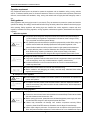
Warning signs and meanings
This manual has used belowing signs that mean there is an important part of security. While observing against the rules,
there is danger of injury even death or machine system damage.
Danger: Wrong operation may cause death or large accident.
Warning: Wrong operation may cause death or large accident.
Caution: Wrong operation may cause minor wound.
Important: Wrong operation may cause the inverter and other machine system damage
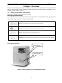
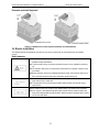
Warning signs position
Warning position 1
Warning position 2
Drawing 1:Warning positions on crust of AC80B series inverter
1
AC80B HIGH-PERFORMANCE VC INVERTER MANUAL
OVERVIEW
Operation requirement
Only Professonal trained person are allowed to operate the equipment such as installation, wiring, running, maintain
and etc. “Professonal trained person”in this manual means the workers on this product must experience professional
skill train, must be familiar with installation, wiring, running and maintain and can rightly deal with emergency cases in
use.
Safety guidance
Safety regulations and warning signs come for your security. They are measures to prevent the operator and machine
system from damage. Pls carefylly read this manual before using and strictly observe the refulations and warning signs
while operating. Safety regulations and warning signs are classified into: routine regulation, transport and store
regulation, installation and wiring regulation, running regulation, maintenance regulation, dismantlement and disposal
regulation.
● Routine regulation
● This product carries dangerous voltage and controls driver machine with potential danger. If
you don’t abide by the regulations or requirements in this manual, there is danger of body
injury even death and machine system damage.
● Only qualified personnels are allowed to operate the equipment.this product. Before using, the
operator must be familiar with all safety specifications and operation regulatons in this
manual. Safe and stable work of the product is based on right operation and maintenance.
● Do not wire while the power is conneted. Otherwise, there is danger of death for electric
shock. Before wiring, inspection, maintenance, please cut power supply of all related
equipments and ensure mains DC voltage in safe range. And please operate it after 5 mins.
● Away from children and public.
● Only used in application fields as maker stated. No use in equipments related to special fields
such as emergency, succor, ship, medical treatment, avigation, nuclear and etc.
● Unauthorized alteration or use of accessories which are not sold or recommended by the
maker may cause faults.
● Please make sure this manual is in the final user’hand before using.
● Before installation and debugging pls carefully read and totally understand these safety
regulation and warning signs.
● Transport and store regulation
●Correct transport, store, installation and careful operation an maintenance are important for
inverter safe operation.
● In transport and store process, make sure the inverter is free from impact and vibration. It
must be stored where is dry without corrosive air and conductive dust, and the temperature
must be lower than 60℃.
● Installation and wiring regulation
● Only professional trained person can operate it.
● Power wire, motor wire and control wire should be all connected firmly. Earth must be reliable
and earth resistance must be lower than 10Ω.
● Before opening the inverter, please disconnect all related equipment power supply and make
sure the mains DC voltage is in safe range and operate after 5mins.
● Human body electrostatic will damage inner sensitive components seriously. Before
operation, please follow ESD measures. Otherwise, there is danger of iverter damage.
● Inverter output voltage is pulse wave. If components such as capacitor which improves power
factor and pressure-sensitive resistance for anti-thunder and so on are installed at the output
2
AC80B HIGH-PERFORMANCE VC INVERTER MANUAL
OVERVIEW
side, please dismantle them or change to input side.
● No switch components such as breaker and contactor at the output side. (If there must be
one, please make sure the output current is 0 while the switch acting).
● The power supply cable and motor cable specifications must satisfy all conditions in table 3-7
3-8 .
● Run regulation
● Inverter runs at high voltage. So dangerous voltage is in some components inevitably.
● No matter where the fault is, there is danger of serious accident, even human body injury
what means dangerous malfunction possibility. So there must be additional external prevent
measures or other safety devices, such as independent current limiting switch, machinery
fense and so on.
● Maintenance regulation
● Any defective components must be changed in time.
● Before opening the inverter to repair please cut power supply of all related equipments and
ensure mains DC voltage in safe range. And please do operation after 5 mins.
● Dismantlement and disposal regulation
● Packing case can be reused. Please keep them and reuse or send back to maker.
● Dismantled metal components are retractable and can be reused.
● Some components such as electrolytic capacitor are harmful to environment. Please dispose
accronding to environmental protection departments.
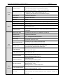
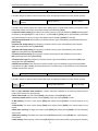
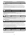
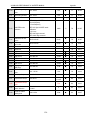
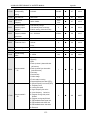
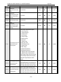
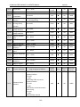
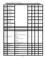
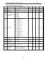
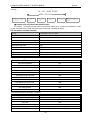
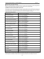
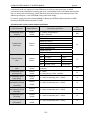
1.2 Technic criterion
Items
Criterion
3
AC80B HIGH-PERFORMANCE VC INVERTER MANUAL
Power
input
Output
Voltage,frequency
Single phase220V 50/60Hz
Three phase380V 50/60Hz Three phase220V 50/60Hz
Three phase660V 50/60Hz Three phase1140V 50/60Hz
Allowable fluctuations
Voltage:320V~440V; voltage unbalance rate:<3%;
Frequency:±5% aberration rate: as IEC61800-2 required
Inrush current
Lower than rated current
Power factor
≥0.94(with DC reactor)
Efficiency
≥96%
Output voltage
Output under rated condition:3 phase, 0~input voltage, inaccurancy<5%
Output frequency range
G type:0-320Hz
Output frequency
accuracy
Max frequency ±0.5%
Overload capacity
G type:150% rated current/1 min,180% rated current/10s, 200% rated
current/0.5s
Motor control mode
VC without PG, VC with PG, V/F without PG, V/F with PG
Modulate mode
Optimized SVPWM mode
Carrier frequency
0.6~15.0kHz,randomized carrier-wave
Speed range
VC without PG: rated load 1:100
VC with PG: rated load 1:1000
Steady speed accuracy
VC without PG: ≤1% rated synchronized speed
VC with PG: ≤0.02% rated synchronized speed
Starting torque
Flux VC without PG: when 0.5Hz, 180% rated torque
Flux VC with PG: when 0Hz, 200% rated torque
Torque response
Flux VC without PG: ≤20ms
Flux VC with PG: ≤10ms
Torque control accuracy
Flux VC without PG: ±10%
Flux VC with PG: ±5%
Frequency accuracy
Digit setting:max frequency×±0.01%
Analog setting:max frequency×±0.2%
Frequency resolution
Digit setting:0.01Hz
Anolog setting:max frequency×0.05%
DC braking capacity
Starting frequency:0.00~50.00Hz
Braking time:0.0~60.0s
Braking current:0.0~150.0% rated current
Torque upgrade capacity
Auto torque upgrade 0.0%~100.0%
Manual torque ungrade 0.0%~30.0%
V/F curve
5 modes: one user set V/F curve mode, one linearity torque characteristic
curve and three drop torque characteristic curve (1.3power, 1.7power, 2.0
powers).
Main
Control
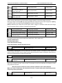
performance
Basic
functions
OVERVIEW
4
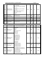
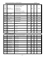
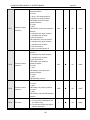
AC80B HIGH-PERFORMANCE VC INVERTER MANUAL
OVERVIEW
Acceleration/Deceleration
curve
2 modes: One linear Acceleration/Deceleration and two S curve
Acceleration/Deceleration. Four sets of Acceleration/Deceleration time unit
0.01s selectable longest time: 650.00s.
Rated output voltage
Rely on power supply voltage compensate function, while motor rated voltage
is 100%, set it at the range of 50-100%(output can not over input voltge).
Voltage auto-adjust
While power supply voltage fluctuates,it can auto-keep constant output
voltage.
Energy-saving running
According to load situation, auto-optimize output voltage to save energy.
Auto-limit current
Auto-limit the current while running to prevent overcurrent break trouble.
Instant power off
treatment
While instant power off, realize continual operation by bus voltage control.
Standard functions
PID control, speed track, power off restart, jump frequency, upper/lower
frequency limit control, program operation, multi-steps speed, swing frequency
running, RS485, analog output, frequency impulse output.
Frequency set channels
Keyboard digital set, keyboard potentionmeter, analog voltage terminal
VS1/VS2, analog current terminal AS, communication given and multi channels
terminal selection, master-slave channels combination.
Feedback input channel
Voltage terminal VS1/VS2, current terminal AS, communication given, pulse
input PUL.
Running command
channel
Operation panel given, external terminal given, communication given.
Input command signal
Start, stop, FOR/REV, JOG, multi-step speed, free stop, reset,
Acceleration/Deceleration time selection, frequency set channel selection,
exterior fault alarm.
Exterior output signal
One relay output, two collector output, 0~10V output,4~20mA
output,frequency pulse output.
Overvoltage, undervoltage, current limit, overcurrent, overload, electric
thermalrelay, overheat, overvoltage stall, data protection.
Protection function
Single file 4 digital tube display
Can monitor one state variable
Two file 4 digital tube display
Can monitor two state variables
LED display
Keyboard
display
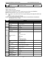
Environment
Parameter copy
Can upload or download function code information of inverter to realize fast
parameter copy.
State monitor
Output frequency, given frequency, output current, input voltage, output
voltage, motor speed, PID feedback, PID given value, module temperature,
input/output terminal condition.
Fault alarm
Ouve-voltage, under-voltage, over-current, short circuit, open phase, overload,
overheat, over-voltage speed lost, current limit, or data protection is destroyed;
Fault running state; Fault history.
Install place
Indoor, altitude ≤1000m,no corrosive air or direct sunshine
5
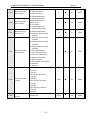
AC80B HIGH-PERFORMANCE VC INVERTER MANUAL
OVERVIEW
Temperature,
humidity
-10 ~ +40℃(hanging type)
-10 ~ +45℃(cabinet type)
20%—90%RH(no condensation)
Vibration
Under 20Hz≤0.5g
Store temperatue
-25—+65℃
Installation
Hanging type, cabinet type
Protection
IP20
Cooling mode
Forced cooling
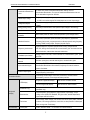
Table 1-1: Technic criterion
6
AC80B HIGH-PERFORMANCE VC INVERTER MANUAL
BEFORE USE
Chapter 2 Before Use
2.1 Purchase inspection
Pls check whether any package is damaged while receiving the product you ordered. If the package is ok, pls open it
and check the inverter. If damage caused in transport, it is not duty of company. But please contact or the transport
company immediately.
After checking the product, please also check if the model is the one you ordered.The model of the product is on the
nameplate “MODEL”column. If the model is not in accordance with your need, please contact the agent or the sales
departments in our company.
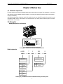
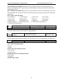
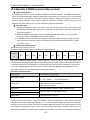
2.2 Nameplate
Nameplate position and content
MODEL
POWER SUPPLY
INPUT
OUTPUT
PRODUCTION
SERIES NO
Drawing2-1:AC80B series inverter nameplate position
Model explainatio
AC80B
(1)
T
3
2R2
G
(2)
(3)
(4)
(5)
Inverter series
motor adptor power(kw)
(pls refer drawing 2-1,2-2)
AC80B series
symbol
voltage
symbol
Inverter type
T
3-phase
G
Universal
S
single-phase
symbol
voltage
2
220V
3
380V
Drawing 2-2:AC80Bseries inverter nameplate meaning and naming rules
7
AC80B HIGH-PERFORMANCE VC INVERTER MANUAL
BEFORE USE
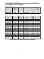
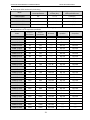
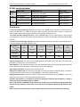
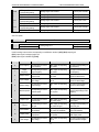
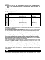
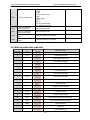
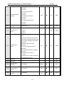
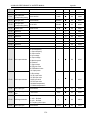
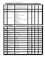
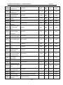
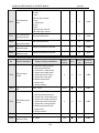
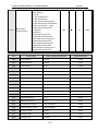
2.3 Standard models and rated parameters
Single phase 220V
Max adaptive
motor
Rated current
Model
Max
adaptive
motor
AC80B-S2-R40G
0.4kW
2.5A
AC80B-S2-1R5G
1.5kW
7A
AC80B-S2-R75G
0.75kW
4A
AC80B-S2-2R2G
2.2kW
10A
Model
Rated
current
Table 2-1:AC80B single phase 220V series inverter models and rated parameters
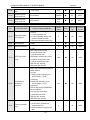
Three phase 380V
Max
adaptive
motor
Rated
current
AC80B-T3-110G
110kW
210A
AC80B-T3-132G
132kW
250A
AC80B-T3-160G
160kW
310A
AC80B-T3-185G
185kW
340A
13A
AC80B-T3-200G
200kW
380A
7.5kW
17A
AC80B-T3-220G
220kW
415A
11kW
25A
AC80B-T3-250G
250kW
470A
Model
Max adaptive
motor
Rated current
AC80B-T3-R75G
0.75kW
2.5A
AC80B-T3-1R5G
1.5kW
3.7A
AC80B-T3-2R2G
2.2kW
5A
AC80B-T3-004G
4kW
10A
AC80B-T3-5R5G
5.5kW
AC80B-T3-7R5G
AC80B-T3-011G
Model
AC80B-T3-015G
15kW
32A
AC80B-T3-280G
280kW
510A
AC80B-T3-018G
18.5kW
38A
AC80B-T3-315G
315kW
600A
AC80B-T3-022G
22kW
45A
AC80B-T3-355G
355kW
670A
AC80B-T3-030G
30kW
60A
AC80B-T3-400G
400kW
750A
AC80B-T3-037G
37kW
75A
AC80B-T3-450G
450kW
800A
AC80B-BT3-045G
45kW
90A
AC80B-T3-500G
500kW
860A
AC80B-T3-055G
55kW
110A
AC80B-T3-560G
560kW
990A
AC80B-T3-075G
75kW
150A
AC80B-T3-630G
630kW
1100A
AC80B-T3-090G
90kW
180A
AC80B-T3-700G
700kW
1260A
Table 2-2:AC80B three phase 380V series inverter models and rated parameters
8
AC80B HIGH-PERFORMANCE VC INVERTER MANUAL
INSTALLATION AND WIRING
Chapter 3 Installation and Wiring
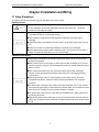
3.1 Safety Precautions
This chapter explains the warnings for safe use and stable running of the product.
Cautions in use
●While stall the inverter in the closed cabinet, please build in cooling fan, air-condition or other
cooling equipments to ensure the temperature at the air-in port below 40℃. So that the
inverter can work safely and reliably.
●While installing, please use cloth or paper cover the inverter to prevent metal dust, oil, water
and others.And remove it carefully after working.
● While operation, please follow the ESD regulations. Otherwise, the inverter may be
damaged.
● While multi inverters are installed in the same cabinet, enlugh space must be left for cooling
fan.
●Inverter can not work over rated range.Otherwise, the inverter may be damaged.
●While transporting the inverter, please hold the firm case. If only hold the pre-cover, there is
danger of inverter main body falling, injury or inverter damage.
Cautions in use motor
●Different motor has different max allowable running speed. Motor can not run over the max
allowable running speed.
●While inverter is running at low speed, the motor auto-cool effect is seriously worse. If motor
runs at low speed for long time, it will be damaged for overheat. If needed, please use special
motor for inverter.
●While constant speed machinery runs at unconstant speed, there maybe sympathetic
vibration. Please install vibration-proof rubber under motor rack or use jumping frequency
control function.
●While using frequency inverter or working frequency power supply to drive, the torque
characteristic are different. Please do confirm the torque characteristic of the equipment
connected.
●The rated current of shift gear motor is different from that of standard motor. Please confirm it
and choose the right frequency inverter. Moreover, please do switch the pole while the inverter
input current is 0. Otherwise it may bring inverter protection or damage.
●The rated current of diving motor is higher than that of standard motor, please confirm it and
choose the right inverter.
●While the wire between motor and inverter is long, the max torque of the motor will reduce for
voltage drop. So please use thick cable while the distance between the motor and the inverter
is long.
9
AC80B HIGH-PERFORMANCE VC INVERTER MANUAL
INSTALLATION AND WIRING
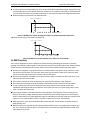
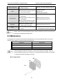
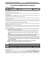
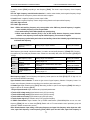
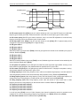
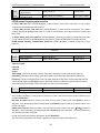
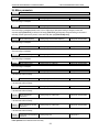
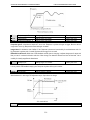
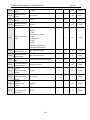
3.2 Treatment for inverter after longtime store
If the inverter store time is over one year, you must precharge the aluminium capacitor in the inverter again and install
the inverter after the aluminium capacitor characteristic recovering. For the specific method, please follow the grads in
belowing chart and give corresponding proportional voltage for every grad more than 30 mins while the inverter is
no-load.
If the input voltage of one grad is at the action critical point of contactor, fan or other equipments, please increase or
reduce the corresponding input voltage for the grad to avoid any component working under critical state.
Chart 3-1: treatment for inverter after longtime store
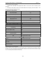
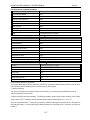
3.3 Inverter stable running environment
Installation environment is very important to the best use of this product for long time. Pls install this product in the
enviorment as the following chart requirement.
Environment
Install place
Requirement
Indoor without direct sunshine
Install temperature
-10 ~ +40℃(hanging type)
-10 ~ +45℃(cabinet type)
Store temperature
-20 ~ +60℃
Humidity
Surrounding
<95%RH, no condensation
Please install the inverter in place as follows:
● Place without oil mist, corrosive gases, flammable gase, dust or etc.
● Place without metal dust, oil, water or etc into inverter (please do not install inverter on
flammable material such as food and etc).
● Place without radioactive material or flammable material.
● Place without poisonous gases or liquid.
● Place with very little salification erosion.
● Place whihout direct sunshine.
Altitude
<1000m
Vibration
<10~20Hz:9.8m/s2
<20~55Hz:5.9m/s2
● Inverter can not be installed horizontally must be installed vertically.
Installation and
cooling
● Please independently install high heating equipments such as braking resistor and etc which
can not be installed in the same cabinet with inverter, installed at the air-in port of the inverter
is strictly prohibited.
Chart 3-1:AC80B series inverter running environment condition
10
AC80B HIGH-PERFORMANCE VC INVERTER MANUAL
INSTALLATION AND WIRING
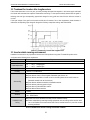
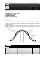
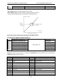
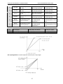
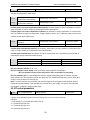
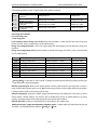
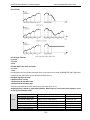
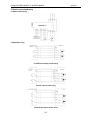
● In order to improve the product stability, pls do not use the inverter where temperature changes sharply. While using
in closed space such as control cabinet, please use cooling fan or air-condition to cool inverter to avoid temperature
over limit range. Please also prevent inverter from freeze, too low temperature may cause components freeze fault.
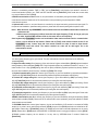
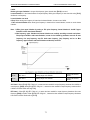
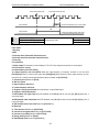
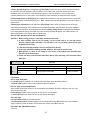
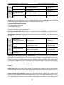
● Derate according to the chart while over temperature limit.
PERMIT OUTPUT CURRENT(%)
100
75
50
25
-10
0
10
20
30
40
50 TEMPERATURE(℃)
Chart 3-2:AC80B series inverter derating surve while over permit temperature temperature
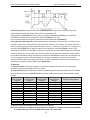
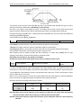
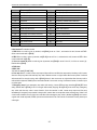
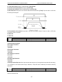
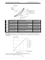
● Derate according to the chart while over altitude limit.
PERMIT OUTPUT CURRENT(%)
100
80
0
1000
2000
3000
4000
ALTITUDE(M)
Chart 3-3:AC80B series inverter derating surve while over permit altitude
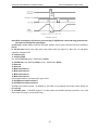
3.4 EMI Protection
The inverter is designed to be used in industrial environment with strong electromagnetic interference. Generally
speaking, if the installation quality is good, it is ensured that the inverter can work safely without fault. Please install the
inverter according to the following rules to ensure stable running and avoid electromagnetic interference impact.
● Ensure that all equipments in the cabinet have been connected reliably to the common Y-type earth point or earth
bus with thick and short cable. The motor earth should be as close as possible. Please do not connect the motor
case to the inverter earth terminal or the protective area of control system.
● Ensure that all equipments connected to the inverter have been reliably connected to the same earth net or Y-type
earth point with thick and short cable.
● The conductor has better to be flat and with multi core, what has lower resistance at high frequency.
● The cutting terminal should be as soigne as possible. Unshielded wire section must be as short as possible.
● In control cable wiring, it should be as far from the power supply cable and motor cable as possible. And
independent cable trough should be used. While the control cable must cross to the power supply cable or motor
cable, it should be 90º vertical cross.
● Ensure that the contactor in the cabinet has wave surge suppresser. Or‘R-C’damping circuit is connected to the
winding of AC contactor. Voltage dependent resistor corresponding to the winding voltage is used. And freewheel
diode or components such as voltage dependent resistor corresponding to the winding voltage are connected to DC
contactor. It is very important while contactor, controlled by output relay of inverter, acts frequently.
● Cable connected to motor should be shielded cable or armoured cable. The two barriers are earthed reliably by
cable grounding card.
● Build noise filters at the input side to reduce electromagnetic interference from other equipments at the power grid
side. The noise filter should be as close to the inverter power input terminal as possible. Meantime, the filter must
earth reliably as the inverter.
11
AC80B HIGH-PERFORMANCE VC INVERTER MANUAL
INSTALLATION AND WIRING
● Build noise filters at the output side to reduce radio interference and inductive disturbance. The noise filter must be
as close to the inverter output terminal as possible. Meantime, the filter must earth reliably as the inverter.
● Anytime, control circuit wire should be shielded cable.
● Add zero phase reactor in power supply wire near inverter input terminal and add zero phase reactor in the motor
wire near inverter output terminal to reduce electromagnetic interference to the inverter efficiently.
● Earthing Right and reliable earthing is the basic condition of safe and reliable running of the product. For right
earthing, please read the following notice carefully.
●In order to avoid electric shock, earthing cable should be the size as electric
equipment technic standard required and cable length should be as short as
possible. Otherwise, inverter leakage current will cause unstable potential of the
earthing terminal which is far from the earthing point, and electric shock accident will
happen frequently.
●Earth terminal must be earthing. Earth resistance must be below 10Ω. Otherwise,
there is danger of death.
● Please do not share earth cable with welder or other big current/pulse power
equipment. Otherwise, inverter will act abnormally.
●While multi inverters are used at the same time, please do not wind the earth wire to
loop-type. Otherwise, inverter will act abnormally.
Chart 3-4: multi AC80B series inverters united earthing
Chart 3-5:AC80B series inverter system earthing
Remark: motor must earth as close as possible. Motor case can not be connected to the inner earth terminal of the
inverter. It also can not share the earth net with the control system.
12
AC80B HIGH-PERFORMANCE VC INVERTER MANUAL
INSTALLATION AND WIRING
Shield of inverter power cable, motor cable, control cable Cable
Shielding layer (reticulate/armoured) should be winded reliably by cable earth card and fix to inverter earth piece by bolt.
Please refer to the following chart.
Chart 3-6:Cable earth card for cables earthing
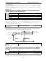
●Corresponding relationship between inverter/motor cable length and carrier frequency.
While cable distance between inverter and motor is long (especially low frequency output), cable voltage drop will make
motor torque reduce. Further more, cable HF leakage current will increase. Then inverter output current will increase,
that will cause inverter over-current trip. The current detection accuracy and running stability will be impacted. Please
follow as below chart to adjust carrier frequency according to the cable length. While the cable distance is over 100m,
please adopt distributed capacity reduce measure (Such as “no metal conductor covers cable”, “wire each phase cable
apart” and so on).
Cable length
<20m
20~50m
50~100m
>100m
Carrier frequency
0.6~16kHz
0.6~8kHz
0.6~4kHz
0.6~2kHz
Chart 3-2:Corresponding relationship between inverter/motor cable length and carrier frequency
13
AC80B HIGH-PERFORMANCE VC INVERTER MANUAL
INSTALLATION AND WIRING
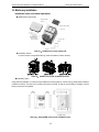
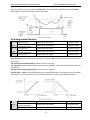
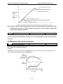
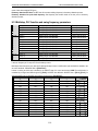
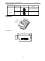
3.5 Machinery installation
Installation notice and related requirement
● AC80B inverter components
Chart 3-7:AC80B series inverter components
● Installation direction
To prevent inverter cooling effect reducing, please do install the inverter vertically.
Chart 3-8:AC80B series inverter installation direction
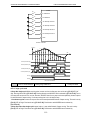
● Installation space
Single machine installation: to ensure enough ventilation and wiring space for inverter cooling, please follow installation
conditions as follows. The back of the inverter should stick to the wall. So that the surrounding air of radiator can flow
freely to ensure the cooling effect.
Chart 3-9:Single AC80B series inverter installation space
14
AC80B HIGH-PERFORMANCE VC INVERTER MANUAL
INSTALLATION AND WIRING
Multi inverters paratactic installation: while installing multi inverters in cabinet, please ensure installation space as
follows.
Chart 3-10: Multi AC80B series inverters paratactic installation space requirement
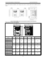
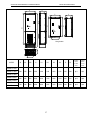
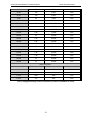
Dimension of inverter and keyboard
MODEL
H
D
D1
H1
W
W1
W
W1
H
H1
D
D1
INSTALLATION
APERTURE
122
112
182
171
154.5
145
ф5
159
147.2
246
236
157.5
148
ф5.5
122
112
182
171
154.5
145
ф5
159
147.2
246
236
157.5
148
ф5.5
195
179
291
275
167.5
158
ф7
AC80B-S2-R40G
AC80B-S2-R75G
AC80B-S2-1R5G
AC80B-S2-2R2G
AC80B-T3-R75G
AC80B-T3-1R5G
AC80B-T3-2R2G
AC80B-T3-004G
AC80B-T3-5R5G
AC80B-T3-7R5G
AC80B-T3-011G
15
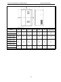
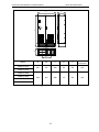
AC80B HIGH-PERFORMANCE VC INVERTER MANUAL
MODEL
AC80B-T3-015G
AC80B-T3-018G
AC80B-T3-022G
AC80B-T3-030G
INSTALLATION AND WIRING
W
W1
H
H1
H2
D
INSTALLATION
APERTURE
255
160
434
418
390
224
ф7
285
200
493
473
445
265
ф9
375
200
620
597
567
286
ф11
466
300
760
735
700
320
ф11
AC80B-T3-037G
AC80B-T3-045G
AC80B-T3-055G
AC80B-T3-075G
AC80B-T3-090G
16
AC80B HIGH-PERFORMANCE VC INVERTER MANUAL
INSTALLATION AND WIRING
D
W
H
H4
H3
WARNING
Risk of electric shock
Please follow the safety instruction s
in the manual before installation or
operation .
Wait 10 minutes for capacitor
discharge after disconnecting
power supply .
Do not connect AC power to output
terminals UVW.
To conform to
requirements,
make sure to ground the supply
neutral for 380V class .
After opening the manual switch
between the drive and motor,
please wait 10 minutes before
inspecting, performing maintenance
or wiring the drive .
H1
D
H2
W
WARNING
Risk of electric shock
Please follow the safety instruction s
in the manual before installation or
operation .
Wait 10 minutes for capacitor
discharge after disconnecting
power supply .
Do not connect AC power to output
terminals UVW .
To conform to
requirements,
make sure to ground the supply
neutral for 380V class .
After opening the manual switch
between the drive and motor,
please wait 10 minutes before
inspecting, performing maintenance
or wiring the drive .
W2
D1
Hang inverter
W1
MODEL
W
W1
W2
H
H1
H2
H3
H4
D
D1
installation
installation
aperture
aperture
of cabinet
of hang
inverter
inverter
AC80B-T3-132G
AC80B-T3-160G
590
350
430
1800
1600
1160
1050
1123
400
320
ф11
ф14
650
420
500
2200
2000
1318
1200
1276
400
321
ф13
ф16
750
400
600
2200
2000
1325
1200
1278
400
320
ф13
ф18
AC80B-T3-185G
AC80B-T3-200G
AC80B-T3-220G
AC80B-T3-250G
AC80B-T3-280G
17
AC80B HIGH-PERFORMANCE VC INVERTER MANUAL
INSTALLATION AND WIRING
D
W
WARNING
D1
H
Risk of electric shock
Please follow the safety instruction s
in the manual before installation or
operation.
Wait 10 minutes for capacitor
discharge after disconnecting
power supply.
Do not connect AC power to output
terminals UVW.
To conform to
requirements,
make sure to g round the supply
neutral for 380V class.
After opening the manual switch
between the drive and motor,
plea se wait 10 minutes before
inspecting, performing maintenance
or wiring the drive.
W1
MODEL
AC80B-T3-315G
AC80B-T3-355G
INSTALLATIO
W
W1
H
D1
D
800
400
2200
361
450
ф13
1200
600
2200
417
550
ф13
N APERTURE
AC80B-T3-400G
AC80B-T3-450G
AC80B-T3-500G
AC80B-T3-560G
Chart 3-3:AC80B series inverter dimension
18
AC80B HIGH-PERFORMANCE VC INVERTER MANUAL
INSTALLATION AND WIRING
Keyboard dimension
Mouth keyboard without box
104,5
54,5
Mouth keyboard with box
59,5
Chart 3-11:AC80B series inverter 1 line LED keyboard dimension
84,5
Chart 3-12:AC80B series inverter mouth for 1 line LED keyboard dimension
63.5
16.5
53.75
65.5
19.5
Chart 3-13:AC80B series inverter 2 line LED keyboard dimension
19
110.5
17.1
114.5
35.6
Mouth for keyboard
without box
70
64
Chart 3-14:AC80B series inverter mouth for 2 line LED keyboard dimension
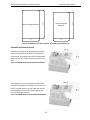
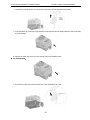
Dismantle and install tail-hood
Installation: First the tail-hood upwardly inclines around 15
degrees and inserts the top fixed flat into the fixed hole in
the front cover. Then slightly press the tail-hood downward.
While your hear "Ka", it means that the tail-hood is into the
place.
Chart 3-15:AC80B series inverter tail-hood installation
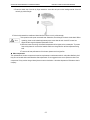
Dismantlement: At the tail of the frequency inverter, there
is a special dismantlement hole design. Put your finger into
the hole, upwardly pull the cover with a little force until the
buckle between the tail-hood and the crust tear off, and
then remove the tail-hood down.
Chart 3-16:AC80B series inverter tail-hood ismantlement
20
111
Mouth for keyboard with box
INSTALLATION AND WIRING
119
AC80B HIGH-PERFORMANCE VC INVERTER MANUAL
AC80B HIGH-PERFORMANCE VC INVERTER MANUAL
INSTALLATION AND WIRING
Dismantle and install keyboard
Chart 3-17:AC80B series inverter keyboard installation and dismantlement
3.6 Electric installation
This chapter explains the regulations that users have to obey to ensure safe use, best performance and reliable
running.
Safety attention
● Must earth reliably while inverter is running. Otherwise there is danger of casualty and
unstable inverter performance.
● To ensure safe running, only trained professional person can do installation and wiring
job.
● No operation under power connected state. Otherwise there is danger of electric shock
even death.
● Before operation, please cut all related equipments power, ensure that the main circuit
DC current has droped to safe range. And please operate after 5 mins.
● Control cable, power cable and motor cable must be separated. They can not be in the
same cable trough or cable rack.
● This equipment can only be used as the maker states. Please consult while using in
special case.
● No insulation test for the inverter or the related cable by HV insulation test equipment.
● If the inverter or the peripheral equipment (filer, reactor and etc) needs insulation test,
firstly 500V megohmmeter should be used to test the insulation resistance which should
not be lower than 4MΩ.
21
AC80B HIGH-PERFORMANCE VC INVERTER MANUAL
INSTALLATION AND WIRING
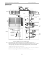
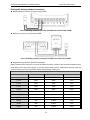
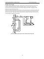
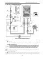
Standard diagram
● Standard diagram
external braking unit
R
breaker
contactor
input reactor
(-)
external DC reactor
external braking
resistance
(+)
(+)
PB (+)
short connect (note 1)
output reactor
P1
U
R
R
AC POWER
S
INPUT
S
V
V
T
T
W
W
U
M
~
AC80B
E
short connect (note 2)
+24V
PLC
forward
multi
function
connect
input
AC220V
3A/240VAC
5A/30VDC
X1
reverse
X2
forward
X3
reverse
X4
TA
Passive
connecter
output
TB
TC
double shielded cable
AC0V
free stop
X5
fault reset
X6
+24V
exterior fault output
X7
Y1
torque/speed control switch
X8
double shielded cable
COM
collector
open
output
Y2
COM
short connect (note 4)
pulse input
double shielded cable
10
0
J1
toggle
J2 switch
J3
_
mA
-
+
A02
GND
+10V
current analog input
(0~20mA)/(4~20mA)
AS
20
frequency
control input
PUL
double shielded cable
5
votage analog input
(0~5V)/(0~10V)
Note:
0
_
V
VS2
+
10
VR
VS1
-
A01
GND
GND
Chart 3-18:AC80B series inverter standard diagram
1.While install DC reactor, be sure to dismantle the short connector between terminal P1 and(+).
2.NPN or PNP transistor signal can be selected as input of multi-function input terminal(X1~X8). Inverter
built-in power supply (+24V terminal) or external power supply (PLC terminal) can be choosed as bias
voltage. Factory setting ‘+24V’ short connect with ‘PLC’.
3. Analog monitor output is special output of meters such as frequency meter, current meter, voltage meter
and etc. It can not be used for control operations such as feedback control.
4. As there are multi pulse styles, please refer to the line connect mode description details.
22
analog
monitor
output
AC80B HIGH-PERFORMANCE VC INVERTER MANUAL
INSTALLATION AND WIRING
● Auxiliary terminal output capacity
Terminal
Function definition
Max output
+10V
10V auxiliary power supply output,constitutes loop
with GND.
50mA
A01/A02
Analog monitor output, constitutes loop with GND.
As frequency,voltage signal, max
output 2mA
+24V
24V auxiliary power supply output,constitutes loop
with COM.
Y1/Y2
Collector open circuit output, can set the
action-object by programme.
TA/TB/TC
100mA
DC24V/50mA
Passive connector output,can set the action-object
by programme.
3A/240VAC
5A/30VDC
Chart 3-4:AC80B series inverter auxiliary terminals output capacity
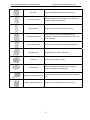
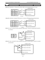
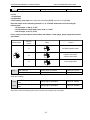
● Switch terminals connection function specification
Switch
Selectable
Picture example
terminal
position
Function
specification
J1
0.2--50kHz
frequency output
J2
0--20mA current
output
4--20mA current
output
J3
0--10V voltage
output
J4 J6
J5 J7
J4 connect
J 5 connect
J6 connect
J 7 connect
Out track selection
J4 J6 (with PG
card ) Inner track
selection J5 J7
(without PG card)
Chart 3-5:AC80B series inverter switch terminal connection function specification
23
AC80B HIGH-PERFORMANCE VC INVERTER MANUAL
INSTALLATION AND WIRING
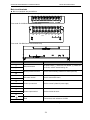
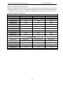
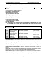
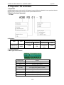
Main circuit terminals
● Main circuit terminals array and definition
Power under 18.5kW main circuit terminals array:
(-)(+) PB R S T U V W E
Power under 22~110kW main circuit terminals array:
R
S
T
P1 (+) (-) U
V
W
MOTOR OUTPUT
Power under 132~560kW main circuit terminals array:
Terminal
(-)
(+)
(+)
PB
P1
(+)
Name
Function definition
DC power terminal
DC power output, (-) means DC bus cathode, (+) means DC
bus anode, used for external braking unit.
Braking resistance terminal
Used for external braking resistance to realize quick stop.
DC reactor terminal
Used for external DC reactor.
Inverter input terminal
Used to connect 3-phase AC power supply.
Inverter output terminal
Used to connect the motor.
Earth
Earth terminal, earth resistance<10 OHM
R
S
T
U
V
W
E
Chart 3-6:AC80B series inverter main circuit terminals array and definition
24
AC80B HIGH-PERFORMANCE VC INVERTER MANUAL
INSTALLATION AND WIRING
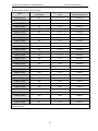
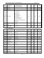
● 3-phase 380V machine main circuit wiring
Model
Main circuit terminals screw
specifications
Suggested fixed moment
(N·m)
Suggested Copper-core
cable specification mm2
AC80B-T3-R75G
M4
1.2--1.5
1.5mm2(14)
AC80B-T3-1R5G
M4
1.2--1.5
2.5mm2(12)
AC80B-T3-2R2G
M4
1.2--1.5
2.5mm2(12)
4mm2(10)
AC80B-T3-004G
M4
1.2--1.5
AC80B-T3-5R5G
M4
1.2--1.5
6mm2(9)
AC80B-T3-7R5G
M5
2--2.5
6mm2(9)
AC80B-T3-011G
M5
2--2.5
10mm2(7)
AC80B-T3-015G
M6
4--6
10mm2(7)
AC80B-T3-018G
M6
4--6
16mm2(5)
AC80B-T3-022G
M8
8--10
16mm2(5)
AC80B-T3-030G
M8
8--10
25mm2(3)
AC80B-T3-037G
M8
8--10
25mm2(3)
AC80B-T3-045G
M8
8--10
35mm2(2)
AC80B-T3-055G
M10
11--13
35mm2(2)
AC80B-T3-075G
M10
11--13
50mm2(1)
AC80B-T3-090G
M10
11--13
50mm2(1/0)
AC80B-T3-110G
M10
11--13
70mm2(2/0)
AC80B-T3-132G
M10
11--13
95mm2(3/0)
AC80B-T3-160G
M12
14--16
95mm2(4/0)
AC80B-T3-185G
M12
14--16
120mm2
AC80B-T3-200G
M14
17--20
150mm2
AC80B-T3-220G
M14
17--20
150mm2
AC80B-T3-250G
M16
20--23
185mm2
AC80B-T3-280G
M16
20--23
185mm2
AC80B-T3-315G
M16
20--23
240mm2
AC80B-T3-355G
M16
20--23
240mm2
AC80B-T3-400G
M16
20--23
300mm2
AC80B-T3-450G
M16
20--23
400mm2
AC80B-T3-500G
M16
20--23
400mm2
AC80B-T3-560G
M16
20--23
500mm2
Note: Here we suggest to use copper joins as mains electric connectors of machine over 185KW. Pls refer the cut
section area above.
Chart 3-7: Suggested cable diameter and fixed moment 3-phase 380V machine main circuit
25
AC80B HIGH-PERFORMANCE VC INVERTER MANUAL
INSTALLATION AND WIRING
● Single-phase 220V machine main circuit wiring
Model
Main circuit terminals
screw specifications
Suggested fixed
moment (N·m)
Suggested Copper-core
cable specification mm2
AC80B-S2-R40G
M4
1.2--1.5
1.5mm2(14)
AC80B-S2-R75G
M4
1.2--1.5
2.5mm2(12)
AC80B-S2-1R5G
M4
1.2--1.5
2.5mm2(12)
AC80B-S2-2R2G
M4
1.2--1.5
4mm2(10)
Chart 3-8: Suggested cable diameter and fixed moment single-phase 220V machine main circuit
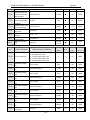
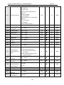
● Suggested main circuit components specification
Model
Contactor
specification
Breaker
specification
DC reactor
Input filter
Output filter
AC80B-T3-R75G
10A
10A
------
NFI-005
NFO-010
AC80B-T3-1R5G
10A
10A
------
NFI-005
NFO-010
AC80B-T3-2R2G
16A
15A
------
NFI-010
NFO-010
AC80B-T3-004G
16A
20A
------
NFI-010
NFO-010
AC80B-T3-5R5G
25A
20A
------
NFI-020
NFO-020
AC80B-T3-7R5G
25A
30A
------
NFI-020
NFO-020
AC80B-T3-011G
32A
40A
------
NFI-036
NFO-036
AC80B-T3-015G
40A
50A
------
NFI-036
NFO-036
AC80B-T3-018G
50A
60A
------
NFI-050
NFO-050
AC80B-T3-022G
50A
75A
DCL-50
NFI-050
NFO-050
AC80B-T3-030G
63A
100A
DCL-80
NFI-080
NFO-080
AC80B-T3-037G
80A
125A
DCL-100
NFI-100
NFO-100
AC80B-T3-045G
100A
150A
DCL-110
NFI-100
NFO-100
AC80B-T3-055G
125A
175A
DCL-125
NFI-150
NFO-150
AC80B-T3-075G
160A
200A
DCL-150
NFI-150
NFO-150
AC80B-T3-090G
220A
250A
DCL-200
NFI-200
NFO-300
AC80B-T3-110G
220A
300A
DCL-200
NFI-200
NFO-300
AC80B-T3-132G
250A
400A
DCL-300
NFI-300
NFO-300
AC80B-T3-160G
300A
500A
DCL-300
NFI-300
NFO-300
AC80B-T3-185G
400A
600A
DCL-400
NFI-400
NFO-400
AC80B-T3-200G
400A
700A
DCL-400
NFI-400
NFO-400
AC80B-T3-220G
630A
800A
DCL-500
NFI-600
NFO-600
AC80B-T3-250G
630A
1000A
DCL-600
NFI-600
NFO-600
AC80B-T3-280G
630A
1200A
DCL-600
NFI-600
NFO-600
AC80B-T3-315G
630A
1200A
DCL-800
------
------
AC80B-T3-355G
800A
1400A
DCL-800
------
------
AC80B-T3-400G
1000A
1600A
DCL-1000
------
------
26
AC80B HIGH-PERFORMANCE VC INVERTER MANUAL
INSTALLATION AND WIRING
AC80B-T3-450G
1000A
2000A
DCL-1000
------
------
AC80B-T3-500G
1000A
2000A
DCL-1200
------
------
AC80B-T3-560G
------
2000A
DCL-1200
------
------
Note: For DC reactor, input filter, output filter and other components specification details and circuit mode, please refer
chapter 7 “peripheral equipments and options”.
Chart 3-9: Suggested mains fittings for 3-phase 380V machine
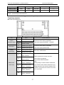
Control loop terminals
● Control loop terminals array
Sort
Passive
connection output
State output
Auxiliary
power supply
Multi-function
contact input
Terminal
Name
Function definition
TA
Normally-open contact
TB
Normally-closed contact
TC
Common contact
Y1
Collector open output 1
Y2
Collector open output 2
Can set the action-object by programme.
Max contact capacity:DC30V/50mA
+24V
Auxiliary power output +
COM
Auxiliary power output -
X1
Multi-function contact
input 1 (forward)
X2
Multi-function contact
input 2 (reverse)
X3
Multi-function contact
input 3(forward jog)
X4
Multi-function contact
input 4(reverse jog)
X5
Multi-function contact
input 5(free stop)
X6
Multi-function contact
input 6(fault reset)
Can set the action-object by programme.
Max contact capacity:3A/240VAC 5A/30VDC
Max output: 24VDC/100mA.
Build-in photoelectric converter can set the
action-object by programme.
Input condition: Max DC30V/8mA.
Note:
Factory setting is common-collector characteristic
input. If need common-emitter characteristic input,
please remove the short connector between“+24V”
and“PLC”, then use the short connector to connect
“PLC” and “COM”.
27
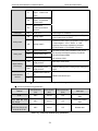
AC80B HIGH-PERFORMANCE VC INVERTER MANUAL
INSTALLATION AND WIRING
X7
Multi-function contact
input 7(exterior fault
input)
X8
Multi-function contact
input8(torque/speed
control switch)
PLC
Multi-function
contact input common
terminal
PUL
Pulse input
Pulse range:0.0~50.00kHz
Analog output 1
Can set the action and object by programme. Physical
type of output signal: 0~10VDC.
A02
Analog output 2
Can set the action-object by programme. Physical type
of output signal:0~10V 0~20mA 4~0mA
frequency pulse output, selectable by parameter
[F3.26] or switch J1 J2 J3 (Details in chart 3-5)
AS
Current analog input
VS1
Voltage analog input 1
VS2
Voltage analog input 2
+10V
Signal auxiliary power
supply terminal
Max output 10VDC/50mA
GND
Signal auxiliary power
supply terminal
Common auxiliary power of analog output, analog input
signal.
Pulse input
A01
Analog output
Analog input
Signal auxiliary
power supply
Communication
terminal
As inverter control signal or feedback signal, can set
the act range and response speed by programme?
VS1/VS2 resistance:89KΩ;
AS resistance: 250Ω.
A+
Communication terminal
A+
B-
Communication terminal
B-
RS485 communication port
Chart 3-10:AC80B series inverter control loop terminals array and definition
● Control loop terminal wiring specification
Terminal
Bolt specification
(mm)
Fixed moment
(N·m)
Cable specification
(mm2)
Cable type
A+ B-
M2.5
0.4~0.6
0.75
Twisted-pair shielded
cable
+10V GND A01 A02
VS1 VS2 AS
M2.5
0.4~0.6
0.75
Twisted-pair shielded
cable
+24V COM Y1 Y2 TA
TB TC PLC PUL X1 X2
X3 X4 X5 X6 X7 X8
M2.5
0.4~0.6
0.75
Shielded cable
Chart 3-11:Control loop terminal wiring specification
28
AC80B HIGH-PERFORMANCE VC INVERTER MANUAL
INSTALLATION AND WIRING
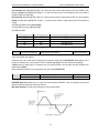
Braking unit (braking resistance) connection
● Braking resistance connection of machine below 18.5KW
Chart 3-19:Braking resistance connection of AC80B series inverter below 18.5KW
● Braking unit connection of machine above 22KW
Chart 3-20:Braking resistance connection of AC80B series inverter above 22KW
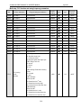
● Suggested braking resistance specification parameters
Braking resistance value and power in the chart are decided according to common inertia load and intermittent braking
mode. While used in large inertia occasion or long time frequent brake occasion, please adjust resistance value and
power according to the inverter specification and the rated parameter of braking unit.
Three-phase 380V
Motor power(kW)
Resistance value(Ω)
Resistance power(kW)
Braking moment (%)
0.75 kW
750Ω
150W
100%
1.5 kW
400Ω
300W
100%
2.2 kW
250Ω
400W
100%
4.0 kW
150Ω
500W
100%
5.5 Kw
100Ω
600W
100%
7.5 kW
75Ω
780W
100%
11 kW
50Ω
1,200W
100%
15 kW
40Ω
1,500W
100%
18.5 kW
32Ω
2,000W
100%
22 kW
28Ω
2,200W
100%
30 kW
24Ω
3,000W
100%
29
AC80B HIGH-PERFORMANCE VC INVERTER MANUAL
INSTALLATION AND WIRING
37 kW
20Ω
3,700W
100%
45 kW
16Ω
4,500W
100%
55 kW
13Ω
5,500W
100%
75 kW
9Ω
7,500W
100%
90 kW
6.8Ω
9,300W
100%
110 kW
6.2Ω
11,000W
100%
132 kW
4.7Ω
13,000W
100%
160 kW
3.9Ω
15,000W
100%
185 kW
3.3Ω
17,000W
100%
200 kW
3Ω
18,500W
100%
220 kW
2.7Ω
20,000W
100%
250 kW
2.4Ω
22,500W
100%
280 kW
2Ω
25,500W
100%
315 kW
1.8Ω
30,000W
100%
355 kW
1.5Ω
33,000W
100%
400 kW
1.2Ω
42,000W
100%
450 kW
1.2Ω
42,000W
100%
500 kW
1Ω
42,000W
100%
560 kW
1Ω
50,000W
100%
Single-phase 220V
Motor power(kW)
Resistance value(Ω)
Resistance power(kW)
Braking moment (%)
0.4 kW
400Ω
100W
100%
0.75 kW
200Ω
120W
100%
1.5 kW
100Ω
300W
100%
2.2 kW
75Ω
300W
100%
Chart 3-12:Suggested braking resistance specification parameters of AC80B series inverter
30
AC80B HIGH-PERFORMANCE VC INVERTER MANUAL
INSTALLATION AND WIRING
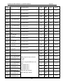
● Build-in braking unit max braking performance
Braking unit of AC80B series product with low power can be selected according to the suggested braking resistance
specification parameters in chart 3-11. In large inertia or long time frequent brake occasion, the moment maybe should
be increased. The max braking power is showed in the following chart, the range of which can not be over in use.
Otherwise the equipment maybe destroyed.
Three-phase380V
Inverter model
Motor power
Max braking current
Min resistance
AC80B-T3-R75G
0.75 kW
3.5A
200Ω
AC80B-T3-1R5G
1.5 kW
3.5A
200Ω
AC80B-T3-2R2G
2.2 kW
7A
100Ω
AC80B-T3-004G
4 kW
10A
75Ω
AC80B-T3-5R5G
5.5 Kw
10A
75Ω
AC80B-T3-7R5G
7.5 kW
14A
50Ω
AC80B-T3-011G
11 kW
17A
40Ω
AC80B-T3-015G
15 kW
23A
30Ω
AC80B-T3-018G
18.5 kW
28A
25Ω
Max braking current
Min resistance
Single-phase 220V
Inverter model
Motor power
AC80B-S2-R40G
0.4 kW
3.8A
100Ω
AC80B-S2-R75G
0.75 kW
3.8A
100Ω
AC80B-S2-1R5G
1.5 kW
6.5A
60Ω
AC80B-S2-2R2G
2.2 kW
10.5A
40Ω
Chart 3-13:AC80B series inverter build-in braking unit max braking power
31
AC80B HIGH-PERFORMANCE VC INVERTER MANUAL
INSTALLATION AND WIRING
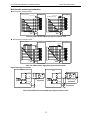
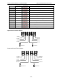
Multi-function contact input connection
● NPN transistor connection mode
use inner 24v power
+24V
factory short connect
AC80B
-
+
X1
X2
X2
X3
X4
X4
exterior
control
signal
X5
X5
X6
X6
X7
X7
X8
X8
COM
shielded cale
PLC
X1
X3
exterior
control
signal
AC80B
+24V
exterior 24v power
use exterior 24v power
PLC
COM
shielded cale
E
E
dismantle 24v and PLC connector
Chart 3-21: NPN transistor digital input signal connection mode
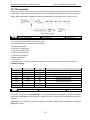
● NPN transistor connection mode
AC80B
use exterior 24v power
+24V
PLC
PLC
+
COM
COM
X1
X1
X2
exterior
control
signal
X2
exterior
control
signal
X3
X3
X4
X4
X5
X5
X6
X6
X7
X7
X8
shielded cale
AC80B
exterior 24v power
+24V
-
use inner 24v power
X8
shielded cale
E
E
Chart 3-22: NPN transistor digital input signal connection mode
Digital output signal connection
AC80B
AC80B
+24V
+24V
wind
exterior 24v power
COM
COM
COM
E
control exterior relay by inner 24V power of inverter
-
Y1
double shielded cable
COM
+
wind
Y1
E
double shielded cable
control exterior relay by inner 24V power of inverter
Chart 3-23:AC80B series inverter digital output signal connection mode
32
AC80B HIGH-PERFORMANCE VC INVERTER MANUAL
INSTALLATION AND WIRING
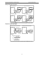
Analog output signal connection
A01 as 0~10V output indicator
A02 as 0~10V output indicator
5
5
AC80B
-
0
+
_
V
-
+
A01
10
10
_
V
0
AC80B
A02
GND
GND
double shielded cable
E
E
double shielded cable
A02 as 0.2~50KHZ output indicator
A02 as 0~20mA output indicator
10
25
-
0
kHz
+
A02
50
+
20
_
mA
AC80B
0
AC80B
-
A02
GND
GND
double shielded cable
E
double shielded cable
E
Chart 3-24:AC80B series inverter analot output signal connection mode
Connection of pulse input signal
Connection of passive pulse signal input
AC80B
+24V
Connection of active pulse signal input
Passive pulse
input bias resistor
AC80B
pulse signal source
pulse signal source
PUL
COM
E
PUL
PUL
COM
COM
STP cable
E
PUL
COM
STP cable
Explaination:
1.Bias resistor value calculation:
pulse voltage
R= 2
max pulse output current
1.Bias resistor power calculation:
2
P=
pulse voltage
bias resistor value
Chart 3-25: Pulse input signal connection mode of AC80B series inverter
33
AC80B HIGH-PERFORMANCE VC INVERTER MANUAL
INSTALLATION AND WIRING
Standby control system
Frequency inverter is composed of semiconductor, passive electronic component and driving part. All of them have
useful time, what means these parts may happen characteristic change or out of use while in normal working
environment. And it will cause product fault. To avoid production stopping led by the fault, we suggest to prepare
standby control system while use the inverter.
Chart3-23 is a standby control system for manual switch to power supply driving motor at inverter fault. Standby control
systems such as power supply Y/Δ step-down start way driving motor, power supply self-coupling reduction voltage
start mode driving motor, power supply soft start mode driving motor or standby inverter system can be chose to use
according the actual requirement and environment.
Chart 3-26: Standby control system of power supply directly driving mode
34
AC80B HIGH-PERFORMANCE VC INVERTER MANUAL
BASIC OPERATION AND TRIAL RUN
Chapter 4 Basic Operation and Trial Run
4.1 Safety Precautions
● No wiring while power supply is connected.Otherwise there is danger of electric
shock.
● No operation while the cover is open.Otherwise, there is danger of electric shock.
● Please ensure reliable earth. Otherwise,there is danger of electric shock and fire.
● Before wiring please cut power supply of allrelated equipments and ensure main DC
voltage in safe range. And please do operation after 5 mins.
● Only professional trained person is allowed to operate this product.
● Please do not dismantle the inverter cover while it is electrified. Otherwise, there is
danger of electric shock.
● Please do not touch the printed circuit board of the inverter while it is electrified.
Otherwise, there is danger of electric shock.
● Please ensure reliable mains cableconnection. If the mains cable is loose, thereis
danger of fire caused by joint overheat.
● Before electrifying, please check the power voltage again. Wrong power voltage can
cause fault or damage the inverter, even cause fire.
● Please do not install inverter on flammable material or attach flammable material to
the inverter. Before electrifying, please clear the surroundings.
● While operation, please follow the ESD regulations. Otherwise, the inverter maybe
damaged.
● Please don’t cut the power directly while the inverter drives the motor running. The
Important
power can’t be cut until the motor totally stop. Otherwise, the inverter maybe
damaged.
● Please don’t cut or connect motor while the inverter drives the motor running. The
motor can’t be cut or connect until the inverter output is 0. Otherwise, the inverter
maybe damaged.
● Control cable should be twisted-pair shielded cable. The barrier should be
connected to the inverter earth terminal reliably to prevent the inverter from
abnormal working.
● Unprofessional person can not operate, install, wiring, debug and maintain.
● Change, dismantle or maintain without permission may cause inverter damage. This
case is not in our quality assurance range.
35
AC80B HIGH-PERFORMANCE VC INVERTER MANUAL
BASIC OPERATION AND TRIAL RUN
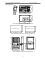
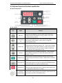
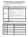
4.2 Keyboard layout and functions specification
● Keyboard appearance
● Key function
Key
Name
Menu key
Function
Enter menu while standby or running. Press this key to return while
modify parameter. While standby or running, press for 1 sec to enter
condition monitoring interface.
Confirm/modify
key
Press to modify parameter while in menu interface.Press again to confirm
after modifying. While standby or running, press to change LED
monitoring items at stop.
Up/down key
Select parameter group in menu interface. Modify parameter while in
modify interface. Modify given frequency,PID, given torque or magnetic
powder cluth given torque while at standby or condition monitoring state
(While given frequency, PID, given torque or magnetic powder cluth
given torque are set by keyboard and [F4.04])
Shift key
Select digit of function no modified by up/down key;Select parameter
digits modified by up/dowm key. Change LED monitoring items while
standby or running.
Forward run key
While run/stop is controlled by keyboard, press this key, the inverter
forward rotate and the indicator is always on. While reverse, the indicator
sparks.
Jog/reverse key
This key function can be defined by parameter [F4.02]. Press it, machine
reverses and indicator is off if this key is defined as REVERSE. Machine
will jog and indicator is on if this key is defined as JOG.
Stop/reset key
Machine stops if press it while run/stop is controlled by keyboard. Its
efficiency range is defined via function no [F4.03]. Inverter resets if press
it in fault state (no reset if fault is not solved).
Keyboard
potentionmeter
Can be used as input channel for given frequency, upper frequency limit,
given torque, given PID or PID feedback setting.
36
AC80B HIGH-PERFORMANCE VC INVERTER MANUAL
BASIC OPERATION AND TRIAL RUN
● Indicator light meanings
Name
Unit indicator
light
State
indicator light
Function
indicator light
State
Meaning
Hz
Spark
Digital display given requency.
Hz
On
Digital display output frequency.
A
On
Digital display actual output current.
V
On
Digital display input voltage.
V
Spark
Digital display output voltage.
S
On
S
Spark
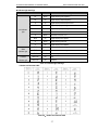
RPM
On
%
Spark
Time unit is second.
Time unit is ms, min, or h.
Digital display motor speed.
Digital display given PID.
%
On
Digital display PID feedback.
FWD
On
Inverter is forward rotating.
FWD
Spark
FWD
Off
Inverter stops.
REV/JOG
On
Jog.
REV/JOG
Off
Reverse.
Inverter is reverse rotating.
Chart 4-1: Indicator light meanings
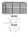
● Number and character table
Chart 4-2:Number and character table
37
AC80B HIGH-PERFORMANCE VC INVERTER MANUAL
BASIC OPERATION AND TRIAL RUN
● Basic LED operation
It displays frequency 50.00Hz when stop. Here F0.09=100.00 setting will be taken as an example to explain the
basic LED operation.
Chart 4-1: Basic LED operation
4.3 Basic operation
● Parameter initialization
After setting F0.19=1,parameter initialization is finished. Operation details as follows:
Chart 4-2: Parameter initialization
● Core control mode selections
Four core control mode selections:
0: VC without PG
1: V/F without PG
2: VC with PG
3: V/F with PG
Here we set F0.00=0(VC without PG control)as an example to introduce it
Chart 4-3: Core control mode selections
38
AC80B HIGH-PERFORMANCE VC INVERTER MANUAL
BASIC OPERATION AND TRIAL RUN
● Run command instructions
Four run command channels: 0: keyboard control, 1: terminal control,
2:RS485 communication control, 3: optional card. It can be set by F0.02.
Here we set F0.02=1(terminal control) as an example:
Chart 4-4: Run command instructions
It introducs terminal control two-wire 1, which is one kind of terminal control mode. For the other control modes,
please refer the chapter 9.
● Frequency command instructions
There are many kinds of requency command instruction selections. Please refer to chapter 9 for details. Here
we set F0.03=1(keyboard potentionmeter give frequency) as an example:
Chart 4-5: Frequency command instructions
● Start-up mode selections
Three start-up modes: 0: direct start-up, 1: braking firstly, then start by start-up frequency, 2: speed track and
start-up. Here we set Fa.00=2(speed track and start-up) as an example:
Chart 4-6: Start-up mode selections
● Stop mode selections
Three stop modes: 0: deceleration stop, 1: free stop, 2: all range DC braking stop. Here we set F1.07=1(all
range DC braking stop) as an example:
Chart 4-7: Stop mode selections
39
AC80B HIGH-PERFORMANCE VC INVERTER MANUAL
BASIC OPERATION AND TRIAL RUN
● Acceleration/deceleration time selections
There are 4 groups of acc/dec time. If no note, it is acc/dec time 1. Take setting F0.14=8.0(acc/dec time 1)as
example:
Chart 4-8: Acceleration/deceleration time selections
● Motor parameter setting
Set[F5.02](motor rated power), [F5.03](motor rated frequency),[F5.04](motor rated speed),[F5.05]
(motor rated voltage) according to the motor nameplate. Other parameter setting can be got by inverter
self-study.
Please refer to the following operation mode chart:
Chart 4-9: Motor parameter setting
● Parameter copy function selection
Set F4.05=1, send inverter parameter to keyboard and save:
Chart 4-10: Send inverter parameter to keyboard and save
40
AC80B HIGH-PERFORMANCE VC INVERTER MANUAL
BASIC OPERATION AND TRIAL RUN
Set F4.05=2, send keyboard parameter to inverter:
Chart 4-11: Send keyboard parameter to inverter and save
● Run monitoring setting
Chart 4-12: Run monitoring setting
41
AC80B HIGH-PERFORMANCE VC INVERTER MANUAL
BASIC OPERATION AND TRIAL RUN
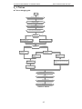
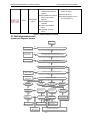
4.4 Trial run
● Trial run debugging guide
start
check power machine wiring
set F5.01 F5.06 according
the machine nameplate
press JOG/REV to jog run
check the direction,ifwrong,change wire after cut
power or set F0.16 to change the direction
no
rotate self-study,F5.12 is change to 1.Press
FWD,wait for self-study stop
static self-study,F5.12 is change to 2.Press
FWD,wait for self-study stop
VF control mode
yes
whether moror load
can break off
VC control mode
whether motor load
can break off
set F0.00=0,choose VC
control mode
set F0.00=1,choose VF
control mode
set F0.01=1,choose torque
control mode
set F0.01=0,choose speed
control mode
set giving torque F7.00,torque direction F7.02,set
torque limit F7.03/4,set torque control speed limit
F7.05-F7.08
set run frequency giving
channel F0.03=0
set run frequency F0.08
set run f command giving channel F0.02=0
press FWD to run
press stop/reset to stop
trial runn stop
Chart 4-13: Trial run
42
AC80B HIGH-PERFORMANCE VC INVERTER MANUAL
BASIC OPERATION AND TRIAL RUN
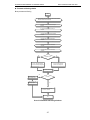
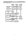
● Parameter self-tuning seletion
Motor parameter self-tuning
start
check inverter power wire connection,check wire connection
between inverter and motor,electrify
set number of motor poles F5.01 according to
nameplate
set motor rated power F5.02 according to
nameplate
set motor rated frequency F5.03 according to
nameplate
set motor rated speed F5.04 according to
nameplate
set motor rated votage F5.05 according to
nameplate
set motor rated current F5.06 according to
nameplate
yes
load break off test
no
set F5.12=2,static self-study,
press SET to g waitting state
set F5.12=1, rated self-study,press
SET to enter self-tuning waitting state
press FWD to start self-tuning
yes
self-tuning failture,
no parameter renew
fault alarm
detect fault cause,clear
fault ang try again
no
self-tuning finished,parameter
F5.07-F5.11 renewed
over
Chart 4-14: Parameter self-tuning selections
43
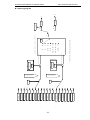
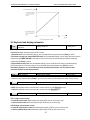
44
terminal VS1
RS485 communication
terminal PUL
analog AS given
=6
=5
=4
=3
=2
=1
=0
=12
=11
=10
=9
=8
=7
=6
=5
=4
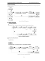
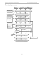
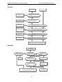
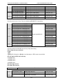
F0.05
F0.03
auxilliary channel
terminal VS2
=2
=3
frequency giving
channel selection
keyboard
potentionmeter
=0
=1
frequency giving main
keyboard number
giving
terminal switch
optional card
swig frequency
control
program control
PID control
up/down control
RS485 communication
terminal PUL
analog AS given
terminal VS2
terminal VS1
keyboard
potentionmeter
keyboard number
giving
K
f1*f2
=6
min{f1.f2} =5
F0.07
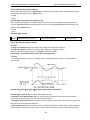
Chart4-15:frequency giving flow
mail giving frequency f2
F0.06
max{f1.f2} =4
=3
=2
f1-f2
=1
f2
=0
f1+f2
f1
f
auxilliary channels calculation synthesize
mail giving frequency f1
auxilliary
channel
K
F0.04
main channel
gain
f>f3
f≤f3
F0.11
output
frequency
output
frequency
f
f3
AC80B HIGH-PERFORMANCE VC INVERTER MANUAL
BASIC OPERATION AND TRIAL RUN
● Frequency giving flow
AC80B HIGH-PERFORMANCE VC INVERTER MANUAL
BASIC OPERATION AND TRIAL RUN
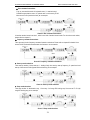
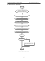
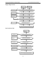
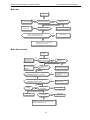
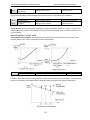
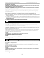
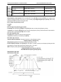
● Start/stop control flow
F
direct start
constant speed
set frequency
accelerate
start frequency
F1.00
F1.02
=0
T
=1
F1.03
=2
F
braking and start frequency start
constant speed
set frequency
accelerate
start frequency
Output frequency
constant speed run
F1.02
T
F1.04
F1.05 DC baaking F1.03
start
start frequency hold time
run command
stop
speed track restart
FA.08
decel eatel
stop
energy
baaking
F1.07
=0
=1
F
constant speed
set
frequency
terminal function 44
Xi
(Xi=X0 ~X7)
open
constant speed
stop output
DC baaking
braking current
start frequency
connect
F1.09
F1.08
terminal function 6
Xi
(Xi=X0~X7)
F1.10
open
braking waiting time
connect
free stop
Chart 4-16: Start/stop control flow
45
F1.11
T
braking time
AC80B HIGH-PERFORMANCE VC INVERTER MANUAL
BASIC OPERATION AND TRIAL RUN
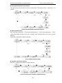
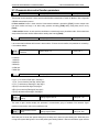
● Open-loop VC control(speed mode)
start
If change motor or electrify for the first time,
please self-tuning according to chart 4-14
set F0.00=0,choose VC control mode
set F0.01=0,choose speed control mode
according to chart 4-15,set giving frequency
set F0.02 to choose run command giving channel
according to chart 4-16,set start/stop control
according to system requirement,set F6.11 maximum output torque
trial run
whether control performance
reaches requirment
no
adjust F6 parameters to optimize VC
control performance,to improve output
torque/speed accuracy
yes
over
Chart 4-17: Open-loop VC control
46
AC80B HIGH-PERFORMANCE VC INVERTER MANUAL
FAULT DIAGNOSES AND PROCESSING
Chapter 5 Fault Diagnoses and Processing
This chapter explains the display contant and process of the inverter fault, alarm and operation fault. It also simply
explains the bad situation caused by inverter or motor fault and how to solve it. For the adjustment guide in trial run,
please refer to this chapter too.
5.1 Fault types
Type
Inverter action while fault happens
While inverter detect fault, the state likes this:
● Keyboard display character showing fault content.
● Inverter stops output. Motor free slide stops.
● While function F2.22/F2.23 is set as 3(output fault), Y1/Y2 terminals output valid
Equipment fault
open-collector digital output.
● While function F2.24 is 3(fault output), TA-TC terminals output open passive digital
output.
● While there is fault as OL, OC, SC, OV, UL2, if FA.15 is not 0, the inverter will restart
automatically after FA.16 setting time.
In certain application occasions, external related equipments fault signals are considered
in the inverter control system as usage of monitoring, protection or switch control. At this
time, if one multi function terminal is defied as “external fault”, the inverter stops output
alarm signal.
External fault
5.2 Fault information and details
Keyboard
display
Fault
code
Fault type
L.U.1
Too low while
stop
Treatment
Possible causes
● Power supply is too low
● Voltage detection
circuit
is abnormal
● Power supply is too
E.LU2
E.oU1
Acc
over-voltage
low
small, or there is big
impact current in the
power grid.
● Inner DC main contactor is
not closed.
● Power voltage fluctuation
over limit.
● Start running motor .
● Deceleration time is too
E.oU2
Dec
over-voltage
short.
● Load potential energy or
inertia is too large.
● Power voltage fluctuation
over limit.
47
fault.
● Seek support from factory.
● Power capacitance is too
Too low
voltage in run
● Check input power, eliminate
● Check
input input power,
eliminate fault.
● Improve power-supply system.
● Seek support from factory.
● Detect power voltage and
eliminate fault.
● Restart motor until it totally
stop.Set F1.00 as 1or 2.
● Prolong deceleration time
properly.
● Reduce load inertia or improve
inverter capacitance or add
braking unit.
● Detect input power and clear
fault.
AC80B HIGH-PERFORMANCE VC INVERTER MANUAL
E.oU3
E.oU4
Constant
speedovervoltage
Over-voltage
while stop
FAULT DIAGNOSES AND PROCESSING
● Power voltage fluctuation
over limit.
● Power voltage fluctuation
over limit.
● Acceleration time is too
E.oC1
Acc
over-current
short.
● Start running motor.
● V/F curve setting is not
suitable.Or torque boost
too high.
● Inverter capacitance is too
small.
● Deceleration time is too
E.oC2
E.oC3
Dec
over-current
Constant
speedover-cu
rrent
short.
● Load potential energy or
inertia is too large.
● Power voltage fluctuation
over limit.
● Sudden load change.
● Power grid voltage is too
low.
E.oL1
Motor
over-load
●
●
●
suitable.Or torque boost
too high.
Power grid voltage is too
low.
Unright overload
protection setting.
Locked-rotor run or too
heavy load.
Universal motor long time
low speed run.
● Load is too heavy.
● Acceleration time is too
E.oL2
E. SC
Inverter
over-load
System
abnormality
eliminate fault.
● Install input reactor.
● Check input power, eliminate
fault.
● Seek support from factory.
● Prolong acc time.
● Restart motor until it totally
stop.Set F1.00 as 1or 2.
● Reset V/F curve or torque
boost value.
● Select inverter with right
capacitance.
● Prolong deceleration time.
● Connect external braking
resistance or braking unit.
● Select inverter with right
capacitance.
● Check load change and
eliminate it.
● Check input power, eliminate
fault.
● V/F curve setting is not
●
● Detect input power voltage and
● Reset V/F curve or torque
boost value.
● Check input power, eliminate
fault.
● Unreasonable F5.06 setting.
● Adjust load or select inverter
with right capacitance.
● If need long low-speed
operation, please choose
special motor for inverter.
● Select inverter with right
capacitance.
short.
● Start running motor.
● V/F curve setting is not
suitable.Or torque boost
too high.
● Prolong acceleration time
● Acceleration time is too
● Prolong acceleration time
short.
● Restart motor util it totally stop.
Set F1.00 as 1or2.
● Reset V/F curve or torque
boost value.
properly.
● Short circuit between
48
● Check periphery equipments
AC80B HIGH-PERFORMANCE VC INVERTER MANUAL
FAULT DIAGNOSES AND PROCESSING
inverter output phases or
earth.
● Module is damaged.
● Electromagnetic disturb.
● Temperature is too high.
● Air channel is blocked.
E.oH1
Inverter
over-heat
● Fan connection parts is
loose.
● Fan is damaged.
● Temperature detection
circuit fault
● Temperature is too high.
● Air channel is blocked.
E.oH2
Rectifier
over-heat
● Fan connection parts is
loose.
● Fan is damaged.
● Temperature detection
circuit fault
● PID feedback breaks.
E.Fb1
PID feedback
over upper
limit
● PID feedback channels
parameter is set wrongly.
● Analog feedback channel
is abnormal.
● PID feedback breaks.
E.Fb2
PID feedback
over lower
limit
● PID feedback channels
parameter is set wrongly.
● Analog feedback channel
is abnormal.
and restart afrer fault
eliminating.
● Seek support from factory.
● Check system wiring, earth,
shield and deal as required.
● Make the environment meet the
requirement.
● Clear the air channel.
● Check and reconnect the wire
● Change the same new fan.
● Seek support from factory.
● Make the environment meeting
the requirement.
● Clear the air channel.
● Check and reconnect the wire.
● Change the same new fan.
● Seek support from factory.
● Check PID feedback wire.
● Check the PID feedback
channel parameter setting.
● Seek support from factory.
● Check PID feedback signal
wire.
● Check the PID feedback
channel parameter setting.
● Seek support from factory.
● Detection overtime
● Start static detection while
E.TE1
Motorstatic
detection fault
●
●
●
●
E.TE2
Moror rotation
detection fault
●
●
●
motor is running.
Capacitance difference is
too big between motor
and inverter.
Motor parameter setting
mistake.
Detect while motor is
running.
Detect with load.
Detection overtime
Capacitance difference is
too big between motor
and inverter.
Motor parameter setting
mistake.
49
● Check motor connection wire.
● Detect after motor stopping
totally.
● Change inverter model.
● Reset parameter according to
nameplate.
● Detect after motor stop totally.
● Re-detect without load.
● Check motor connection wire.
● Change inverter model.
● Reset parameter according to
nameplate.
AC80B HIGH-PERFORMANCE VC INVERTER MANUAL
FAULT DIAGNOSES AND PROCESSING
● Electromagnetic disturb in
E.EEP
Memory fault
LIFE
Reserved
E.ILF
Input side
open phase
memory period.
● EEPROM damage.
● resume load and save.
● Seek support from factory.
● Seek support from factory.
●
● Check 3-phase power supply
● 3-phase input power open
phase.
and the phase.
● Check 3-phase power supply
wiring.
E.oLF
Ouput side
open phase
● 3-phase output power
open phase
● Output earth terminal short
● Check 3-phase output voltage
and current.
● Check wiring.
E.Gnd
Output earth
E.HAL
Current
detection fault
● Detect circuit fault.
● Seek for technic support.
● Phase imbalance
● Check motor and wiring.
E. EF
Inverter
external fault
● Peripheral equipment fault
E.PAn
Keyboard
connect fault
circuit.
protection.
● Keyboard wire fault.
● Keyboard component
damage.
● Check wiring and insulation.
● Check peripheral equipment.
● Check keyboard wire.
● Seek support from factory.
● Unsuitable baud rate
setting.
E. CE
E.CPE
Rs485commu
nication fault
Parameter
copy fault
● Communication wire
● Set suitable baud rate setting.
breaks.
● Communication format
does not match upper
machine.
● Check communication wire.
● Parameter copy
● Check wire.
communication is fault.
● Copy keyboard is not
match the inverter.
● Select the specified external
● Set right communication format.
keyboard model.
● Communication between
E.ECF
Extend card
connection
fault
E.PG
PG card
connection
abnormal
extend card and
frequency inverter
overtime.
● Extend card does not
match frequency inverter.
● PG card and inverter
connection failure
50
● Check connector, and re-insert
wire.
● Choose the named card.
● Check the connection
AC80B HIGH-PERFORMANCE VC INVERTER MANUAL
FAULT DIAGNOSES AND PROCESSING
● Confirm the sensor state,if
● PID feedback upper limit
E.PID
of disconnection alarm is
improper
● PID feedback lower limit of
disconnection alarm is
improper
● PID feedback wiring
unreliable
● Sensor with feedback
failure
● Feedback input loop
failure
PID feedback
failure
broken, change it.
● Repair the wiring.
● Confirm the setting value of
[Fb.16] and [Fb.17].
Chart 5-1: Fault information and details
5.3 Fault diagnoses process
System fault diagnoses process
system fault
Clear short circuit
yes
Whether there is short circuit between outout terminal U/V/W and the motor
no
yes
Cable between output terminal U/V/W and motor
is too long that leakage current cause inverter protection
Short the cable or
add outout reactor
no
Clear disturbance
yes
Is there serious electromagnetic disturbance?
no
yes
While disconnect output wire and run,whether there is system fault alarm
no
no
yes
Connect load and
operate as follows
Three phase outout voltage balance is ok or not?
yes
Reduce load or
enhance power
yes
Whether overload or not?
no
no
no
Display E.SC
while start
Display E.SC
while stop
yes
Display E.SC while
machine stop
yes
yes
yes
yes
Torque enhance value
is suitable or not
no
no
Whether acceleration
time is too short
Whether deceleration
time is too short
yes
no
ACC time can be
prolonged or not
Dec time can be
prolonged or not
yes
yes
yes
yes
Reduce load change
or enhance power
no
Check braking mode,
seek tec support
Prolong setting time
Reduce load or
enhance power
Whether load
change suddently
yes
no
Torque enhance
valuecan be
reduced or not
Reduce
no
Display E.SC while
constant speed
Inverter fault or misaction caused by
noises.Pls find technic support
51
AC80B HIGH-PERFORMANCE VC INVERTER MANUAL
FAULT DIAGNOSES AND PROCESSING
Over current diagnoses process
Decelerate over
curent E.0C2
Accelerate over
curent E.0C1
yes
Constant speed
over curent E.0C3
Whether short circuit between output terminal
U/V/W and motor or earth circuit
Clear short circuit
no
no
no
yes
Reduce load or
enhance power
Whether load is too large
no
no
Whether torque
enhance value is too
Can be reduced?
no
no
yes
yes
Is deceleration
time set too short?
Is acceleration time
set too short?
Reduce the value
no
no
yes
yes
May fault or misaction
caused by noise.Please
find technic support
no
Whether load
changes suddently
yes
yes
Set longer acceleration
time or not?
Whether set longer
decelerationtime
yes
Prolong setting time
no
no
Reduce load change
or improve power
Check braking mode
and seek for technic support
52
Reduce load change
or improve power
AC80B HIGH-PERFORMANCE VC INVERTER MANUAL
FAULT DIAGNOSES AND PROCESSING
Over voltage diagnoses process
ACC over
voltage(OU1)
Reduce power voltage
into fixed range
DCC over
voltage(OU2)
Stop state over
voltage(OU4)
Constant speed
over voltage(OU3)
no
Fower votage in fixed range or not
yes
yes
yes
yes
Clear short circuit
Phase or earth short cirsuit bwteen U/V/W and motor
no
yes
Stop motor and restart.
Or DC braking,then
start(F1.00:1). Or speed
track start(F1.00:2)
no
no
Whether it stops while restart the motor
no
no
no
Whether act while load suddently changes to"0"
no
no
no
no
Whether DC circuit voltage of main loop is above protection value while act
Maybe inverter fault or
misact.Plese seek for
technic support
no
yes
yes
yes
yes
yes
yes
Whether act while
suddently stop ACC
Can prolong DCC time or not
no
no
yes
ACC time can be
prolong or not
prolong
no
yes
Load intertia can be reduced or not
Reduce
no
no
no
Whether used braking unit or DC braking function
yes
yes
yes
Please check braking unit and seek for technic support
53
Use braking unit or DC
braking function
AC80B HIGH-PERFORMANCE VC INVERTER MANUAL
FAULT DIAGNOSES AND PROCESSING
Supply voltage is too low
Voltage is too low
while stop(L.U.1)
Voltage is too low
while running(E.LU2)
yes
Whether power off,including instant power off
Restart after reset
no
no
yes
Change fault component
and correct bad contact
Is there any fault component or bad contact in power circuit
no
Modify power supply
system as required
no
no
Whether power voltage is in fixed range as required
yes
yes
yes
Is there any big load start or stop under the same power supply
no
no
no
votage between DC circuit P+ and N- in
main loop is over FA.10 setting or not
Adjust FA.10 setting
yes
yes
Maybe inverter fault.please seek for technic support
Inner inverter over heat
Inner inverter overheat
E.OH1,E,OH2
no
Change fan
Whether cooling fan works normally
yes
Maybe temperature ditection
circuit fault.please seek for
technic support
no
Whether temperature display(C-12)is
the same as the actual temperature
yes
Reduce load and
carried frequency
yes
Whether load and carried frequency
F0.17 setting are too high
no
yes
Clear the air-logged channel
Adjust the temperature to
the fixed range as required
Whether air cooling channels are air-logged
no
no
Whether the temperature is within the fixed range as required
yes
Maybe machine fault or misact.seek for technic support
54
AC80B HIGH-PERFORMANCE VC INVERTER MANUAL
FAULT DIAGNOSES AND PROCESSING
Over load
Inverter overload E.OL2
Motor overload E.OL1
no
Change externa
lthermal relay
Whether electric thermal relay overload
characteristic matches the motor overload
characteristic
yes
no
Whether electric thermal relay overload
relay setting FA.20 is suiable
Correct setting value
Reduce load or
improve capacity
yes
Restart after motor stop or
change start mode F1.00
to 1/2
yes
yes
Whether load too high
no
no
Whether the motor stops while restart
no
no
yes
Prolong ACC/DCC time
Whether ACC/DCC time is too short
no
no
no
Change torque improving
or V/F curve setting
Whether torque improving or V/F curve setting is suitable
yes
yes
Maybe inverter fault or misact.Please seek for technic support
No display
Inverter keyboard
LED no display
Whether keyboard
connect line is reliable
yes
Whether power indicater
linght on power board is
on or not
no
yes
no
yes
connect
Whether circuit breaker
at power side is connect to
contacter
no
Whether power input
terminals R/S/T is normal
connect
no
yes
Whether there is short connect
or DC reactor between terminals
P1 and P+l
Find our the fault cause
and clear the fault
no
yes
Maybe inverter fault or motor heat
caused by noise.Please find technic support
55
Short connect or
connect DC reactor
AC80B HIGH-PERFORMANCE VC INVERTER MANUAL
FAULT DIAGNOSES AND PROCESSING
Motor heat
motor heat
no
Adjust torque imporoving
value and V/F characteristic
yes
Whether torque improving and V/
F characteristic are suitable or not
no
Whether motor continuously
run at low speed
yes
yes
Reduce load or
improve capacity
Whether load is too large
Use special motor for inverter
no
yes
Whether output terminals U/V/W output
voltage /current three phase balance well
Maybe motor fault
no
Maybe inverter fault or motor heat caused by
noise.Please find technic support
Motor does not rotate
Motor does
not work
yes
Work after solving
fault and reset
Whether keyboard
displays fault information
no
yes
Have input command
signal or not
否
It works after checking
the cause and solving
the problem
no
Have input frequency
signal or not
It works after checking the
cause and slving the problem
yes
Whether upper frequency limit F0.11 or given frequency
is lower than the start frequency F1.01setting
yes
It works after correct the
upper frequency or given
frequency
yes
Is there voltage output on output terminal U/V/W
and three phase balance ok or not?
yes
Whether load
is too large
yes
no
Maybe inverter fault .Please
find technic support
yes
Whether wiring is
correct or not
no
Correct connect
no
Motor fault
Whether torque improving
value is suitable
no
yes
Maybe motor is locked because of too large load.Load
should be reduced.If there is braking or brake uni,
please check whether it is loose
56
Improve torque
improving value
AC80B HIGH-PERFORMANCE VC INVERTER MANUAL
PERIODIC OVERHAUL AND MAINTENANCE
Chapter 6 Periodic Overhaul and Maintenance
6.1 Safety Precautions
This chapter explains the safety rules in overhaul and maintenance.
● No operation under power connected state. Otherwise, there is danger of electric shock
even death.
● Before operation, please cut all related equipments power, ensure that the main circuit DC
current has droped to safe range. And please operate after 5 mins.
● No operation while cover/panel is dismantled. Otherwise there is danger of electric shock
even death.
● Do not dismantle the cover or PCB under power connected state. Otherwise there is
danger of electric shock death.
● Only professional person can maintain or change fittings. Otherwise, there is danger.
●Do not wear loose clothes when install, debug, maintain. Related protective tools and
safeguard should be adopted.
● Tighten screw according to named torque. If main circuit wire connection is loose, there is
danger of overheat fire.
● Machine and motor earth must be reliable. Otherwise, there is danger of electric shock if
touch the cover.
● While operation, please follow the ESD regulations. Otherwise, the inverter maybe
damaged.
● Do not change the circuit or structure of the inverter. Otherwise, the inverter maybe
damaged.
● Please confirm the rotate direction while no-load. Wrong direction can bring body injury or
huge wealth loss.
● Do not use damaged machine. Otherwise, there is danger of accident.
6.2 Overhaul
Frequency inverter is composed by semi-conductive components, passive electronic component and motive component.
All of these components have useful life. Even under normal working environment, some of the components can not
work after the life time. To avoid malfunction, daily checking, periodic overhaul, component changing and other
maintenance should be carried out to prevent. We suggest one overhaul every 3-4 months after installation. The
overhaul period should be shortened while under cases as below.
High temperature, high altitude;
Start and stop frequently;
AC power supply or load fluctuant badly;
With serious vibration or impact;
With dust, metal dust, salt, vitriol, chlorine;
Bad storage environment;
57
AC80B HIGH-PERFORMANCE VC INVERTER MANUAL
PERIODIC OVERHAUL AND MAINTENANCE
● Daily checking
To avoid machine damage and to prolong life time, please check the following items everyday.
Items
Checking content
Treatment
Power supply
Check if power supply meets the
requirement and whether there is
lack-phase.
Treat it as nameplate explains.
Surroundings
Check whether it meets the table3-1
requirement.
Make sure the problem and solve it.
Cooling system
Check whether the inverter or the motor
heat or change color abnormally and cooling
fan working state.
Check whether it overload. Tighten screw.
Check whether cooling fan is dirty or stall
rotate.
Motor
Check if there is abnormal vibration or noise.
Tighten machine and electric connection
and lubricate the machine components.
Load
Check whether output current is over the
rated value of the motor or the inverter and
has lasted for a period.
Make sure whether it overload and whether
the machine model is right.
No operation under power connected state. Otherwise, there is danger of electric shock death. Before
operating, please cut all related equipments power, ensure that the main circuit DC current has dropped to
safe range. And please operate after 5 mins.
● Periodic overhaul
Under normal state, one overhaul every 3 or 4 months is ok. Please confirm the actual overhaul period according to the
machine use condition and work circumstance while using the machine.
Main circuit
Items
Whole
Checking content
Treatment
Check insulated resistance;
Check circumstance.
Tighten and change bad component;
Clear and improve circumstance.
● Check whether the wire and
Electric connection
Mechanical connection
semi-conductive
component
connector color changes, whether
there is disrepair, crack color change
or aging in insulated layer.
● Check whether the connect terminals
are frayed, damaged or loose.
● Earth checking.
● Change bad wire.
● Check if there is abnormal vibration
●Tighten, lubricate and change the bad
or noise or something is loose.
● Check whether there is dust or
rubbish.
● If there is obvious out change?
● Fasten terminals and change bad
terminals.
● Measure earth resistance and fasten
earth terminals.
components.
● Clean operation environment
● Change damaged component
● Whether there is liquid leak, color
Electrolytic capacitor
change or crack. Whether the safety
valve outcrop, inflation, creak or
liquid leak.
58
● Change damaged component
AC80B HIGH-PERFORMANCE VC INVERTER MANUAL
Peripheral equipment
PERIODIC OVERHAUL AND MAINTENANCE
● Peripheral equipment outlook and
insulation checking.
● Peculiar smell color change, bad rust
PCB
and connector checking.
● Clear and change damaged component.
● Fasten connector
● Clear PCB
● Change damaged PCB
● Check whether the fan is damaged
or blocked up.
Cooling system
Keyboard
Motor
● Whether rubbish and dust is sticked
●Clean operation environment
to the heatsink .
● Is air inlet/outlet blocked? Or is there
something sticking to the inlet/outlet.
● Change damaged component
● Whether it is damaged. Check
whether display is complete.
● Check if there is abnormal vibration
or noise.
● Change damaged component
● Tighten machine and electric connection
and lubricate the machine components.
No operation under power connected state. Otherwise, there is danger of electric shock death. Before
operating, please cut all related equipments power, ensure that the main circuit DC current has droped
to safe range. And please operate after 5 mins.
6.3 Maintenance
All equipments and components have useful life. Right maintenance can prolong the lifetime. But it can not avoid
damage. Please change the components before their lifetime over.
Component
Useful lifetime
Fan
2~3year
Electrolytic capacitor
4~5 year
PCB
8~10 year
● Fan
While changing fan, please use original fan. You can contact company or the dealer. There are
inverter models with many fans in one machine. To prolong these machines’ lifetime, you had better
to change all fans while changing the cooling fan.
● Fan change method:
59
AC80B HIGH-PERFORMANCE VC INVERTER MANUAL
PERIODIC OVERHAUL AND MAINTENANCE
1. Install the fan vertically into the cover as shown in the picture (the label should face the outside).
2. Press the elastic clip of the fan by finger toward the inner side and insert the leading terminal of the fan vertically
by a little strength.
3. Insert the two elastic clips of the fan cover vertically into the fan installation slots.
● Fan dismantlement:
1. Pinch the two elastic clips of the fan and pull out. Then dismantle the fan cover.
60
AC80B HIGH-PERFORMANCE VC INVERTER MANUAL
PERIODIC OVERHAUL AND MAINTENANCE
2. Press the elastic clip of the fan by finger toward the inner side and pull out the leading terminal of the fan
vertically by a little strength.
3. Poke the clips toward the outside and detach the fan from the cover by a little strength.
1. No operation under power connected state. Otherwise, there is danger of electric shock death. Before
operating, please cut all related equipments power, ensure that the main circuit DC current has
droped to safe range. And please operate after 5 mins.
2. While the inverter is working, the heatsink temperature will be higher as the consumption. To prevent
from scald, please do not touch the heatsink and do not change the fan until the temperature being
safe.
3. To ensure the best performance of the inverter, please use the original fan.
● Other components
The replacement of the other components has strict requirements on maintenance technic and product familiarity. And
they can not be used without strict detection after replacement. So we suggest the user not to replace the other inner
components. If they need to change indeed, please contact to the dealer or the sales department of Shenzhen electric
company.
61
AC80B HIGH-PERFORMANCE VC INVERTER MANUAL
PERIPHERAL EQUIPMENTS AND OPTIONS
Chapter 7 Peripheral Equipments and Options
7.1 Safety Precautions
User must obey to the following safety rules and related requirements while using the peripheral equipments and
selecting components.
● No operation under power connected state. Otherwise, there is danger of electric shock.
●Before operation, please cut all related equipments power, ensure that the main circuit
DC current has droped to safe range. And please operate after 5 mins.
●No operation while cover/panel is dismantled. Otherwise, there is danger of electric
shock.
●Do not dismantle the cover or PCB under power connected state. Otherwise, there is
danger of electric shock.
●Only professional person can install, debug or maintain the peripheral equipments and
options. Otherwise, there is danger.
●Do not ware loose clothes when install, debug, maintain. Rated protective tools and
safeguard should be adopted.
●Do not change wire, dismantle jumping wire, optional card, or change cooling fan while
the inverter is running. Otherwise, there is danger of electric shock.
●Tighten screw according to named torque. If main circuit wire connection is loose, there is
danger of overheat fire.
● Earth of the peripheral equipments and options must be reliable to prevent human body
injury.
●While operation, please follow the ESD regulations. Otherwise, the inverter maybe
damaged.
●Do not cut the power supply while the inverter is outputting voltage. Otherwise, the
inverter maybedamaged.
7.2 Peripheral equipments
Normal peripheral equipments are showed as follows. To order the peripheral equipments, please consult our dealer or
sales department.
Peripheral equipment
Breaker
Functions
Protect power system and prevent malfunction impact other
equipments working when short-circuit happens. And
over-load protection.
Leakage current breaker
Earth protection prevent electric shock(suggest to use the
type which can prevent high-frequency leakage current)
Electromagnetic contactor
Separate power and inverter indeed and realize basic relay
control.
AC input reactor
Improve power side factor and isolate the noise disturbance
to the frequency inverter from the power side.
62
AC80B HIGH-PERFORMANCE VC INVERTER MANUAL
DC reactor
Input side noise filter
Braking resistor
PERIPHERAL EQUIPMENTS AND OPTIONS
Restrain ultraharmonics and improve power factor.
Reduce frequency inverter disturbance to the power and
reduce the power grid disturbance.
Passive energy consume unit of electric braking.
Consumption braking unit
Electric braking control unit, controlling the braking
resistance consume the regenerated electric power of the
motor efficiently.
Output side noise filter
Reduce the ouput side wire electromagnetic disturbance.
Standby system
Heat relay
0-phase reactor
Standby system for inverter malfunction.
Protect the motor while over load.
Reduce electromagnetic disturbance of the frequency
inverter (suitable for input/output side).
Main loop surge absorbable unit
Restrain surge voltage while main loop switch components
act.
Winding surge absorbable unit
Restrain surge voltage when the AC contactor acts.
63
AC80B HIGH-PERFORMANCE VC INVERTER MANUAL
PERIPHERAL EQUIPMENTS AND OPTIONS
7.3 The use of peripheral equipments
Chart 7-1: Peripheral equipments connetion fig
Note:
① Wiring breaker
To ensure wiring safe, protect power system and prevent malfunction impact other equipments working when
short-circuit happens, and protect while over-load, please do use wiring breaker between power supply and main
loop power input terminals R,S,T.
While choosing the breaker, the capacitance should be about 1.5-2 times of the rated output current of
the frequency inverter. Please compare the time characteristic of breaker and the characteristic of the
inverter protection (150% of the rated output current, one minute). Make sure there will be no skip.
Before main loop wiring, make sure to cut the breaker and electromagnetic contactor. Otherwise, there
is danger of electric shock.
② Leakage current breaker
The frequency inverter outputs peak voltage high-speed switch square wave, so there is high frequency leakage current.
For earth protection to prevent electric shock and leakage current fire, please install leakage current breaker. Usually,
64
AC80B HIGH-PERFORMANCE VC INVERTER MANUAL
PERIPHERAL EQUIPMENTS AND OPTIONS
one frequency inverter will bring 100mA leakage current (while the power cable length is 1m). If the length prolongs 1m,
there will be 5mA more leakage current. So please use leakage current breaker special for high frequency leakage at
the power input side of the frequency inverter. The factors which impact leakage current are as follows:
Capacitance of inverter;
Carrier frequency;
Motor cable type and wire length;
MI/RFI filter.
To protect human body and inverter, pleast choose leakage current breaker which can use AC/DC power and can reply
high frequency leakage current. There should be one leakage current breaker with more than 200mA sensitive current
for every frequency inverter. If the frequency inverter outputs different wave, the high frequency leakage current will be
higher, what will make the breaker malfunction. At this case, please take following treatments:
Improve the sensitive current of the leakage current breaker;
Reduce the carrier frequency of the inverter.
③ Electromagnetic contactor
Electromagnetic contactor is a peripheral equipment what is set to separate power and inverter connection. While
inverter protective function is acting or carring out emergency stop operation, the main loop power can be cut by
peripheral equipment. Please do not connect the electromagnetic switch or electromagnetic contactor to output circuit.
Otherwise, the inverter maybe damaged. While the power recovers after instant stop, if it needs to prevent the inverter
to auto-restart, please install electromagnetic contactor for control at the input side.
④ AC input reactor and DC reactor
To restrain current sharp change and high hypo harmonic current, it needs to use AC input reactor and DC reactor. It
can also improve power factor at the input side. In the following cases, AC input reactor or DC reactor must be used
(use both will bring better effect).
Need to restrain ultraharmonics current and improve power side factor;
Need to switch input phase capacitance;
When frequency inverter is connected to large capacitance power transformer (600kVA above);
Silicon-controlled converters such as DC motor driver are connected to the same power system.
The DC reactor, whose parameters are designed only for individual odd harmonic, is built inside AC80B series (90KW
above). If user has higher requirement on other harmonic restraint, please connect the external DC reactor (The DC
reactor is built inside AC80B series frequency inverter. At the same time, the external DC reactor connetion terminal is
fetched out. They are in series structure). Before connecting the external DC reactor, make sure to dismantle the short
connector between the terminals P1 and (+).
⑤ Surge restrainer
Surge restrainer is divided to winding surge restrainer and main loop surge restrainer according to the use position. Pls
choose the right one which is suitable for the occasion. The aim of surge restrainer installation is restraining the surge
voltage brought by switch components such as inductive load which is surrounding the frequency inverter
(electromagnetic contactor, electromagnetic relay, electromagnetic valve, electromagnetic winding, electromagnetic
detent). Do not connect the surge restrainer to the output side of the frequency inverter. Otherwise, the frequency
inverter will be damaged.
⑥ Input side noise filter
Rectifier bridge of the inverter is uncontrolled rectifier. And input current is discontinuous impulse current. So the
harmonic current noise signal, what flows to power wire from the inverter inner, maybe bring bad impact on the
surrounding machines (radio, phone, noncontact switch, sensor). This time, we suggest to instal input side noise filter to
lighten the noise into the power wire. Besides, it can also reduce noise from the power wire into the frequency inverter.
Please use the special noise filter for the frequency inverter and the connection wire between the filter
and the inverter should be as short as possible.
65
AC80B HIGH-PERFORMANCE VC INVERTER MANUAL
PERIPHERAL EQUIPMENTS AND OPTIONS
⑦ Output side noise filter
The frequency inverter outputs square wave with high-speed peak value voltage switch. So there is high-speed dv/dt
conver on the output cables that will produce a large number of radio disturbance and inductive signal. By installation
noise filter at the output side, the impact can be relieved. Please do not install the into phase capacitance and the noise
filter to the output circuit. Otherwise, there is danger of damage to the frequency inverter.
⑧ 0-phase reactor
0-phase reactor is used for reducing the electromagnetic interference of the frequency inverter, which is suitable for the
input side and output side. It equals to a three-phase common mode inductance. In actual use, according to the actual
magnetic core size and cable specification, it is better to make sure 3-5 circles winding ratio to bring the best
performance.
⑨ Braking reactor or braking unit
Renewable electricity consumption unit, please see the sixth part of the chapter three “electric installation”.
⑩ Heat relay
Please install the heat relay at the output side of the frequency inverter. When the motor enters into overload state, it
will cut the power source to protect the motor. While using one frequency inverter to drive one motor, it is unnecessary
to install heat relay. The motor overload protection current [FA.20] of the frequency will work. While using one frequency
inverter to drive multiple motors or the motor is drove directly by the power grid, please install heat relay between the
inverter and the motor. While installing the heat relay, please design to cut the sequence control circuit of the MC at the
main loop iuput side by the connection spot of the relay or design to input the heat relay action into the frequency
inverter as the exterior malfunction. And please pay attention to the following tips to avoid heat relay malfunction and
motor overheating at low speed.
Run at low speed
One frequency inverter run multiple motors
Motor cable is very long
Detect malfunction mistakenly for carrier frequency is too higher.
Low speed and heat relay
In normal case, the heat relay is suitable for the universal motor. While using the frequency inverter to run the universal
motor (standard motor), the motor current is 5-10% higher, comparing with the commercial power supply. Besides, at
low speed, even in the motor rated current range, the cooling capability of the fan drove by the motor axis will reduce,
which will bring motor overheat. So please set the motor overheat protection current [FA.20] in the frequency inverter to
be valid.
Motor cable is longer
While the motor cable is longer and the carrier frequency is higher, impacted by the leakage current, the heat relay
maybe malfunction. To avoid it, please reduce the carrier frequency or set higher detection value of the heat relay.
Before enhance the detection value, do confirm whether there is other cause for the motor overheat. Otherwise, there is
danger.
66
AC80B HIGH-PERFORMANCE VC INVERTER MANUAL
QUALITY GUARANTEE
Chapter 8 Quality Guarantee
8.1 Guarantee time and range
Guarantee time
Users can enjoy the following “three guarantee” service from the day of buying products if meeting products quality
problem:
●We guarantee for repair, return and replacement for one month after delivery;
●We guarantee for repair and replacement for two months after delivery;
●We guarantee for repair for eighteen months after delivery;
●The articles above do not apply to export.
Guarantee range
Installation and debugging:In principle, it should be carried by users. Our company provides technical support. But we
can afford installation and debugging service with charge.
On-site diagnosis: In principle, it should be carried by users. Our company gives technical support. But we can afford
on-site diagnosis service with charge. According to diagnosis, if it is our liability, it will be free.
Malfunction maintain: While meeting malfunction, if it is quality problem and within guarantee time, we will repair free of
charge. The malfunctions, caused by the reasons mentioned as follows, can only enjoy the paid service even if the
product under warranty:
●The malfunctions caused by improper storage or faulty operation which are not in compliance with this user
manual.
●The malfunctions caused by unauthorized transformation.
●The malfunctions caused by over-range operation.
● Have over guarantee time.
●The malfunctions caused by nature causes.
8.2 Liability exemption
Our company only takes on the liability according to our guarantee time and range. If you need more liability guarantee,
you should buy proper commercial insurance from insurance company in advance. The other extended loss caused by
malfunctions of our product is not within our guarantee range. Cases as follows, regardless of whether it is within
guarantee time,it is not within our guarantee range. If need service, you has to pay for it.
●The malfunctions caused by improper storage or faulty operation.
●The malfunctions caused by unauthorized transformation.
●The malfunctions caused by over-range operation.
●Have been over guarantee time.
●The malfunctions caused by nature causes.
●User has not paid off the payment according to the contract.
8.3 Product application
●This product is not designed and produced for the case of vital importance.
● If need to apply this product in manned mobile machine, medical, aerospace , unclear energy, electric power,
devices or system for submarine communications transit, please contact the sales department of our company.
We do not take on the liability of the accident while this product is used in these cases without authorization.
●This product is produced under strict quality management. But we can not ensure that there will be no
malfunction. If the user requires more safety requirement and reliability, standby device should be deployed. If
the user need more guarantee, proper commercial insurance should be considered.
67
AC80B HIGH-PERFORMANCE VC INVERTER MANUAL
FUNCTION PARAMETER SPECIFICATION
9 FUNCTION PARAMETER SPECIFICATION
9.1 Basic parameters
F0.00
Control mode
Setting range: 0-3
Factory set: 0
0: VC without PG means vector control mode without speed sensor. It is used for all variable speed control. Please set
this mode while need high accurate speed control.
Under this mode, even no motor feedback signal, torque can response quickly. The motor can gain large torque even at
low running speed.
1: V/F without PG control voltage/frequency ratio, all can change speed. It is specially suitable for one frequency drive
multi-motor application. It improves the current speed control system.
This mode is used for all speed control system while quick response and right speed control are unnecessary, or motor
not clear or can’t self study.
2: VC with PG means vector control mode with speed sensor. This mode is used for all speed control system that
torque response is quick and needs high performance torque control. It can be for high accurate speed control to 0
speed. To receive motor speed feedback signal, please use optional PG card.
It is mainly used for application requires strict control performance, such as: high accurate speed control system, high
accurate torque control, simple servo control and so on.
3: V/F with PG can be used for simple speed feedback control. Please set this mode when need slow respond, but
right speed control, especially occasions that PG feedback does not install on motor spindle, or occasions that motor
not clear or can’t self study.
Note: 1. PG: usually means photoelectricity inspects speed pulse encoder. While use other speed inspect card,
other sensor can be used for speed feedback.
2. While choose VC control mode, before the first running, it has to input right motor parameters and
motor parameters self adjust to gain right motor parameter. Please refer to details of F5 parameter
groups.
3. Rightly setting VC control parameters to ensure good stabile and dynamic control performance. For
VC control parameter setting and adjustment, please refer to details of F6 parameter groups.
4. While choose VC control mode, all inverters can only drive one motor, and the capacitance rating
difference between the inverters and the motor can’t be too large. The inverter can be 2 rating bigger
or 1 rating smaller than the motor. Otherwise, it will descend the control performance. Or the drive
system can’t run normally.
5. While choose VC with PG or V/F with PG control, must rightly set [F5.15--F5.17] parameters.
6. While choose V/F control mode, must rightly set V/F control parameters F8.
F0.01
Reserved
F0.02
Run command channel
Setting range: 0-3
Factory set: 0
It is channel for inverter receiving run and stop order and run direction. It is only used for starting and stopping control
under torque control.
0: Keyboard control Inverter run and stop is controlled by keyboard key FWD, REV/JOG, STOP/RESET. REV/JOG
key is defined as reverse while [F4.02] set as “0” and jog while [F4.02] set as “1”. Please refer to details of [F4.02].
1: Terminal control Factory default as two line mode 1 control mode. Under two line mode 1, inverter run, stop and
68
AC80B HIGH-PERFORMANCE VC INVERTER MANUAL
FUNCTION PARAMETER SPECIFICATION
direction is controlled by whether “FWD” or “REV” set for [F2.00-F2.07] “multi function input terminal” connects to
control board terminal (COM) or not. “FWD” and “REV” definition refer to [F2.00-F2.07]. While under other control mode,
run, stop and direction refer to [F2.12].
2: RS485 communication control Inverter run, stop and direction is controlled by the signal received by RS485
communication terminal. Details refer to Fd communication control parameter group and appendix 2: RS485
communication protocol.
3: Optional card Inverter run, stop and direction is controlled by the signal received by optional card input signal. For
the optional card installation, parameter setting and soon, please refer use manual packing with the optional card.
Note: 1. While fault reset, key STOP/RESET, control terminal reset order and RS485 communication terminal are
valid reset order.
2. While inverter input frequency is 0Hz or lower than min output frequency [F1.26]. As long as you input
run order, keyboard FWD indicator will be on, the motor will run as 0 frequency.
Clew: keyboard key STOP/RESET function can be selectable. Under exterior terminal control or communication
control, it can be defined as stop function. Please refer to [F4.03]. Under exterior terminal control, if use
STOP/RESET to stop, inverter stops and close exterior terminal run order. It needs to input exterior
terminal stop order and unlock. The exterior terminal run order will be valid again. So is the
communication control.
F0.03
Frequency give main channel selection
Setting range: 0-12
Factory set: 0
It is used to select frequency given gain channel. The main and assistant channels relationship can be defined by
parameter [F0.07].
0: Keyboard number setting Given frequency of the main channel is given and modified by [F0.08] keyboard numbers
setting frequency. While parameter [F4.04] LED “0” digit “keyboard up/down key modification selection” is set as “1”, no
matter inverter is run or stop, [F0.08] setting value can be quickly modified by keyboard up/down key directly. Whether
store the value modified by the shortcut key is decided by [F4.04] LED “00”digit.
1: Keyboard potentiometer given Main channel given frequency is given and modified by keyboard potentiometer.
Please refer to [F4.07-F4.10] details for the relationship between keyboard potentiometer and frequency.
2: Terminal VS1 voltage analog Main channel given frequency is given and modified by (VS1) input analog. Please
refer to [F3.00-F3.04] details for the relationship between input analog filter time and frequency.
3: Terminal VS2 voltage analog Main channel given frequency is given and modified by (VS2) input analog. Please
refer to [F3.05-F3.09] details for the relationship between input analog filter time and frequency.
4: Terminal AS current analog Main channel given frequency is given and modified by (AS) input analog. Please refer
to [F3.10-F3.14] details for the relationship between input analog filter time and frequency.
5: Terminal pulse signal Main channel given frequency is given and modified by (PUL) input pulse signal. Please refer
to [F2.16-F2.21] details for the relationship between input pulse signal and frequency.
6:RS485 communication port: Main channel given frequency is given and modified by the signal accepted by RS485
communication port (A+) and (B-). Please refer to Fd communication control parameter groups and appendix 2: RS485
communication protocol details.
7: UP/DOWN control Main channel given frequency is given and modified by if UP terminal is connected to DOWN
terminal or not, what is set by multi-function terminals (X1-X8). Anyone of the (X1-X8) terminals can be defined as UP
and DOWN. Please refer to [F2.00-F2.07] details. UP, DOWN store and clear mode after adjustment can be set by
[F2.22]. Please refer to [F2.22] details. ACC AND DEC of UP/DOWN control running given frequency is set by [F2.23].
UP/DOWN variation frequency can be cleared to 0 at any time by “UP/DOWN clear 0” terminal. Details see
[F2.00-F2.07].
69
AC80B HIGH-PERFORMANCE VC INVERTER MANUAL
FUNCTION PARAMETER SPECIFICATION
8: PID control givenThis channel is selected for PID closed loop control system. PID control is the control mode
makes feedback the same as the target. Refer to PID control parameters “Fb”.
Under this mode, while [F4.04] LED “0” digit is set as 3 by keyboard UP/DOWN key; [Fb.01] can be modified by
UP/DOWN key. Whether save the modification is decided by [F4.04] LED “00” digit.
PID control state and trait are changed by multifunction terminals. Details refer to [F2.00-F2.07].
9: Program control (PLC) given Main channel given frequency and frequency running direction is controlled by inner
simple PLC control. Max 15 steps speed can be process control. Details see “FC” multi step, PLC function and swing
frequency parameter group. If one step speed running time is set as “0”, it will jump over this step. It is convenient to set
step speed. While [F0.07] LED “00” digit is 0, frequency control direction is invalid. While [F0.16] is set as 2—REV
forbid and any step direction is set as REV, this step run as 0 speed. PLC and multi steps speed are both for frequency
inverter vary speed and run under certain rules. Under multi steps running, step switch and direction change is control
be the different combination between multi step control terminal and COM defined by multifunction input terminals. PLC
not only can define one cycle of multi steps frequency in the function parameters. It can also define the run time,
direction, ACC/DEC time and cycle mode of multi steps in the function parameters. Multi steps control terminal can be
defined by any multifunction terminal. Details refer to [F2.00-F2.07].
10: Reserved
11: Optional card Main channel given frequency is controlled by input signal by optional card. For optional card
installation, parameter setting please refers to user manual.
12: Terminal switch Frequency setting main channel is selected by frequency selection terminal which can be defined
by any multi function terminal. See [F2.00-F2.07] please. Relation table between terminal state and frequency setting
channel:
Frequency
Frequency
Frequency
Frequency
setting selection
setting selection
setting selection
setting selection
Frequency setting channel
terminal 4
terminal 3
terminal 2
terminal 1
OFF
OFF
OFF
OFF
Keyboard number give
OFF
OFF
OFF
ON
Keyboard potentiometer give
OFF
OFF
ON
OFF
Voltage analog VS1 give
OFF
OFF
ON
ON
Voltage analog VS2 give
OFF
ON
OFF
OFF
Voltage analog AS give
OFF
ON
OFF
ON
Terminal pulse PUL give
OFF
ON
ON
OFF
RS48 communication give
OFF
ON
ON
ON
UP/DOWN control
ON
OFF
OFF
OFF
PI control give
ON
OFF
OFF
ON
PLC give
ON
OFF
ON
OFF
Reserved
ON
OFF
ON
ON
Optional card
Combination details refer to multistep speed time order of “FC” parameter.
Note: valid combination of frequency selection terminal is 0-11(algorism). Frequency inverter will output 0.00Hz
if not within this range. “OFF”in the table means invalid. “ON” means valid.
70
AC80B HIGH-PERFORMANCE VC INVERTER MANUAL
F0.04
Main channel gain
FUNCTION PARAMETER SPECIFICATION
Setting range: 0.000-5.000
Factory setting: 1.000
It is used to magnify or reduce the main channel input signal, can adjust given frequency of main channel at prorate.
F0.05
Frequency give auxiliary channel
selection
Setting range: 0-6
Factory setting: 1
It is used to select auxiliary channel for frequency given, directly control or impact output frequency of frequency inverter.
Relationship between main channel and auxiliary channel can be defined by [F0.07].
0: Keyboard number setting Given frequency of auxiliary channel is given and modified by [F0.08] keyboard number
set frequency. While [F4.04] LED “0” digit is set as 1 by UP/DOWM key, [F0.08] can be quick modified by UP/DOWN
key whether frequency inverter is running or stop.Whether save is decided by [F4.04] LED “00” digit.
1: Keyboard potentiometer Given frequency of auxiliary channel is given and modified by potentiometer.Detail refer to
[F4.07-F4.10].
2:Terminal VS1 voltage analog Given frequency of auxiliary channel is given and modified by control terminal
(VS1). Input analog.Detail refers to [F3.00-F3.04].
3:Terminal VS2 voltage analog Given frequency of auxiliary channel is given and modified by control terminal
(VS2).input analog.Detail refer to [F3.05-F3.09].
4:Terminal AS current analog Given frequency of auxiliary channel is given and modified by control terminal
(AS).input analog.Detail refer to [F3.10-F3.14].
5:Terminal pulse signal Given frequency of auxiliary channel is given and modified by control terminal (PUL).input
analog.Detail refer to [F2.16-F2.21].
6: RS485 communication Given frequency of auxiliary channel is given and modified by signal accepted by RS485
communication port (A+) and (B-) input analog.Detail refer to Fd communication control parameter group and appendix
2: RS485 communication protocol.
F0.06
Auxiliary channel gain
Setting range: 0.000-5.000
Factory set: 1.000
It is used to magnify or reduce the main channel input signal, can adjust given frequency of main channel at prorate.
F0.07
Frequency give channels combinations
mode
Setting range: 0000-0016
Factory set: 0000
LED “0” digit: ombination mode selection It is used to select the combination of the main input channel and the
auxiliary input channel of the give frequency.
0: Main channel valid Only main channel [F0.03] is valid, auxiliary channel [F0.05] is invalid.
1: Auxiliary channel valid Only auxiliary channel [F0.05] is valid, main channel [F0.03] is invalid.
2: Main+auxiliary The sum of main channel [F0.03] add auxiliary channel [F0.05] is the output frequency of the
inverter.
3: Main-auxiliary The result of main channel [F0.03] minus auxiliary channel [F0.05] is the output frequency of the
inverter.
4: MAX {main, auxiliary} The bigger one of main channel [F0.03] and auxiliary channel [F0.05] is the output frequency
of the inverter.
5: MIN {main, auxiliary} The smaller one of main channel [F0.03] and auxiliary channel [F0.05] is the output frequency
of the inverter.
6: Main*auxiliary Given frequency of main channel [F0.03] multiply certain percent which is percent of given frequency
71
AC80B HIGH-PERFORMANCE VC INVERTER MANUAL
FUNCTION PARAMETER SPECIFICATION
of auxiliary channel [F0.05] responding to max frequency [F0.09]. The result is output frequency of the frequency
inverter.
LED “00” digit: frequency control direction selection It is used to select whether permit negative frequency change
the running direction of the frequency inverter while the result is negative.
0: invalid If result is negative, frequency inverter output 0.00Hz.
1: valid If result is negative, frequency inverter change running direction and output relative frequency.
LED “000” digit: reserved
LED “0000” digit::reserved
Note: 1. While main*auxiliary, frequency only count positive value. While any channel frequency is negative,
count as 0.00Hz, frequency inverter output 0.00Hz.
2. Can’t main+auxiliary while JOG and multi step speed running.
3. While rotate direction selection [F0.16] is set as REV forbid, whatever frequency control direction
selection is set, frequency inverter outputs 0.00Hz frequency if count result is negative.
Note: Given frequency synthesized by main channel and auxiliary channel also limited by upper limit frequency
and lowest limit frequency.
F0.08
Keyboard number set
frequency
Setting range: 0-upper limitation
Factory set: 50.00Hz
While frequency give channel is keyboard numbers, it is used to set and modify frequency. If [F4.04] LED “0” digit is 1,
the up/down key can modify the parameter value. Where save the modify after power off is decided by [F4.04] LED
“00”digit.
F0.09
F0.10
F0.11
F0.12
F0.13
Max frequency output
Upper limitation source
selection
Number give upper
limitation
Lowest limitation
Lowest limitation run
mode
Setting range: 0.00-320.00Hz
Factory set: 50.00Hz
Setting range: 0-6
Factory set: 0
Setting range: Lowest limitation-max output
frequency
Setting range: 0.00-upper limitation
Factory set: 0.00Hz
Setting range: 0-1
Factory set: 1
Factory set: 50.00Hz
Max frequency output: The max frequency the frequency inverter permit to set. While [F1.13] LED “0” digit is 0, it is
also the base of ACC/DEC time setting.
Upper limitation source selection: To select the give source of upper frequency limitation of frequency inverter. It is
the max output frequency limitation set according to the machinery max rotate speed.
0: Number give Upper limitation set by [F0.11]. Max setting is small or equal to max frequency [F0.09]. Min setting is
bigger or equal to min frequency [F0.12].
1: Keyboard potentiometer Upper limitation set by keyboard potentiometer.
2: Terminal VS1 voltage analog Upper limitation set by VS1 input analog .
3: Terminal VS2 voltage analog Upper limitation set by VS2 input analog.
4: Terminal AS current analog Upper limitation set by AS input analog.
5: Terminal pulse signal Upper limitation set by PUL input pulse frequency.
6: RS485 communication Upper limitation set by RS485 communication (H3004/H2004).Max set not over max
frequency [F0.09]. Min set not lower than [F0.12]. Details refer to Fd communication control parameter group and
appendix 2: RS485 communication protocol.
Note: Relation between input analog or PUL pulse frequency and upper limit frequency: when input max valid
value, upper limit frequency is max frequency [F0.09]. When input min valid value, upper limit frequency is
72
AC80B HIGH-PERFORMANCE VC INVERTER MANUAL
FUNCTION PARAMETER SPECIFICATION
0.00Hz.
Number give upper limitation: It is upper limit frequency given channel when [F0.10] is set as 0.
Lowest limitation: It is the lowest limitation of output frequency. While given frequency is lower than this value, [F0.13]
decides the run frequency.
Lowest limitation run mode
0: Stop When actual given frequency is lower than the lowest limitation, inverter run as 0.00Hz.
1: Run as lowest limitation When actual given frequency is lower than the lowest limitation, inverter run as the lowest
limitation.
Note: 1. While given upper limitation by analog or PUL pulse frequency, lowest limitation is invalid if upper
limitation is lower than lowest limitation.
2. Max frequency, upper limitation and lowest limitation set carefully according to actual need please.
Except upper limitation and lowest limitation, inverter is also limited by parameters set such as start
frequency, free stop frequency, stop DC brake start frequency, jump frequency and so on. Max
frequency, upper limitation and lowest limitation relationship as below:
F0.14
ACC time 1
Setting range: 0.01-650.00s
F0.15
DEC time 1
Setting range: 0.01-650.00s
Factory set: Accord
model
Factory set: Accord
model
ACC time 1: When [F1.13] LED “0”digit is 0, it means the time needed for output frequency accelerate from 0.00Hz to
max frequency [F0.09]. When [F1.13] LED “0”digit is 1, it means the time needed for output frequency accelerate from
0.00Hz to 50.00Hz. Details refer to [F1.13].
DEC time 1: When [F1.13] LED “0”digit is 0, it means the time needed for output frequency decelerate from max
frequency [F0.09] to 0.00Hz. When [F1.13] LED “0”digit is 1, it means the time needed for output frequency decelerate
from 50Hz to 0.00Hz. Details refer to [F1.13].
73
AC80B HIGH-PERFORMANCE VC INVERTER MANUAL
FUNCTION PARAMETER SPECIFICATION
This frequency inverter can set 4 kinds of ACC/DEC time max. If need to select other ACC/DEC time group, it must to
select by control terminal. Details refer to [F2.00-F2.07] and [F1.18-F1.23].
ACC time is only valid for normal speed up process, not including start per-excite, start DC brake time and start
frequency hold time. DEC time is only valid for normal speed doen process, not including stop DC brake time.
During process running, ACC/DEC time 1 is defined as first kind of ACC/DEC time. The other 3 kinds of ACC/DEC time
details refer to [F1.18-F1.23] please.
JOG ACC/DEC time set by [F1.33、F1.34] alone.
F0.16
Rotate direction
Setting range: 0-2
Factory set: 0
0: Consistant The actual run dirction is the came as required. Not adjust the current direction.
1: Reverse The actual run dirction is reverse to requirement. Adjust the current direction.
2: Forbid reverse While it is set as forbid, the reverse order of all runn order channels (operation board, exterior
terminal, RS485 communication, optional card and program running) is invalid.
When frequency setting is negative (including that after combination), no matter what is [F0.07] LED “00” digit
(frequency control dirction), the actual output frequency is limited as 0.00Hz.
Note: While reset to factory set, this setting is not changed.
Attention: All reverse order is forbid. If give reverse order, the frequency inverter not run.
F0.17
Carrier frequency
Setting range: 0.6-15.0kHz
Factory set: Accord
model
It is used to set IGBT frequency, adjust electromagnetic noise, reduce leakage current. It is suitable for location need
mute when run in high carrier frequency, main parts loss heavy. Machine is heat heavy. Effect is reduced. And power
out small. Maintime, radio disturbance is heavy. And capacitance leak current more, if there is leak protection, maybe
there is mistake action or over current.
While run in low carrier frequency, the case will be totally different.The best carrier frequency comes with adjustment
base on actual case. The bigger the capacity, the smaller the carrier frequency should be.
We reserve the right of the biggest carrier frequency limitation.
Carrier frequency
low
↓
high
noise
big
↓
small
disturbance
Small
↓
big
Radiator temperature
Small
↓
big
Note: We advice ratio of carrier frequency to max frequency not lower than 36. If work under low frequency
long time, we advice reduce carrier frequency to reduce the dead area time impact.
Attention: while carrier frequency is higher than the factory set, the rated power reduce 5% if carrier frequency
add 1kHz.
74
AC80B HIGH-PERFORMANCE VC INVERTER MANUAL
F0.18
Carrier PWM frequency
characteristic selection
FUNCTION PARAMETER SPECIFICATION
Setting range: 0000-2111
Factory set: 0000
LED “0” digit:
0: Related to temperature
1: Not related to temperature
While temperature is too high, frequency inverter reduces carrier frequency automatic. Can reduce loss and avoid
frequent alarm for over heat.
LED “00” digit:
0: Related to frequency output
1: Not related to frequency output
While carrier frequency is related to frequency output, it can automatic adjust carrier frequency according to frequency
output. It can improve low frequency performance and high frequency mute effect.
LED “000” digit:
0: Fixed PWM Noise frequency is fixed.
1: Random PWM It can make humorous wave of output voltage distributes a wide range evenly to ruduce noise and
vibration.
LED “0000”: PWM wave mode
0: PWM mode 1 It output high quality sine wave while low speed to gain good low frequenc trait, low noise. It reduce
parts on/off times to reduce loss while high speed. But the noise is big.
1: PWM mode 2 It gains high quality current wave. Noise is small, but loss is big and termperature rise up high.
2: PWM mode 3 It can reduce parts on/off times, reduce temperature rice up, but the noise is big.
F0.19
Parameter initialization
Setting range: 0-2
Factory set: 0
0: Not act
1: Recover factory setting
2: Clear malfunction records Clear all [FA.25-FA.44] mistake history.
Note: 1: Keyboard shows SRVE while recover factory setting. SRVE disappear while initialization finished. 2: Not
change [F0.16] and [F4.11-F4.14] setting while recover factory setting. 3: If power off while recover factory setting. It can
not finish. It need recover after power on again.
F0.20
AVR function selection
Setting range: 0-2
Factory set: 2
0: Invalid
1: All valid
2: invalid while ACC, valid while other state
AVR is output voltage auto adjust function. When it is invalid, output voltage changes according to input voltage. When
it is valid, output voltage keeps as setting if min input voltage is bigger than the output voltage setting (rated voltage).
But output voltage reduces as input voltage reduced if min input voltage is lower than the rated output voltage.
75
AC80B HIGH-PERFORMANCE VC INVERTER MANUAL
FUNCTION PARAMETER SPECIFICATION
9.2 Run control parameter
F1.00
Start-up mode
Setting range: 0-2
F1.01
Start pre-excitation time
Setting range: 0.00-60.00s
F1.02
F1.03
Start frequency
Start frequency hold time
Braking current before
start
Braking time before start
Setting range: 0.00-60.00Hz
Setting range: 0.0-50.0s
Factory set: 0
Factory set: Accord
model
Factory set: 0.50Hz
Factory set: 0.0s
Setting range: 0.0-150.0%
Factory set: 0.0%
Setting range: 0.0-30.0s
Factory set: 0.0s
F1.04
F1.05
Start-up mode
0: Start by start-up frequency [F1.02] start-up frequency and [F1.03] start-up frequency hold time control the
frequency inverter start. It is suitable for big static friction torque and small load inertia occasion or occasion with
exterior machine brake equipment. Motor spindle can keep static before restart after stop.
1: DC brake and start. Firstly [F1.04] brake current and [F1.05] brake time give certain energy to motor with load
(electromagnetic hold brake). Then start by start-up frequency. It is suitable for stop state, small inertia load with REV
and FWD.
2: Speed track, direction judge and start Detect speed and direction firstly, then start as the speed detected out and
run to given frequency according to ACC/DEC time.
Control
mode
Track mode
VC
without
PG
V/F
without PG
Inner track
Valid
Valid
Out track
VC with PG
(PG input)
VC with PG
(PUL input)
V/F
with PG (PG
input)
Valid
Valid
V/F
with PG
(PUL input)
Valid
Valid
Start pre-excitation time: It is used to set pre-excitation time for asynchonism motor while start. It can improve start
performance and reduce start current and start time.
Start frequency: It is the initial output frequency while start. Right start frequency can bring big start torque. While start,
certain instant force can be brought for load with big static friction under static state.
Start frequency hold time: How long the start frequency be hold.
Braking current before start: It is the braking current that the inverter gives the motor while DC braking. It is based on
the output rated current of the inverter. Only when [F1.00] is 1, there is DC braking while start.
Braking time before start: It is the time that DC braking current hold while start. Only when [F1.00] is 1, there is DC
braking while start. There is no DC braking while braking time is 0.0s.
Attention: Start frequency is not limited by [F0.12], but limited by [F1.26] min output frequency. If setting is
smaller then [F1.26], the output frequency is 0.00Hz.
Note: Under process of REV/FWD switch while normal running or process of frequency setting change while
up/down running, frequency inverter starts from or reduces to min output frequency [F1.26] and than output
0.00Hz.
Note: In process of inverter start ACC, inverter output 0 when given frequency is small then start frequency.
76
AC80B HIGH-PERFORMANCE VC INVERTER MANUAL
F1.06
Speed track waiting time
FUNCTION PARAMETER SPECIFICATION
Setting range: 0.00-60.00s
Factory set: Accord model
It is defined as the waiting time before speed tracking while receiving the run order. After this time, inverter runs to give
frequency according to the frequency and direction detected out and the ACC/DEC time setting.
For big inertia load, prolong speed track waiting time to reduce the instant impact current.
F1.07
Stop mode
Setting range: 0-1
Factory set: 0
0: DEC to stop ACC to 0.00Hz and stop output. While give frequency is small then stop DC braking start frequendy
[F1.08], inverter output frequency will change to 0. DC brake and stop work. Otherwise inverter will DEC to min output
frequency and stop work.
For inverter with build in braking unit (under than AC80B-T3-018G) , braking resistance(optional) can be used. When
DC bus voltage is over [FA.08] energy braking act voltage, inverter begins to carry out the energy braking act.
For inverter without build in braking unit (upper than AC80B-T3-022G), braking unit and braking resistance can be
selected. It is mainly used for occasion that need quick braking while stop.
1: Free stop Inverter stop output while receiving the stop order. Usually, it cooperates with exterior machine hold
brake .
F1.08
F1.09
F1.10
F1.11
Initial frequency of stop DC
braking
Stop DC braking current
Waiting time of stop DC
braking
Stop DC braking duration
Setting range: 0.00-50.00Hz
Factory set: 0.00Hz
Setting range: 0.0-150.0%
Factory set: 0.0%
Setting range: 0.0-60.0s
Factory set: 0.0s
Setting range: 0.0-60.0s
Factory set: 0.0s
Initial frequency of stop DC braking: While inverter DEC to this frequency, it will stop output and start DC braking.
Stop DC braking current: It is the current that inverter give motor while DC braking. It is based on the output rated
current of the inverter. DC braking can afford 0 speed torque. It is uaually used for improve stop accuracy and quick
stop. It can’t be used for DEC braking for normal running.
Waiting time of stop DC braking: It is the time for waitting to DC braking while inverter DEC to initial frequency of stop
DC braking and stop output.
Stop DC braking duration: It is DC braking current holding time after stop. It is no DC braking process while braking
time is 0.0s.
77
AC80B HIGH-PERFORMANCE VC INVERTER MANUAL
F1.12
F1.13
F1.14
F1.15
FUNCTION PARAMETER SPECIFICATION
Reserved
ACC/DEC mode selections
Start ACC rate of S curve
Start DEC rate of S curve
Setting range: 0000-0011
Setting range: 20.0%-100.0%
Setting range: 20.0%-100.0%
Factory set: 0000
Factory set: 50.0%
Factory set: 50.0%
ACC/DEC mode selections
LED “0” digit: ACC/DEC time base
0: max frequency Base is max frequency [F0.09]
1: fixed frequency Base is 50.00Hz
LED “00” digit: ACC/DEC mode
0: Beeline Suitable for general used load.
1: S Curve Suitable for load need reduce noise, vibration, impact or load need descend torque for low frequency and
ACC short time for high frequency. If over current or over load while start, please increase [F1.14] setting.
LED “000” digit: reserved
LED “0000” digit: reserved
Start ACC rate of S curve: It is the rate while start ACC. The smaller the rate is, the ACC S surve is sharper. Othwise,
The bigger the rate is, the ACC S surve is more like a beeline. If you want it ACC more smoothly, you can reduce the
rate and prolong ACC time.
Start DEC rate of S curve: It is the rate while start DEC. The smaller the rate is, the DEC S surve is sharper. Othwise,
The bigger the rate is, the ACC S surve is more like a beeline. If you want it DEC more smoothly, you can reduce the
rate and prolong DEC time.
Frequency
Aim frequency
Start DEC rate of S
curve(F1.15)set as 100%
Start ACC rate of S
curve(F1.14)set as 100%
Start DEC rate of S
curve(F1.15)set as 20%
start
frequency
Start ACC rate of S
curve(F1.14)set as 20%
ACC time
DEC time
Time
ACC/DEC curve
F1.16-F1.17
F1.18
F1.19
F1.20
F1.21
F1.22
F1.23
ACC time 2
DEC time 2
ACC time 3
DEC time 3
ACC time 4
DEC time 4
Reserved
Setting range: 0.01-650.00s
Setting range: 0.01-650.00s
Setting range: 0.01-650.00s
Setting range: 0.01-650.00s
Setting range: 0.01-650.00s
Setting range: 0.01-650.00s
78
Factory set: 10.00s
Factory set: 10.00s
Factory set: 10.00s
Factory set: 10.00s
Factory set: 10.00s
Factory set: 10.00s
AC80B HIGH-PERFORMANCE VC INVERTER MANUAL
FUNCTION PARAMETER SPECIFICATION
ACC time 2/3/4: When [F1.13] LED“0”digit is 0, it means the time need for output frequency ACC from 0.00Hz to max
frequency [F0.09]. When [F1.13] LED“0”digit is 1, it means the time need for output frequency ACC from 0.00Hz to
50.00Hz. Details refer to [F1.13].
DEC time 2/3/4: When [F1.13] LED “0”digit is 0, it means the time need for output frequency DEC from max frequency
[F0.09] to 0.00Hz. When [F1.13] LED “0”digit is 1, it means the time need for output frequency DEC from 50.00Hz to
0.00Hz.
ACC/DEC time details refer to [FC.31-FC.45].
JOG ACC/DEC time is set by [F1.33, F1.34]
ACC/DEC time table:
Terminal 2
OFF
OFF
ON
ON
Terminal 1
OFF
ON
OFF
ON
ACC/DEC time
ACC/DEC time 1
ACC/DEC time 2
ACC/DEC time 3
ACC/DEC time 4
If any unclear, please see FC parameter group multi steps time order fig.
F1.24
Emergency stop DEC time
Setting range: 0.01-650.00s
Factory set: 10.00s
Same as ACC/DEC time definition.
Emergency stop can be take effect by emergency stop terminal, details refer to [F2.00-F2.07]. While terminal control
two line run, whether carry out the orginal run order is decided by [2.13] LED “00” digit. Details refer to [F2.13].
If [FA.01] “000” and “0000” digit is 1 emergency stop, the inverter will DEC to stop according this time and alarm fault.
Details refer to [FA.01].
While multifunction terminal is set as emergency stop, refer to detail [F2.29-F2.31].
F1.25
F1.26
FWD&REV dead area
Min output frequency
Setting range: 0.0-120.0s
Setting range: 0.00-60.00Hz
Factory set: 0.0s
Factory set: 0.50Hz
FWD&REV dead area: Waitting time at 0.0Hz while switch between FWD/REV. It sets for equipment with machine
dead area while big inertia load and change direction.
Min output frequency: If lower than this frequency, inverter output 0.00Hz
79
AC80B HIGH-PERFORMANCE VC INVERTER MANUAL
F1.27
0 speed hold torque
FUNCTION PARAMETER SPECIFICATION
Setting range: 0.0-150.0%
Factory set: Accord model
Set output torque at 0 speed.
F1.28
F1.29
F1.30
Reserved
Power off restart action
selection
Power off restart waiting
time
Setting range: 0-1
Factory set: 0
Setting range: 0.00-120.00s
Factory set: 0.50s
Power off restart action selection
0: invalid Only run with order power on again.While keyboard control, RS485 communication control or optional card
control, automatic clear running order while power off.
While exterior terminal control, run as [F1.31] setting.
1: Valid If inverter is at run state before power off, it start automatically after [F1.30] waiting time. While waiting, it does
not accept any orders. But if stop order, it will not restart.
Note: It can make machine automatic re-start while power recovers. Please use it carefully.
Power off restart waiting time: While [F1.29] is valid, inverter restarts after [F1.30] waiting time.
F1.31
Terminal running protection
selection
Setting range :0000-0011
Factory set: 0011
LED “0” digit: while electrify
0: Terminal running order invalid while electrify Terminal controls stop firstly, then start.
1: Terminal running order valid while electrify Terminal controls start directly
LED “00” digit: while switch the run order give channel
0: invalid Terminal controls stop firstly, then start.
1: valid Terminal controls start directly.
F1.32
F1.33
F1.34
JOG running frequency
setting
JOG ACC time
JOG DEC time
Setting range: 0.00-Max frequency
Factory set: 5.00Hz
Setting range: 0.01-650.00s
Setting range: 0.01-650.00s
Factory set: 10.00s
Factory set: 10.00s
JOG running frequency setting: Set output frequency while JOG.
JOG ACC time: When [F1.13] LED“0”digit is 0, it means the time need for output frequency ACC from 0.00Hz to max
frequency [F0.09]. When [F1.13] LED“0”digit is 1, it means the time need for output frequency ACC from 0.00Hz to
50.00Hz. Details see [F1.13].
JOG DEC time: When [F1.13] LED “0”digit is 0, it means the time need for output frequency DEC from max frequency
[F0.09] to 0.00Hz. When [F1.13] LED “0”digit is 1, it means the time need for output frequency DEC from 50.00Hz to
0.00Hz.
Note: JOG run frequency set is only limited by [F0.09]. While JOG frequency setting is bigger then [F0.11]
upper limitation, actual JOG output frequency is limited by upper limitation. Only terminal JOG priority is
not limited by run orger channels. Other JOG orders have priority only while the channel is tha same as
others. Such as keyboard JOG is only valid under keyboard control.
80
AC80B HIGH-PERFORMANCE VC INVERTER MANUAL
F1.35
F1.36
Jump frequency
Jump frequency range
FUNCTION PARAMETER SPECIFICATION
Setting range: 0.00-Max frequency
Setting range: 0.00-Max frequency
Factory set: 0.00Hz
Factory set: 0.00Hz
Jump frequency: While running, the frequency avoid running.
Jump frequency range: The up/down frequency range of [F1.35] avoid running.
It can be used for output frequency to avoid machine load resonance point.
Note: Output frequency will through jump frequency area while ACC/DEC.
9.3 Quantum digital terminal functions
F2.00
F2.01
F2.02
F2.03
F2.04
F2.05
F2.06
F2.07
Multifunction input terminal 1(X1)
Multifunction input terminal 2(X2)
Multifunction input terminal 3(X3)
Multifunction input terminal 4(X4)
Multifunction input terminal 5(X5)
Multifunction input terminal 6(X6)
Multifunction input terminal 7(X7)
Multifunction input terminal 8(X8)
Setting range: 0-47
Factory set:1
Factory set:2
Factory set:4
Factory set:5
Factory set:6
Factory set:8
Factory set:10
Factory set:11
Multifunction terminal (X1-X8) function can be defined by [F2.00-F2.07]. And trait and filter time can be defined by
[F2.08-F2.11]. Setting and function table:
setting
0
setting
setting
setting
No function( can choose again)
24
PID trait switch
1
FWD
25
PID give switch 1
2
REV
26
PID give switch 2
3
3 line run control(Xi)
27
PID give switch 3
4
FWD JOG
28
PID give switch 1
5
REV JOG
29
PID give switch 2
6
Free stop
30
PID give switch 3
7
Emergency stop
31
PLC pause
8
Fault reset
32
PLC restart
9
Out fault input
33
Swing frequency in
81
AC80B HIGH-PERFORMANCE VC INVERTER MANUAL
FUNCTION PARAMETER SPECIFICATION
10
Frequency (UP)
34
Swing frequency pause
11
Freuqncy (DW)
35
Swing frequency seset
12
(UP/DW clear )
36
Frequency channel switch terminal 1
13
Reserved
37
Frequency channel switch terminal 2
14
Reserved
38
Frequency channel switch terminal 3
15
Multi steps terminal 1
39
Frequency channel switch terminal 4
16
Multi steps terminal 2
40
Timer touch terminal
17
Multi steps terminal 3
41
Timer clear terminal
18
Multi steps terminal 4
42
Counter clock input terminal
19
ACC/DEC time selection terminal 1
43
Counter clear terminal
20
ACC/DEC time selection terminal 2
44
DC brake order
21
ACC/DEC pause
45
Pre-excitation order terminal
22
PID control cancel
46
Reserved
23
PID control pause
47
Reserved
0: No function This terminal invalid.
1: FWD While run order is given by terminal, and [F2.12] is set as 2 line 1, and terminal is valid, inverter will FWD.
Other control mode refer to [F2.12].
2: REV While run oder is given by terminal, and [F2.12] is set as 2 line 1, and terminal is valid, inverter will REV. Other
control mode refer to [F2.12].
3: 3 line run control (Xi) While run oder is given by terminal, and [F2.12] is set as 3 line 1/2, it is 3 line run control (Xi).
Details refer to [F2.12].
4: FWD JOG
5: REV JOG
JOG refer to details [F1.32-F1.34].
6: Free stop While it is valid, inverter stops output. Motor will free run.While free stop terminal is always valid, inverter
does not accept any start order and keep stop state. Whether recover to original order after free stop order is relieved
while terminal 2 line control running, refer to [F2.13] please. It does not recover to original order after free stop order is
relieved while keyboard, RS485,optional card and terminal 3 line control running. If need start inverter, it needs to input
run order again.
7: Emergency stop If input emergency stop order while running, inverter DEC and stop according [F1.24] DEC time
seting. Details refer to [F1.24]. It can not run again before totally stopping. While [F1.07] is set as free stop, emergency
stop order and free stop order is same function. Once this terminal is valid, inverter stops output and free stop
immediately. If emergency stop terminal is always valid, inverter does not accept start order and keep stop. Under 2 line
control mode, whether recover original run order after relieve emergency stop order is decided by [F2.13]. Not recover
original order under keyboard, RS485, optional card and terminal 3 line control mode. If need start inverter, please input
order again.
82
AC80B HIGH-PERFORMANCE VC INVERTER MANUAL
FUNCTION PARAMETER SPECIFICATION
Note: While use emergency stop function, please set right [F1.24] DEC time or work with energy brake function.
Otherwise over-voltage fault maybe happen.
8: Fault reset It decides whether reset fault while alarm. Whether recover orginal order after fault reset is decided by
[F2.13].
9: Out fault input Inverter stop output while accept exterior fault input signal by it. Motor free run and display
malfunction information E.EF.
10: Frequency (UP)
11: Frequency (DW)
Only valid while [F0.03]is set as 7. Details refer to [F0.03].
12: (UP/DW clear) Only valid while [F0.03] is set as 7. Details refer to [F0.03].
13: Reserved
14: Reserved
15: Multi steps terminal 1
16: Multi steps terminal 2
17: Multi steps terminal 3
18: Multi steps terminal 4
See parameter details of multi steps and FC group of PLC.
19: ACC/DEC time selection terminal 1
20: ACC/DEC time selection terminal 2
ACC/DEC time selection terminal 1 is defaulted as valid while not set paremeter and terminal invalid. Details see
[F1.18-F1.23].
21: ACC/DEC pause In ACC/DEC process, if it is valid, inverter stop ACC/DEC and keep the speed. It is only valid
while inverter is running. It is invalid for DEC stop.
83
AC80B HIGH-PERFORMANCE VC INVERTER MANUAL
ACC/DEC pause
FUNCTION PARAMETER SPECIFICATION
ON
ON
ON
run order
give frequency
output frequency
pause
pause
ACC/DEC pause
22: PID control cancel While [F0.03] is set as 8 and this terminal is valid, it can make PID function be invalid. Main
frequency given channel give 0.00Hz. While this terminal is invalid, PID re-count frequency given of main channel.
23: PID control pause While PID given and this terminal is valid, it can make PID adjustment be invalid and keep
frequency not change. PID re-count frequency given of main channel.
24: PID trait switch While [F0.03] is set as 8 and this terminal is valid, [Fb.05] LED “0” digit-trait setting will be
changed. PID output trait back to [Fb.05] LED “0” digit-trait setting.
25: PID given switch 1
26: PID given switch 2
27: PID given switch 3
While PID controller give signal source [Fb.00] is set as 8, give signal source channel can be switched by this group of
terminals. Details see [Fb.00].
28: PID given switch 1
29: PID given switch 2
30: PID given switch 3
While PID controller feedback signal source [Fb.02] is set as 8, feedback signal source channel can be switched by this
group of terminals. Details refer to [Fb.02].
31: PLC pause While [F0.03] is 9, this valid signal can make PLC pause and inverter output 0.00Hz. Inverer go on as
before while this signal disappears. See parameter details of multi steps and FC group of PLC.
32: PLC restart While [F0.03] is 9, this valid signal can make PLC start from the 1st step again at stop state or running.
See parameter details of multi steps and FC group of PLC.
33: Swing frequency in Under swing frequency control, while set as manual swing frequency in and this terminal is
valid, swing frequency function is valid. And inverter begin swing frequency running. Details see [FC.49-FC.55].
34: Swing frequency pause Under swing frequency control, while this terminal is valid, inverter keeps frequency not
change and recover to swing frequency run after terminal order is cancelled. Details see [FC.49-FC.55].
35: Swing frequency seset Under swing frequency control, while this terminal is valid, inverter back to center
frequency and recover to swing frequency run after terminal order is cancelled. Details see [FC.49-FC.55].
36: Frequency channel switch terminal 1
37: Frequency channel switch terminal 2
38: Frequency channel switch terminal 3
39: Frequency channel switch terminal 4
It is valid only when [F0.03] is set as 12. Main frequency input channel is selected by terminal. 4 terminals can be
combined to 0-11 which is corresponding to frequency input channels 0-11 of [F0.03]. Details refer to [F0.03].
40: Timer touch terminal Closed is valid.Detail refer to [F2.25-F2.26].
84
AC80B HIGH-PERFORMANCE VC INVERTER MANUAL
FUNCTION PARAMETER SPECIFICATION
41: Timer clear terminal Closed is valid.Detail refer to [F2.25-F2.26].
42: Counter clock input terminal Detail refer to [F2.27-F2.28].
43: Counter clear terminal Closed is valid.Detail refer to [F2.27-F2.28].
44: DC brake order At stop state, it can start DC brake function.Details refer to [F1.09]. If input run order or JOG order,
DC braking will be stopped.
45: Pre-excitation order terminal At stop state, it can start pre-excitation function. If input run order or JOG order,
pre-excitation order is cancelled.
46: Reserved
47: Reserved
F2.08
F2.09
X1-X4 terminal trait selection
X1-X4 input terminal filer time
Setting range: 0000-1111
Setting range: 0.000-60.000s
Factory set: 0000
Factory set: 0.010s
X1-X4 terminal trait selection
LED "0”digit: X1 terminal
0: On valid
1: Off valid
LED“00”digit: X2 terminal
0: On valid
1: Off valid
LED “000”digit: X3 terminal
0: On valid
1: Off valid
LED“0000”digit: X4terminal
0: On valid
1: Off valid
X1-X4 input terminal filer time: When input terminal state changes, only if changed state keeps after filter time setting,
it is considered as valid terminal state change. Otherwise, it keeps last state to effectively avoid misact caused by
disturbance.
F2.10
F2.11
X5-X8 terminal trait selection
X5-X8 input terminal filer time
Setting range: 0000-1111
Setting range: 0.000-60.000s
Same as F2.08 and F2.09.
85
Factory set: 0000
Factory set: 0.010s
AC80B HIGH-PERFORMANCE VC INVERTER MANUAL
F2.12
Terminal control mode
FUNCTION PARAMETER SPECIFICATION
Setting range: 0-3
Factory set: 0
0:2-line 1 Run and direction in 1.Factory set is X1(FWD), X2(REV) terminals decide motor forward or reverse.
frequency inverter
K1
K2
run order
0
0
stop
1
0
FWD
0
1
REV
1
1
COM
K1
X1
K2
X2
COM
FWD order(run while close)
REV order(run while close)
common input port
0: 2-line 1
1:2-line 2 Run and direction is separate. FWD terminal X1 is run terminal. FWD terminal X2 state decides direction.
frequency inverter
K1
K2
0
1
0
0
FWD
1
1
REV
0
1
stop
run order
stop
K1
X1
K2
X2
COM
FWD order(run while close)
REV order(run while close)
common input port
1: 2-line 2
2:3-line 1 Xi is stop run terminal. Run order is decided by FWD terminal X1. Direction is controlled by REV terminal X2.
Xi is valid input.
frequency inverter
SB2
SB1
K1
Xi
direction control
0
FWD
1
REV
X1
K1
X2
run order(run while on)
stop order(stop while off)
FWD/REV order(run while close)
COM common input port
2: 3-line 1
3:3-line 2 Xi is stop run terminal. Run order is decided by FWD terminal X1or REV terminal X2. Direction is controlled
by both terminals.
frequency inverter
SB1
SB2
SB3
X1
X2
Xi
COM
FWD order(run while close)
REV order(run while close)
stop order(stop while close)
common input port
3: 3-line 2
86
AC80B HIGH-PERFORMANCE VC INVERTER MANUAL
FUNCTION PARAMETER SPECIFICATION
Note: SB1: stop button. SB2: FWD button. SB3: REV button. Xi is set as 3 multi function input terminal [ 3 line
control (Xi)].
F2.13
Terminal act mode
Setting range: 0000-0111
Factory set: 0111
Only valid while [F0.02] is 1 and [F2.12] is set as 0 or 1.
LED “0” digit: free stop terminal reset mode
0: Reset to original order while invalid
1: Not reset to original order while invalid
LED “00” digit: emergency stop terminal reset mode
0: Reset to original order while invalid
1: Not reset to original order while invalid
LED “000” digit: terminal run mode after fault reset
0: Terminal control to power on directly
1: Terminal control to power on after stop
LED “0000” digit: reserved
Note: 3 channels all can send reset signal to inverter while fault alarm. If it is terminal control mode, inverter
can select whether carry out terminal order by these parameters while receiving reset signal of terminal
or the other two channels.
F2.14-F2.15
F2.16
F2.17
F2.18
F2.19
F2.20
F2.21
PUL input min frequency
PUL min frequency
corresponding setting
PUL input max frequency
PUL max frequency
corresponding setting
PUL filter time
PUL end frequency
reserved
Setting range: 0.00-50.00kHz
Factory set: 0.00kHz
Setting range: 0.00-100.00%
Factory set: 0.00%
Setting range: 0.00-50.00kHz
Factory set: 50.00kHz
Setting range: 0.00-100.00%
Factory set: 100.00%
Setting range: 0.00-10.00s
Setting range: 0.000-1.000kHz
Factory set: 0.10s
Factory set: 0.010kHz
PUL input min frequency: It defines the smallest frequency that pulse input terminal (PUL) can accept. If smaller than
this value, inverter will deal as min frequency.
PUL min frequency corresponding setting: It defines the ratio of setting value corresponding to PUL min input
frequency.
PUL input max frequency: It defines the max frequency that pulse input terminal (PUL) can accept. If bigger than this
value, inverter will deal as max frequency.
PUL max frequency corresponding setting: It defines the ratio of setting value corresponding to PUL max input
frequency.
PUL filter time: It is pulse signal filter time to eliminate disturb signal. The longer filter time is, the stronger anti-disturb
force is. The shorter filter time is, the weaker anti-disturb force is. But respond speed will be quicker.
PUL end frequency: It is defined as smallest pulse frequency can be identified by PUL. Pulse frequency smaller than
this value can not be identified.It will be deal as 0Hz. The smaller this value is, the smaller the pulse frequency identified
by PUL is. When PUL frequency is disappear,the time of 0Hz pulse frequency judged by inverter is longer.
87
AC80B HIGH-PERFORMANCE VC INVERTER MANUAL
F2.22
F2.23
UP/DW terminal frequency
adjust selection
UP/DW terminal frequency
add/reduce speed
FUNCTION PARAMETER SPECIFICATION
Setting range: 0-2
Factory set: 0
Setting range: 0.01-50.00Hz/s
Factory set: 0.50Hz/s
UP/DW terminal frequency adjust selection
0: Power down save While UP/DW adjustment, it saves frequency records after power down or stop. Inverter
continues last UP/DW adjustment while power on.
1: Power down not save, stop save While UP/DW adjustment, it saves frequency records after stop. Inverter
continues last UP/DW adjustment while power on. it does not save frequency record after power down. Inverter runs
from 0.00Hz.
2: Valid in running, clear zero at stop While UP/DW adjustment, it does not save frequency records after power down
or stop. Inverter continues last UP/DW adjustment while power on. Inverter UP/DW adjusts from 0.00Hz next time.
UP/DW terminal frequency increase/reduce speed:While UP/DW adjustment, it modifies change rate of give
frequency.
F2.24
F2.25
F2.26
Reserved
Time unit for timer
Timer setting
Setting range: 0-2
Setting range: 0-65000
Factory set: 0
Factory set: 0
Time unit for timer
0: Second
1: Minute
2: Hour
Timer setting: It is used for set timing of inverter. Timer start is finished by out timer touch terminal (select by
[F2.00-2.07]).Time begins while receiving signal. While time arriving, corresponding output terminal (selected by
[F2.29-2.31]) outputs 1s wide pulse signal. If out touch signal always at touching state, corresponding output terminal
output one pulse signal every [F2.26] setting time. While touch terminal is invalid, timer keeps records and continues
while touch terminal is valid again. Timer clear terminal can clear timer records anytime.
F2.27
F2.28
Max value of counter
Setting value of counter
Setting range: 0-65000
Setting range: 0-65000
Factory set: 1000
Factory set: 500
This parameter stipulates the counting action of the interior counter, clock terminal of the counter is selected by the
parameter [F2.00-F2.07].
Max value of counter: When the counter to the reach the count value of exterior clock reach [F2.27] the value of
stipulation, in the corresponding output terminal(selected by [F2.29-2.31]) output a width to be equal to exterior clock
periodic valid signal.
Setting value of counter: When the counter to the reach the count value of exterior clock reach[F2.28]the value of
stipulation, in the corresponding output terminal(selected by [F2.29-2.31]) output valid signal、course the counter clear
zero, abolishes this output valid signal.
Counter can be clear zero anytime by multifunction terminal [F2.00-2.07].
The clock periodic requirement of the counter is greater than 10ms; the minimum pulse width is 5ms.
88
AC80B HIGH-PERFORMANCE VC INVERTER MANUAL
counter reach setting value
FUNCTION PARAMETER SPECIFICATION
counter reach maximum value
output terminal
ON
counter reach maximum (F2.27) value output
ON
output terminal
F2.29
F2.30
F2.31
Output terminal 1(Y1)
Output terminal 2(Y2)
Relay output terminal(TA-TB-TC)
counter reach setting (F2.28) value output
Setting range: 0-28
Factory set: 1
Factory set: 2
Factory set: 3
0: No output
1: Running
2: REV
3: Fault trip alarm 1(alarm while fault self-recover)
4: Fault trip alarm 2(no alarm while fault self-recover)
5: Fault retry
6: Out fault stop
7: Under voltage The frequency converter displays “E.LU1/2” for the voltage is excessively low, output signal.
8: Finish ready for running
9: Output frequency level test 1(FDT1)
10: Output frequency level test 2(FDT2) When the output frequency of frequency converter is over test level
[F2.32]/[F2.34] setting, it outputs valid signal after [F2.33]/[F2.35] delay frequency. When output frequency is lower
than test level, it outputs invalid signal after delay frequency. Details see [F2.32-F2.35].
11: Frequency arrive Details see [F2.36].
12: Run as 0 speed
13: Upper frequency limit arrive
14: Lowest frequency limit arrive
15: Program running cycle finished One cycle finished, it output 500ms signal.
16: Program running step finished
17:PID feedback over upper limit While PID feedback arrive [Fb.16] and still over limit after [Fb.14] delay time, it
output valid signal.
18:PID feedback under lowest limit While PID feedback arrive [Fb.17] and still over limit after [Fb.14] delay time, it
output valid signal.
19: PID feedback sensor wire break Details see [Fb.14-Fb.17].
20: Reserved
21: Timer time arrive Details see [F2.25-F2.26].
22: Counter arrive biggest value Details see [F2.27-F2.28].
23: Counter arrive setting Details see [F2.27-F2.28].
24: Energy braking Details see [FA.08].
25: PG feedback break Details see [F5.15-F5.17].
89
AC80B HIGH-PERFORMANCE VC INVERTER MANUAL
FUNCTION PARAMETER SPECIFICATION
26: Emergency stop
27: Pre alarm output for over load It output valid signal while output current arrive or over [F2.37] and after [F2.38]
delay time.
28: Pre alarm output for under load It output valid signal while output current is smaller or equal to [F2.39] and after
[F2.40] delay time.
Note: Relay output terminal TA-TC on and TB-TC off is valid signal. Y1, Y2 output terminal with low level is
combined to (+24V) terminal to output valid signal 24V power.
F2.32
F2.33
F2.34
F2.35
Output frequency level
1(FDT1)
FDT1 lag
Output frequency level
2(FDT2)
FDT2 lag
Setting range: 0.00- Max frequency
Factory set: 30.00Hz
Setting range: 0.00- Max frequency
Factory set: 0.00Hz
Setting range: 0.00- Max frequency
Factory set: 50.00Hz
Setting range: 0.00- Max frequency
Factory set: 0.00Hz
Used to set test level. While output arrives or higher than [F2.32]/[F2.34] setting, FDT 1/2 terminal outputs signal after
[F2.33]/[F2.35] delay frequency. While output arrives or lower than [F2.32]/[F2.34] setting, FDT 1/2 terminal stops
output signal after [F2.33]/[F2.35] delay frequency.
F2.36
Speed arriving checkout
range
Setting range: 0.00- Max frequency
Factory set: 0.00Hz
While output frequency arrive or approach give frequency, output terminal Y1/Y2/TA-TB-TC output valid signal if it is
selected as “give frequency arriving”. This function can used to adjust test range offset.
output frequency
frequency arrive
checkout range(F2.36)
give frequency
output frequency
frequency arrive
output signal
ON
ON
frequency arrive test show
F2.37
F2.38
Over load pre alarm level
Over load pre alarm delay
Setting range: 0.0-200.0%
Setting range: 0.0-100.0s
time
Factory set: 180.0%
Factory set: 0.5s
While output current is over [F2.37] setting continuously, the output terminal outputs valid signal after [F2.38] delay
frequency. While output current is lower than [F2.37] setting, the output terminal outputs invalid signal after [F2.38]
delay frequency.
F2.39
F2.40
Under load pre alarm level
Under load pre alarm delay
Setting range: 0.0-200.0%
Setting range: 0.0-100.0s
Factory set: 30.0%
Factory set: 0.5s
While output current is equal to or lower than [F2.39] setting, the output terminal outputs valid signal after [F2.40] delay
90
AC80B HIGH-PERFORMANCE VC INVERTER MANUAL
FUNCTION PARAMETER SPECIFICATION
frequency. While output current is higher than [F2.39] setting, the output terminal outputs invalid signal after [F2.40]
delay frequency. 100.00% corresponding to motor rated current.
9.4 Analog terminal functions
F3.00
F3.01
F3.02
F3.03
F3.04
VS1 Lowest limit
VS1 Lowest limit
corresponding setting
VS1 upper limit
VS1 upper limit
corresponding setting
VS1 filter time
Setting range: 0.00-10.00V
Factory set: 0.00V
Setting range: 0.00-100.00%
Factory set: 0.00%
Setting range: 0.00-10.00V
Factory set: 10.00V
Setting range: 0.00-100.00%
Factory set: 100.00%
Setting range: 0.00-10.00s
Factory set: 0.10s
VS1 Lowest limit: It defines signal accepted by analog input terminal (VS1), Inverter deal voltage lower than this value
as lower limit.
VS1 lower limit corresponding setting: It defines ratio of VS1 lower limit.
VS1 upper limit: It defines signal accepted by analog input terminal (VS1). Inverter deal voltage higher than this value
as higher limit.
VS1 upper limit corresponding setting: It defines ratio of VS1 upper limit.
VS1 filter time: It is (VS1) input analog signal filter time to eliminate disturb signal. The longer filter time is, the stronger
anti-disturb force is. The shorter filter time is, the weaker anti-disturb force is. But respond speed will be quicker.
F3.05
F3.06
F3.07
VS2 Lowest limit
VS2 Lowest limit
corresponding setting
VS2 upper limit
Setting range: 0.00-10.00V
Factory set: 0.00V
Setting range: 0.00-100.00%
Factory set: 0.00%
Setting range: 0.00-10.00V
Factory set: 10.00V
91
AC80B HIGH-PERFORMANCE VC INVERTER MANUAL
F3.08
F3.09
F3.10
F3.11
F3.12
F3.13
F3.14
VS2 upper limit
corresponding setting
VS2 filter time
AS Lowest limit
AS Lowest limit
corresponding setting
AS upper limit
AS upper limit
corresponding setting
AS filter time
FUNCTION PARAMETER SPECIFICATION
Setting range: 0.00-100.00%
Factory set: 100.00%
Setting range: 0.00-10.00s
Setting range: 0.00-20.00mA
Factory set: 0.10s
Factory set: 4.00mA
Setting range: 0.00-100.00%
Factory set: 0.00%
Setting range: 0.00-20.00mA
Factory set: 20.00mA
Setting range: 0.00-100.00%
Factory set: 100.00%
Setting range: 0.00-10.00s
Factory set: 0.10s
See VS1 explain.
F3.15-F3.21
F3.22
F3.23
Reserved
A01 output selections
A02 output selection
Factory set: 0
Factory set:1
Setting range: 0-17
Used for setting inverter monitor corresponding to multifunction terminal ( AO1),(AO2) output signal.
(AO1) output signal is voltage signal 0-10V.
(AO2) output signal is decided by [F3.26].
Setting
0
monitor
Function
Corresponding to current
Give frequency
give frequency
AO min output
AO max output
Min output corresponding
to 0.00Hz
Max output corresponding to
max frequency
1
Output
frequency
Corresponding to current
output frequency
Min output corresponding
to 0.00Hz
Max output corresponding to
max frequency
2
Output current
Corresponding to current
output current
Min output corresponding
to 0.00A
Max output corresponding to
2 times of rated current
3
Input voltage
Corresponding to current
input voltage
Min output corresponding
to 0V
Max output corresponding to
2 times of rated voltage
4
Output voltage
Corresponding to current
output voltage
Min output corresponding
to
Max output corresponding to
2 times of rated voltage
5
Machine speed
Corresponding to current
machine speed
Min output corresponding
to 0 speed
Max output corresponding to
speed corresponding to max
frequency
6
Reserved
Reserved
Reserved
Reserved
Min output corresponding
to 0.00% torque
Max output corresponding to
200% torque
7
Output torque
Corresponding to current
output torque
8
PID give
Corresponding to current
PID give
Min output corresponding
to 0.00% PID give
Max output corresponding to
200% PID give
9
PID feedback
Corresponding to current
PID feedback
Min output corresponding
to 0.00% PID feedback
Max output corresponding to
100% PID feedback
10
Output power
Corresponding to current
output power
Min output corresponding
to 0 power
Max output corresponding to
rated output power
11
Bus voltage
Corresponding to current
input voltage
Min output corresponding
to 0V
Max output corresponding to
2 times rated DC voltage2
92
AC80B HIGH-PERFORMANCE VC INVERTER MANUAL
FUNCTION PARAMETER SPECIFICATION
12
VS1 input
Corresponding to current
VS1 input
Min output corresponding
to VS1 input lowest limit
Max output corresponding to
VS1 input upper limit
13
VS2 input
Corresponding to current
VS2 input
Min output corresponding
to VS2 input lowest limit
Max output corresponding to
VS2 input upper limit
14
AS input
Corresponding to current
AS input
Min output corresponding
to AS input lowest limit
Max output corresponding to
AS input upper limit
15
PULinput
Corresponding to current
PULinput
Min output corresponding
to PUL input lowest limit
Max output corresponding to
PUL input upper limit
16
Corresponding to current
Module
termperature 1 module termperature 1
Min output corresponding
to 0 degree module
termperature 1
Max output corresponding to
module termperature 1 is 100
degree
17
Corresponding to current
Module
termperature 2 module termperature 2
Min output corresponding
to 0 degree module
termperature 2
Max output corresponding to
module termperature 2 is 100
degree
F3.24
A01 output gain
Setting range: 25.0-200.0%
Factory set: 100.0%
F3.25
A01 output signal bias
Setting range: -10.0-10.0%
Factory set: 0.0%
A01 output gain: It is used for adjust AO1 terminal output analog.
A01 output signal bias: It is used for adjust AO1 terminal 0 point of output signal.
93
AC80B HIGH-PERFORMANCE VC INVERTER MANUAL
F3.26
AO2 signal selection
FUNCTION PARAMETER SPECIFICATION
Setting range: 0-3
Factory set: 0
0: 0-10V
1: 4.00-20.00mA
2: 0.00-20.00mA
3: FM Frequency pulse output output lowest limit is decided by [F3.29], upper limit is set by [F3.30].
Note: After output mode is selected by paremeter. J1, J2, J3 ON/OFF mode need to select according the
following ways:
1. If pulse output, J1 ON, J2, J3 OFF.
2. If 0.00-20.00mA or 4.00-20.00mA output, J2 ON, J1, J3 OFF.
3. If0-10V output, J1 ON, J2, J3 OFF.
Factory setting is 0-10V output for both hardware and software. If need change, please change both hardware
and software.
Switch terminal
F3.27
F3.28
Selection
position
cutline
function
J1
0.0-50kHz frequency output
J2
0-20mA current output
4-20mA current output
J3
0-10V voltage output
A02 output gain
A02 output signal bias
Setting range: 25.0-200.0%
Setting range: -10.0-10.0%
Factory set: 100.0%
Factory set: 0.0%
Setting range: 0.00-50.00kHz
Factory set: 0.20kHz
Setting range: 0.00-50.00kHz
Factory set: 50.00kHz
Same as AO1 setting.
F3.29
F3.30
A02FM frequency output Lowest
limit
A02FM frequency output upper
limit
While AO2 is set as FM frequency pulse output, it is lower limit and upper limit of the signal.
94
AC80B HIGH-PERFORMANCE VC INVERTER MANUAL
FUNCTION PARAMETER SPECIFICATION
9.5 Keyboard and display parameters
F4.00
Parameter and key lock
selections
Setting range: 0-3
Factory set: 0
0: Unlock Parameter and keyboard lock function invalid.
1: Parameter lock Lock all parameter settings, can not modify. Need input password set by [F4.01] to unlock.
2: Parameter and key lock (except FWD/STOP/JOG) Lock all parameter settings, can not modify. And lock all keys on
keyboard except FWD/STOP/JOG.It mens that can only control inverter to start and stop by keyboard. Need input
password set by [F4.01] to unlock.
3: All parameter and key lock Lock all parameter settings, can not modify. And lock all keys on keyboard except
PRG.It mens that can not control inverter to act by keyboard. Need input password set by [F4.01] to unlock.
Note: When [F4.00] is 2 or 3, press PRG key to enter password input interface. Can only enter function
parameter interface be input right password.
F4.01
User password
Setting range: 0-9999
Factory set: 0
It used to set user password. While [F4.00] is (not 0) lock state, need input this password to unlock. Factory set is 0.
F4.02
REV/JOG selections
Setting range: 0-1
Factory set: 0
0: REV While keyboard control, press this button, inverter reverse run. Key REV/JOG not light.
1: JOG While keyboard control, press this button, inverter JOG. Key REV/JOG light.
F4.03
STOP key function range
Setting range: 0000-0011
Factory set: 0000
LED “0”digit: terminal control
0: invalid to terminal order While terminal given signal, STOP key can not control to stop.
1: valid to terminal order While terminal given signal, STOP key can control to stop.
LED“00”digit: communication control
0: invalid to communication order While terminal given signal, STOP key can not control to stop.
1: valid to communication order While terminal given signal, STOP key can control to stop.
95
AC80B HIGH-PERFORMANCE VC INVERTER MANUAL
FUNCTION PARAMETER SPECIFICATION
LED “000” digit: reserved
LED “0000” digit: reserved
Note: While valid to terminal order or communication order, inverter is in stop lock state after press STOP key.
If inverter needs to restart, stop oder needs to be given by selected order channel to unlock stop state firstly.
F4.04
UP/DOWN key modification
selections
Setting range: 0000-0014
Factory set: 0011
LED “0” digit: keyboard UN/DOWN key modify selection
0: Invalid UP/DOWN key can not modify parameters.
1: Modify frequency setting by key board numbers (F0.08) UP/DOWN key can modify parameters [F0.08].
2: Reserved
3: Modify PID give setting by key board numbers (Fb.01) UP/DOWN key can modify parameters [Fb.01].
4: Reserved
LED “00” digit: keyboard UN/DOWN key store selection
0: No save after power down
1: Save after power down
It is used to select whether save the parameter modified by UP/DOWN key while power cut.
LED “000” digit: reserved
LED “0000” digit: reserved
F4.05
Function parameter copy
Setting range: 0-2
Factory set: 0
0: No operation
1: Send machine parameters to keyboard and save
2: Send parameters saved by keyboard to machine
F4.06
F4.07
F4.08
F4.09
F4.10
Reserved
Keyboard potentiometer lowest
limit
Keyboard potentiometer lowest
limit corresponding setting
Keyboard potentiometer upper
limit
Keyboard potentiometer upper
limit corresponding setting
Setting range: 0.00-5.00V
Factory set: 0.50V
Setting range: 0.00-100.00%
Factory set: 0.00%
Setting range: 0.00-5.00V
Factory set: 4.50V
Setting range: 0.00-100.00%
Factory set: 100.00%
Keyboard potentiometer lowest limit: It defines the lower limit of the signal gived by potenmeter. Inverter treat the
voltage lower than this value as the lower limit signal.
Keyboard potentiometer lowest limit corresponding setting: It sets ratio of keyboard potentiometer lower limit.
Keyboard potentiometer upper limit: It defines the upper limit of the signal gived by potenmeter.Inverter treat the
voltage higher than this value as the lower limit signal.
Keyboard potentiometer upper limit corresponding setting: It set ratio of keyboard potentiometer upper limit.
F4.11
F4.12
Upper LED display content while run
Upper LED display content while stop
Setting range: 0000-FFFF
Setting range: 0000-FFFF
96
Factory set: 3210
Factory set: 3210
AC80B HIGH-PERFORMANCE VC INVERTER MANUAL
FUNCTION PARAMETER SPECIFICATION
Upper LED display content while run: Set monitor content showed in the upper line of LED while running. The
content can be modified by “SET” key while running. Not save modification while power cut. Default to display LED “0”
digit setting after power on.
Upper LED display content while stop: Set monitor content showed in the upper line of LED while stop. The content
can be modified by “SET” key while stop. Not save modification while power cut. Default to display LED “0” digit setting
after power on.
LED “0” digit to “0000” digit setting
0: Given frequency
1: Output frequency
2: Output current
3: Input voltage
4: Output voltage
5: Machine speed
6: Reserved
7: Output torque
8: PID given value
9: PID feedback value
A: Output power
B: Bus voltage
C: Module temperature 1
D: Module temperature 2
E: ON/OFF state of input terminal X
F: ON/OFF state of input terminal Y
F4.13
F4.14
Lower LED display content while run
Lowest LED display content while stop
Setting range: 0000-FFFF
Setting range: 0000-FFFF
Factory set: 3210
Factory set: 3210
Only valid for keyboard with 2 line LED. Details refer to [F4.11-F4.12].
F4.15
Rotate speed display
coefficient
Setting range: 0.1-5000.0%
Factory set: 100.0%
It sets the display coefficient of keyboard monitor item “machine speed” .100% is corresponding to motor rated speed.
F4.16
LCD language
Setting range: 0000-1111
LED “0” digit: LED display language
0: Chinese
1: English
LED“00” digit: output frequency selection
0: Aim frequency
1: Actual frequency
LED“000” digit: machine speed display selection
0: Actual speed
1: Aim speed
LED“0000” digit: reserved
97
Factory set: 0000
AC80B HIGH-PERFORMANCE VC INVERTER MANUAL
FUNCTION PARAMETER SPECIFICATION
9.6 Motor parameters
F5.00
F5.01
Reserved
Motor rate
Setting range: 2-48
Factory set: 4
Setting range: 0.4-1000.0kW
Factory set: Accord model
Set it according to nameplate.
F5.02
Motor rated power
Set it according to nameplate based on unit of 0.1kw. While motor rated power setting is changed, inverter will
automatic adjust [F5.03-F5.11] to default. If self-study, [F5.07-F5.11] will automatic change according to the result of
self study. If need high accuracy control, It must self study after right [F5.01-F5.06] setting.
F5.03
Motor rated frequency
Setting range: 0.01Hz-max frequency
Factory set: Accord model
Setting range: 0-65000rpm
Factory set: Accord model
Setting range: 0-1500V
Factory set: Accord model
Setting range: 0.1-2000.0A
Factory set: Accord model
Setting range: 0.01-650.00A
Factory set: Accord model
Setting range: 0.001-65.000
Factory set: Accord model
Setting range: 0.001-65.000
Factory set: Accord model
Setting range: 0.1-6500.0mH
Factory set: Accord model
Setting range: 0.1-6500.0mH
Factory set: Accord model
Setting range: 0-2
Factory set: 0
Set it according to nameplate.
F5.04
Motor rated speed
Set it according to nameplate.
F5.05
Motor rated voltage
Set it according to nameplate.
F5.06
Motor rated current
Set it according to nameplate.
F5.07
Motor no-load current
It set automatic while self study.
F5.08
Motor stator resistance
It set automatic while self study.
F5.09
Motor rotor resistance
It set automatic while self study.
F5.10
Motor stator&rotor
inductance
It set automatic while self study.
F5.11
Motor stator&rotor mutual
inductance
It set automatic while self study.
F5.12
Parameters self-adjustment
selections
0: No operation Set as default without self study.
98
AC80B HIGH-PERFORMANCE VC INVERTER MANUAL
FUNCTION PARAMETER SPECIFICATION
1: Rotary type self-study Before self adjustment, [F5.01-F5.06] of asynchronic motor which is controlled must be set
as right value. While self adjustment, firstly, asynchronic motor at static state, it automatic detects motor stator
resistance, motor rotor resistance, motor stator&rotor inductance.Then the asynchronic motor at rotate state, it
automatic detectes motor no-load current, motor stator&rotor mutual inductance. All results will be auto writted in
[F5.08], [F5.09], [F5.10] and [F5.07],[F5.11] and renewed while adjustment is over. After parameter setting, press FWD
key to start self study, keyboard LED display “t-01”. Motor automatic stop while self adjustment is over.Inverter reback to
standby state.
2: Resting type self-study Before self adjustment, [F5.01-F5.06] of motor which is controlled must be set as right
value. While self adjustment, motor at static state, it automatic detects motor stator resistance, motor rotor resistance,
motor stator&rotor inductance. All results will be auto writted in [F5.08], [F5.09], [F5.10] and renewed while adjustment
is over. After parameter setting, press FWD key to start self study, keyboard LED display “t-02”.FWD indicator is off
while self adjustment is over.Inverter reback to standby state.
Note: [F5.12] is automatic set as 0 after self adjustment.
Attention: 1. Before set ting [F5.12] as 1 –self study, unload the motor firstly.
2. In some occasions (such as can not unload), if it can not self study or it is not high control
accuracy required, static self study or no self study is ok. If no self study, please do set right
parameters [F5.01-F5.06]
3. If user know the right parameter. User can set [F5.01-F5.11] directly.
4. Ensure stop state before startting self study, otherwise, self study can not be normal.
5. While [F5.12]is 1, if there is over voltage or over current in self study process, ACC/DEC time
[F0.14,F0.15] can be prolonged.
6. If static self study is not successful, alarm E.tE1 fault. If rotary self study is not successful, alarm
E.tE2 fault.
F5.13-F5.14
F5.15
F5.16
F5.17
PG selection
PG pulse per loop
PG line-break inspection
time
Reserved
Setting range: 0000-1111
Setting range: 0-60000
Factory set: 0001
Factory set: 1024
Setting range: 0.100-60.000s
Factory set: 2.000s
PG selection:
LED “0” digit::Input phase
0: 1-phasee input Only feedback one of A and B and inspect motor speed. Not identify direction.
1: 2-phase input Feedback both A and B. Inspect both speed and direction.
LED “00” digit: input phase adjustment
While encoder A/B phase is converse, it can be adjusted by this parameter. No need to change the wire. Only valid
while both phase are valid.
0: same direction Sensor phase is the same as motor phase, no meed adjust.
1: reverse direction Sensor phase is reverse to motor phase, meed adjust.
LED “000” digit:
0: break inspection OFF No line-break inspection.
1: break inspection ON While feedback signal of sensor disappears and after [F5.17] delay time, still no feedback
signal is received. Inverter will alarm for PG line-break fault and stop output.Motor free stop.
LED “0000” digit: PG feedback channel
0: PG port
99
AC80B HIGH-PERFORMANCE VC INVERTER MANUAL
FUNCTION PARAMETER SPECIFICATION
1: PUL port
Note: Under closed loop mode, while feedback signal is 2 phase input and PG card feedback direction is
reverse to motor output direction. Inverter can not run normally. Please adjust [F5.15] LED “00” digit
setting.
PG pulse per loop: Set according sensor specification.
PG line-cut inspection time: Set delay time for ensure sensor line break while sensor line-break inspection is valid.
9.7 VC control parameter
F6.00
F6.01
F6.02
F6.03
F6.04
F6.05
F6.06
F6.07
F6.08
F6.09
ASR proportional gain 1
ASR integral time 1
ASR differential coefficient
time 1
ASR filter time1
ASR switch frequency 1
ASR proportional gain 2
ASR integral time 2
ASR differential coefficient
time 2
ASR filter time 2
ASR switch frequency 2
Setting range: 0.00-1.00
Setting range: 0.01-10.00s
Factory set: Accord model
Factory set: Accord model
Setting range: 0.0-100.0
Factory set: 0.0
Setting range: 0.000-0.100s
Setting range: 0.00-50.00Hz
Setting range: 0.00-1.00
Setting range: 0.01-10.00s
Factory set: 0.005s
Factory set: 5.00Hz
Factory set: Accord model
Factory set: Accord model
Setting range: 0.0-100.0s
Factory set: 0.0s
Setting range: 0.000-0.100s
Setting range: 0.00-50.00Hz
Factory set: 0.100s
Factory set: 10.00Hz
[F6.00-F6.09] is only valid under VC control and PG V/F control. It changes speed response by set proportional gain P
and integral timeI of speed adjustor.
ASR proportional gain and ASR integral time adjustment: System response will be quicker by increase proportional
gain. But if proportional gain is too big, there is surge easily. System response will be quicker by decreasing integral
time. But if integral time is too short, there is surge easily. Usually, adjust proportional gain firstly, then adjust integral
time.
Note: If ASR proportional gain is too big and ASR integral time is too small, over voltage maybe caused while
system start to high speed quickly (without extra braking resistance or braking unit). It is caused by erborn
energy feedback and can be avoided by adjust ASR proportional gain bigger and ASR integral time smaller.
ASR proportional gain and ASR integral time adjustment at high/low speed: Set ASRswitch frequency [F6.04] and
[F6.09] while it has quick response requirement for load at high/low speed.
Usually increase proportional gain and decrease integral time to improve response at low frequency running. Usually
adjust as this: Set right [F6.04] and [F6.09]. The first group of ASR paremeter is valid while output frequency is under
switch frequency 1 [F6.04]. The second group of ASR paremeter is valid while output frequency is between switch
frequency 1 [F6.04] and switch frequency 2 [F6.09]. Parameter linearly transits from switch frequency 1 [F6.04] to
switch frequency 2 [F6.09] pro rate. Adjust ASR proportional gain 1 [F6.00] and ASR integral tim 1 [F6.01] at low speed
to ensure no surge and good response. Adjust ASR proportional gain 2 [F6.05] and ASR integral time 2 [F6.06] at high
speed to ensure no surge and good response.
Usually, ASR differential coefficient time is not need to set. It is used to restrain suddent speed change. If it is too big,
surge comes easily.
F6.10
VC control slip coefficient
Setting range: 0-250%
Factory set: 100%
Used in occocation need quick response and high speed accuracy. Adjust this paramerter properly, the system
response can be improved and stable speed error can be eliminated.
100
AC80B HIGH-PERFORMANCE VC INVERTER MANUAL
F6.11
Max output torque
FUNCTION PARAMETER SPECIFICATION
Setting range: 20.0-250.0%
Factory set: 180.0%
100.00% is corresponding to rated current.
F6.12
F6.13
Constant power area torque
compensation start frequency
Constant power area torque
compensation coefficient
Setting range: 100.0-500.0%
Factory set:120.0%
Setting range: 0-100%
Factory set: 30%
Constant power area torque compensation start frequency: Set start frequency of torque compensation in constant
power area under VC control. 100.00% is corresponding to motor rated frequency.
Constant power area torque compensation coefficient: Set coefficient of torque compensation in constant power
area. The coefficient is bigger, the compensation is bigger. While this function is on, it effectively helps to improve load
capability at motor weak magnetic area.
F6.14
F6.15
Constant power area limit start
frequency
Constant power area limit value
Setting range: 100.0%-500.0%
Factory set: 200.0%
Setting range: 50-200%
Factory set: 120%
Constant power area limit start frequency: Set to switch to start frequency of torque limitation in constant power area
under VC control. 100.00% is corresponding to motor rated frequency.
Constant power area limit value: Set limitation of torque in constant power area. It can effectively anti motor stall at
weak magnetic area by reduce this limitation properly.
F6.16
F6.17
F6.18
DEC over-excitation selection
DEC over-excitation current setting
DEC over-excitation gain
Setting range: 0-1
Setting range: 50.0-200.0%
Setting range: 0.00-1.50
Factory set: 0
Factory set: 115.0%
Factory set: Accord model
DEC over-excitation selection: 0: off; 1: on
DEC over-excitation current setting: It sets the excitation current while DEC over-excitation.
DEC over-excitation current= motor rated current * DEC over-excitation current setting
DEC over-excitation gain: It is used to adjust the excitation magnetic field building speed. This function can keep
stable excitation flux. So that frequency inverter can quickly stop. The magnetic field need time to build up. If the gain is
too big, it is easy to cause over current (E.OC).
Note: 1,It is easy cause over heat if use DEC over-excitation frequently. So we suggest to add right brake resistor if
need quick stop/start frequently. 2, Set right DEC time to avoid E.OU2 ( over voltage). 3,If input run order while DEC
over-excitation, it will ACC to setting frequency again.
9.8 V/F control parameters
F8.00
V/F curve selection
Setting range:0-4
0 beeline can be selected for general used load. Falling torque curve can be for fan and pump.
0: Beeline
1: User-defined V/F curve Details refer to [F8.01-F8.10].
2: 1.3 power falling torque curve
3: 1.7 power falling torque curve
4: 2.0 power falling torque curve
101
Factory set: 0
AC80B HIGH-PERFORMANCE VC INVERTER MANUAL
FUNCTION PARAMETER SPECIFICATION
F8.01
Self-setting voltage V1
Setting range: 0.0-100.0%
F8.02
Self-setting frequency F1
Setting range: 0.00-max frequency
Factory set: 3.0%
Factory set: 1.00Hz
F8.03
Self-setting voltage V2
Setting range: 0.0-100.0%
Factory set: 28.0%
F8.04
Self-setting frequency F2
Setting range: 0.00-max frequency
Factory set: 10.00Hz
F8.05
Self-setting voltage V3
Setting range: 0.0-100.0%
Factory set: 55.0%
F8.06
Self-setting frequency F3
Setting range: 0.00-max frequency
Factory set: 25.00Hz
F8.07
Self-setting voltage V4
Setting range: 0.0-100.0%
Factory set: 78.0%
F8.08
Self-setting frequency F4
Setting range: 0.00-max frequency
Factory set: 37.50Hz
F8.09
F8.10
Self-setting voltage V5
Self-setting frequency F5
Setting range: 0.0-100.0%
Setting range: 0.00-max frequency
Factory set: 100.0%
Factory set: 50.00Hz
Self-settingV/F curve: User sets the 1st/2nd/3rd/4th/5th voltage ratio of V/F curve corresponding to F1/F2/F3/F4/F5
frequency based on rated output voltage 100%. User sets the 1st/2nd/3rd/4th/5th frequency of V/F curve corresponding to
V1/V2/V3/V4/V5.
Must meet:0≤F1≤F2≤F3≤F4≤F5≤max frequency;0≤V1≤V2≤V3≤V4≤V5≤100.0%
V1、V2、V3、V4、V5 is based on motor rated voltage.
102
AC80B HIGH-PERFORMANCE VC INVERTER MANUAL
F8.11
Output voltage
percentage
FUNCTION PARAMETER SPECIFICATION
Setting range: 25-100%
Factory set: 100%
Output voltage adjustment coefficient adjusts output voltage of inverter to meet different V/F requirement.
F8.12
F8.13
Torque improve
Torque improve close
frequency
Setting range: 0.1-30.0%
Factory set: Accord model
Setting range: 0.0-100.0%
Factory set: 20.0%
Torque improve: Improve low frequency torque trait by voltage compensation. Please set it rightly. If too high, motor
maybe happens over excitation at low frequency running, over heat while long time, even over current protection or can
not start normally.
Note: while [F8.00] is 1, [F8.12] is invalid.
Torque improve close frequency: Set torque improve valid range. While output frequency is over this value, torque
improving function stops. 100% is corresponding to motor rated frequency.
F8.14
V/F slip compensation
Setting range:0.0-200.0%
Factory set:0.0%
It makes inverter output frequency self adjust within a setting range according motor load change to compensate slip
frequency to make motor keep constant speed. It effectively relieves the impact of load change to motor speed.
103
AC80B HIGH-PERFORMANCE VC INVERTER MANUAL
FUNCTION PARAMETER SPECIFICATION
If compensation setting is too big, it maybe causes motor speed over settings.
F8.15
F8.16
F8.17
F8.18
Auto energy save
selection
Lowest frequency limit of
energy save running
Energy save voltage
down time
Energy save voltage
lowest limit
Setting range: 0-1
Factory set: 0
Setting range: 0.0-500.0%
Factory set: 25.0%
Setting range: 0.01-50.00s
Factory set: 10.00s
Setting range: 20.0-100.0%
Factory set: 50.0%
Auto energy save selection:
0: no auto energy save
1: auto energy save
Lower frequency limit of energy save running: While output frequency is lower than this value, auto energy save
function will close. 100% is corresponding to motor rated frequency.
Energy save voltage down time: It is the time output voltage from rated voltage to 0V while meet auto energy save
conditions.
Energy save voltage lowest limit: Set lowest limitation of voltage while energy save running. 100% is corresponding
to motor rated frequency.
F8.19
F8.20
F8.21
F8.22
F8.23
F8.24
F8.25
F8.26
ASR(VF) proportion gain1
ASR(VF) integral time 1
ASR(VF) filter time1
ASR(VF) switch frequency 1
ASR(VF) proportion gain 2
ASR(VF) integral time 2
ASR(VF) filter time 2
ASR(VF) switch frequency 2
Setting range:0.0~100.00
Setting range:0.01~10.00s
Setting range:0.000~10.000s
Setting range:0.00~50.00Hz
Setting range:0.0~100.00
Setting range:0.01~10.00s
Setting range:0.000~10.000s
Setting range:0.00~50.00Hz
Factory set: 1.00
Factory set: 0.50s
Factory set: 0.005s
Factory set: 5.00Hz
Factory set: 1.00
Factory set: 0.50s
Factory set: 0.100s
Factory set: 10.00Hz
[F8.19~F8.26]is valid under V/F with PG mode. It changes the speed responde features by setting proportion gain
P and integral time I of the speed adjuster.
ASR (VF) proportion gain: Make inverter respond quicker to load by adjust proportion gain bigger. But it is easy to
cause vibration while proportion gain is too big. Make inverter respond slower to load by adjust proportion gain smaller.
It is easy to reduce vibration while proportion gain is small.
ASR (VF) integral time: Respond to sudden changed load will be slower while integral time is long. But it is valid to
reduce vibration. General speaking, the proportion gain is adjusted firstly (as big as possible based on no system
vibration). Then adjust integral time to make system has quick respond without vibration.
ASR (VF) filter time: It is easy to be disturbed while PG card sampling. So it needs to filter.
ASR proportion gain, integral time adjustment at high/low speed: If system needs quick respond both at high and
low speed, it can set ASR(VF)switch frequency[F8.22]and[F8.26.
104
AC80B HIGH-PERFORMANCE VC INVERTER MANUAL
FUNCTION PARAMETER SPECIFICATION
Note: If proportion gain is too big and integral time is too short, the system may meets voltage fault after start
to high speed at short time (no optional resistance and break unit). It can be avoided by adjust smaller
proportion gain and longer integral time.
F8.27
ASR(VF) slip limit
Setting range:0.0~500.0%
Factory set: 100.0%
It is used to limit the max slip frequency compensation. It can be properly bigger for high accuracy required or
heavy load
9.9 Malfunction and protection parameters
FA.00
Protection functionselection 1
Setting range: 0000-0111
Factory set: 0001
LED “0”digit: ACC OC protection selection
0: Invalid
1: Valid While inverter output frequency is over [FA.15] setting, inverter enters OC protection state, prolong ACC time
and not continue ACC until frequency back to [FA.15] setting.
105
AC80B HIGH-PERFORMANCE VC INVERTER MANUAL
FUNCTION PARAMETER SPECIFICATION
LED“00”digit: DEC OC protection selection
While inverter output frequency is over [FA.16] setting, inverter enters OC protection state, prolong DEC time and not
continue DEC until frequency back to [FA.16] setting.
0: Invalid
1: Valid
LED“000”digit: current limit selection while running
While inverter output frequency is over [FA.17] setting, inverter enters current limit state, reduce output frequency
according to [FA.18] ACC/DEC time setting and not continue ACC according to [FA.18] ACC/DEC time setting until
frequency back to [FA.17] setting.
0: Invalid
1: Valid
LED“0000”digit: reserved
FA.01
Protection function selection 2
Setting range: 0000-3212
Factory set: 0001
LED “0”digi: DEC OV protection selection
0: Invalid
1: rating 1 OV protection Stonger OV protection. Bus voltage wave is small while protection.
2: rating 2 OV protection Stongest OV protection. Bus voltage wave is big while protection.
While it is valid and bus voltage is reach or over [FA.05], inverter will stop DEC.
LED“00”digit: Protection selection for OV in ACC or constant speed
0: Invalid
1: Valid While bus voltage is reach or over [FA.06], inverter will adjust frequency to protect. It is valid specially for
eccentric load
Note:Set right[FA.07]and[FA.19]parameters while using the OV protection.
LED“000”digit: inverter OL act. Set protection mode while over load.
0: emergency stop output and alarm While OL protection action is caused by too big output current of inverter,
inverter stops output. Motor freely stop. And inverter alarm fault E.oL2.
1: emergency stop and alarm While OL protection action is caused by too big output current of inverter, inverter stops.
Motor DEC stop. And inverter alarm fault E.oL2.
2: limit current and run While OL protection action is caused by too big output current of inverter, inverter switches to
current limited run. Inverter makes output current be limited within rated current by reduce output frequency actively.
106
AC80B HIGH-PERFORMANCE VC INVERTER MANUAL
FUNCTION PARAMETER SPECIFICATION
LED “0000” digit: motor OL act
0: emergency stop output and alarm While OL protection action is caused by too big output current of motor, inverter
stops output. Motor freely stop. And inverter alarm fault E.oL1.
1: emergency stop and alarm While OL protection action is caused by too big output current of motor, inverter stops.
Motor DEC stop. And inverter alarm fault E.oL1.
2: limit current and run While OL protection action is caused by too big output current of motor, inverter switches to
current limited run. Inverter makes output current be limited within rated current by reduce output frequency actively.
3: motor OL protection off
Note: If “emergency stop and alarm” is selected while inverter or motor OL, inverter will do like this:
1: After enter emergency stop state, inverter does not accept any orders including fault reset order until
emergency stop state end.
2: In emergency stop process, fault signal is output immediately while multi function output terminal is set as
fault jump alarm 1. Fault signal is output after inverter DEC finished while multi function output terminal is
set as fault jump alarm 2.
3: In emergency stop process, Keyboard LED displays fault information.
FA.02
Protection function selection 3
Setting range: 0000-1112
Factory set: 0110
LED “0”digit: inverter OH protection selection
0: emergency stop output and alarm While OH protection action is caused by too high temperature of inverter,
inverter stops output. Motor freely stop. And inverter alarm fault E.OH1.
1: emergency stop and alarm While OH protection action is caused by too high temperature of inverter, inverter stops.
Motor DEC stop. And inverter alarm fault E.OH1.
2: limit current and run While OH protection action is caused by too big output current of inverter, inverter switches to
current limited run. Inverter reduces current by reduce output frequency actively. temperature be limited within70℃
LED“00”digit: input phase lack protection selection
0: Invalid
1: Valid Stop inverter output and alarm fault E.ILF while detect input phase lack.
LED“000”digit: output phase lack protection selection
0: Invalid
1: Valid Stop inverter output and alarm fault E.oLF while detect output phase lack.
LED“0000”digit: reserved
FA.03
Protection function selection 4
Setting range: 0000-0011
Factory set: 0000
LED “0”digit: SC protection selection
0: Invalid
1: Valid. Inverter judges E.SC alarm and removes distrubabce, only alarm for real fault signal. This function maybe
delay alarm time. Please ust it carefully.
LED“00”digit: OC protection selection
0: Invalid
1: Valid Inverter judges OC alarm and remove distrubabce, only alarm for real fault signal. This function maybe delay
alarm time. Please ust it carefully.
LED“000”digit: reserved
LED“0000”digit: reserved
107
AC80B HIGH-PERFORMANCE VC INVERTER MANUAL
FA.04
Fan control
FUNCTION PARAMETER SPECIFICATION
Setting range: 0-2
Factory set: 1
Select fan run mode.
0: Fan run after electrify No matter temperature of module is high or not, fan runs while inverter power on.
1: Fan stop related to temperature Work while running. While inverter stops, fan runs while module temperature is
over 50 degree and stops 30 seconds after module temperature is lower then standard. While inverter runs, fan runs.
2: Fan stop while machine stop, run related to temperature While inverter runs, fan runs while module temperature
is over 50 degree and stops 30seconds after module temperature is lower then standard. While inverter is stops,fan
stops.
Note: This function can prolong fan life.
FA.05
DEC OV protection
Setting range:110-150%
Factory set:120%
FA.06
Running OV protection point
Setting range:100-150%
Factory set:115%
Inverter DC bus rated voltage=inverter input rated voltage*1.414
DEC OV protection: Set OV protection point while DEC. Only valid while [FA.01] LED “0” digit is 1.
Running OV protection point: Set OV protection point while ACC or running at constant speed. Only valid while
[FA.01] LED “0” digit is 1.
FA.07
OV protection max
frequency add
Setting range: 0-50.00Hz
Factory set:2.00Hz
OV protection max frequency add: Frequency inverter usually adds frequency to restrain the temperature rise while
bus voltage is higher than [FA.06]. It limits the frequency adding range.
Note: 1, Increase this value can better restrain, but if too big, the speed maybe shakeing. 2, If the bus voltage
increase quickly and even not stop increase while adding frequency, then should increase [FA.19] to improve
the protection respond speed.
FA.08
Energy braking act voltage
Setting range: 115.0-140.0%
Factory set: 120.0%
Energy braking act voltage: Inverter energy braking begins while DC bus voltage rise up and over rated.Voltage
[FA.08] setting. Voltage is DC20V lower than [FA.08] setting while energy braking stops. Please set it carefully.
It is only valid for inverter with inner braking parts. Inverters under AC80B-T3-018G have build in braking parts.
AC80B-S2-3R7G and inverters under than that with 220V input have built in braking parts. All inverters do not have
resistances. If need energy braking, please use optional resistance.
Note: If use energy braking, please close OV protection function. What mens set [FA.01] LED “0”digit and “00”
digit as 0. Energy braking only be valid in running, invalid while stop.
FA.09
FA.10
Reserved
Bus under-voltage
protection
Setting range:50.0-100.0%
Factory set:60.0%
It sets the lowest voltage limitation of DC side while inverter works normally. In location with lower grid, under-voltage
protection level can be reduced to keep inverter work normally.
Note: Too low grid voltage reduces inverter reliability.
108
AC80B HIGH-PERFORMANCE VC INVERTER MANUAL
FUNCTION PARAMETER SPECIFICATION
FA.11
Speed fall act voltage at sudden
power down
Setting range: 0-200%
Factory set: 20%
FA.12
Main circuit aim voltage at
sudden power down
Setting range: 0-200%
Factory set: 90%
FA.13
Speed fall gain at sudden power
down
Setting range: 0.01-10.00
Factory set: 2.00
FA.14
Speed back waiting time at
sudden power down
Setting range: 0.1-100.0s
Factory set: 2.0s
Inverter reduces output frequency and compensates voltage by feedback energy while sudden power down.
While input voltage is lower than [FA.11], inverter begins DEC. Bus voltage rise up back. While voltage back to [FA.12],
it stop DEC. Inverter run at stable speed for [FA.14] time and ACC to frequency setting.
[FA.13] is DEC time gain. Voltage rises up more quickly while it is bigger. It is suitable for small inertia load. Voltage
rises up more slowly while it is smaller. It is suitable for big inertia load.
FA.15
ACC OC protection point
Setting range: 100-250%
Factory set: 160%
FA.16
DEC OC protection point
Setting range: 100-250%
Factory set: 160%
FA.17
Current limit level while running
Current limit frequency ACC/DEC
time while running
Setting range: 100-250%
Factory set: 160%
Setting range: 0.00-650.00s
Factory set: 10.00s
FA.18
OC protection poing=inverter output current/inverter ratted current. 100% is rated current.
ACC OC protection point:
DEC OC protection point:
Current limit level while running:
Current limit frequency ACC/DEC time while running:
FA.19
OV protection respond
gain
Setting range: 0-10.0
Factory set: 0.2
OV protection respond gain:It track and adjust while OV protection process. The frequency inverter adjusts the
frequency adding according to the bus voltage increasing rate and actual bus voltage. Increasing the respond gain can
improve the respond speed. But it makes the speed shake.
FA.20
FA.21
Reserved
Motor overload protective
coefficients
Setting range: 20.0-250.0%
Factory set: 100.0%
While motor overload for long time, it will over heat. This parameter is used to set coefficients of the frequency inverter
relay protection to the motor.
Motor OL protection coefficients =motor protection coefficients / motor rated coefficients
While one inverter for multi-motor, this function does not work. To protect motor, please install heat protection
relay at every motor input terminal.
FA.22
Malfunction auto-reset
times
Setting range: 0-5
109
Factory set: 0
AC80B HIGH-PERFORMANCE VC INVERTER MANUAL
FA.23
Malfunction auto-reset
interval
FUNCTION PARAMETER SPECIFICATION
Setting range: 0.1-100.0s
Factory set:1.0s
Malfunction auto-reset times:
0: Off No automatic reset function.
1-5: On 1-5 is times of automatic reset after fault.
Output terminal can be selected to act or not act in automatic reset process. Details refer to [F2.29-F2.31].
Malfunction auto-reset interval: It defines waiting time before resetting after fault.
Note: 1. This function is only valid for fault of OL, OC, system abnormity, under voltage. Not valid for other
faults.
2. Can not reset before dealing with malfunction.
Attention: Please use this function carefully in occasions that can not start with load, or that needs alarm
immediately while inverter no output.
FA.24
FA.25
FA.26
FA.27
FA.28
FA.29
FA.30
FA.31
FA.32
FA.33
FA.34
FA.35
FA.36
FA.37
FA.38
FA.39
Reserved
Malfunction types
Malfunction running
frequency
Malfunction output
voltage
Malfunction output current
Malfunction bus voltage
Malfunction module
temperature
Malfunction machine
state
Malfunction input terminal
state
Malfunction output
terminal state
The last 1 malfunction
types
The last 1 malfunction
running frequency
The last 1 malfunction
output voltage
The last 1 malfunction
output current
The last 1 malfunction
bus voltage
The last 1 malfunction
module temperature
Please see malfunction code table
--
0.00-max frequency
--
0-1500V
--
0.1-2000.0A
0-3000V
---
0-100℃
--
LED “0” digit: run direction
0: FWD
1: REV
LED “00” digit: run state
0:stop
1:stable speed
2:ACC
3:DEC
LED “000” digit: reserved
LED “0000” digit: reserved
--
See input terminal chart
--
See input terminal chart
--
Please see malfunction code table
--
0.00-max frequency
--
0-1500V
--
0.1-2000.0A
--
0-3000V
--
0-100℃
--
110
AC80B HIGH-PERFORMANCE VC INVERTER MANUAL
FA.40
The last 1 machine state
The last 1 malfunction
input terminal state
The last 1 malfunction
output terminal state
The last 2 malfunction
types
The last 3 malfunction
types
FA.41
FA.42
FA.43
FA.44
FUNCTION PARAMETER SPECIFICATION
LED “0” digit:run direction
0: FWD
1: REV
LED “00” digit:run state
0:stop
1:stable speed
2:ACC
3:DEC
LED “000” digit:reserved
LED “0000” digit:reserved
--
See input terminal chart
--
See input terminal chart
--
Please see malfunction code table
--
Please see malfunction code table
--
Note: Malfunction records can be cleared by [F0.19]. See [F0.19] details.
9.10 Machine malfunction code table
Communic
ation code
0
Malfunction
code
--
Malfunction
LED code
--
1
L.U.1
Under-voltage at stop
2
E.LU2
Under-voltage while running
3
E.oU1
Over-voltage while ADD
4
E.oU2
Over-voltage while DEC
5
E.oU3
Over-voltage at constant speed
6
E.oU4
Over-voltage at stop
7
E.oC1
Over-current while ADD
8
E.oC2
Over-current while DEC
9
E.oC3
Over-current at constant speed
10
E.oL1
Motor overload
11
E.oL2
Frequency inverter overload
12
E. SC
System abnormal
13
E.oH1
Inverter overheat
14
E.oH2
Rectifier bridge overheat
15
E.tE1
Motor detect malfunction at static state
16
E.tE2
Motor detect malfunction circularly
17
E.EEP
Store malfunction
18
L IFE
Reserved
19
E.ILF
Input side phase lack
Malfunction name
No fault
111
AC80B HIGH-PERFORMANCE VC INVERTER MANUAL
FUNCTION PARAMETER SPECIFICATION
20
E.oLF
Output side phase lack
21
E.GnD
Output earth
22
E.HAL
Current detection fault
23
E. EF
Exterior fault
24
E.PAn
Keyboard connection fault
25
E. CE
Rs485 communication fault
26
E.CPE
Parameter copy fault
27
E.ECF
Optional card connection fault
28
E. PG
PG card connection fault
29
E.PID
PID feedback wire connection fault
30
E.EDI
Copoy software not compatible
Input terminal on/off show diagram:
X1 state
X8 state
X2 state
X7 state
X3 state
X6 state
X4 state
X5 state
input terminal on
input terminal off
Output terminal on/off show diagram:
Y1 state
Reserved
Y2 state
TA TB
TC state
Reserved
Reserved
Reserved
Reserved
output terminal on
output terminal off
112
AC80B HIGH-PERFORMANCE VC INVERTER MANUAL
FUNCTION PARAMETER SPECIFICATION
9.11 PID parameters
PID control is used for process control mode normal. For the aim of that the object which be controlled is stabilized as
the PID given, it adjusts inverter output frequency to form passive feedback PID adjustment by series of proportional,
integral, differential calculation by difference between the feedback of that be controlled and the inverter PID given.
Fb.00
PID give signal source
Setting range: 0-8
Factory set: 0
Use to set the input channel of PID controller given signal.
0: Keyboard number given PID Decided by [Fb.01] setting.
1: Keyboard potentiometer
2: Terminal VS1 voltage analog
3: Terminal VS2 voltage analog
4: Terminal AS current analog
5: Terminal PUL pulse signal
6: RS485 communication
7: Optional card
8: Terminal selection PID giving is selected by multifunction input terminal combine which is set by [F2.00-F2.07].
Terminal switch table:
Terminal 3
OFF
OFF
OFF
OFF
ON
ON
ON
ON
Fb.01
Terminal 2
OFF
OFF
ON
ON
OFF
OFF
ON
ON
Keyboard number give PID
Terminal 1
OFF
ON
OFF
ON
OFF
ON
OFF
ON
PID giving terminal switch selection
Keyboard number give PID
Keyboard potentiometer
Terminal VS1 voltage analog
Terminal VS2 voltage analog
Terminal AS current analog
Terminal PUL pulse signal
RS485 communication
Optional card
Setting range: 0.00-100.0%
Factory set: 50.0%
This function is valid only when [Fb.00]/[Fb.02] is set as keyboard mumber given/feedback. It is based on feedback
signal max range [Fb.04]. After this parameter is changed, PID given in monitor object is modified automatical at the
same time.
If [Fb.04] LED “0” is set as 3, this value can be modified by UP/DW key. Whether save the modification is decided by
[F4.04] LED “00” digit.
113
AC80B HIGH-PERFORMANCE VC INVERTER MANUAL
Fb.02
PID feedback signal source
FUNCTION PARAMETER SPECIFICATION
Setting range:0-8
Factory set:2
Set PID feedback signal input channel.
0: Keyboard number given PID PID feedback channel decided by [Fb.01].
1: Keyboard potentiometer
2: Terminal VS1 voltage analog
3: Terminal VS2 voltage analog
4: Terminal AS current analog
5: Terminal PUL pulse signal
6:RS485 communication PID feedback channel decided by RS485.Communication address is H3009 or H2009.
7: Optional card
8: Terminal selection PID feedback channel decided by multifunction input terminal combination. Multifunction input
terminal is set by [F2.00-F2.07].
Terminal switch table:
Terminal 3
OFF
OFF
OFF
OFF
ON
ON
ON
ON
Terminal 2
OFF
OFF
ON
ON
OFF
OFF
ON
ON
Terminal 1
OFF
ON
OFF
ON
OFF
ON
OFF
ON
PID giving terminal switch selection
Keyboard number give PID
Keyboard potentiometer
Terminal VS1 voltage analog
Terminal VS2 voltage analog
Terminal AS current analog
Terminal PUL pulse signal
RS485 communication
Optional card
Note: PID controller given signal source and PID controller feedback signal source can not be the same
channel. Otherwise PID can not work normally.
Fb.03
Feedback signal gain
Setting range: 0.00-10.00
Factory set: 1.00
It is used to magnify or reduce feedback channel input signal.
Fb.04
Feedback signal max
measuring range
Setting range: 0-100.0
Factory set: 100.0
It is used to revise the display data of PID given and PID feedback.
For example: Under pressure control, while it is set as sensor max measuring range, it displays actual pressure.
If VS1 is feedback signal input channel, while VS1 highest limit is 9V, lower limit is 0.5V, feedback voltage is 4.5V, and
sensor measuring range is 20mpa.
Display value = (4.5-0.5) × 20/(9-0.5) = 9.4mpa
114
AC80B HIGH-PERFORMANCE VC INVERTER MANUAL
Fb.05
PID output trait selections
FUNCTION PARAMETER SPECIFICATION
Setting range: 0000-0011
Factory set: 0100
LED “0” digit: feedback trait
0: Positive trait. It is suitable for occasions where PID feedback is bigger than PID given and requires reduce output
frequency PID to balance PID. Such as constant pressure water supply, gas supply, take-up tension control.
1: Negative trait. It is suitable for occasions where PID feedback is bigger than PID given and requires raise output
frequency PID to balance PID. Such as constant temperature control, pay-off tension control.
LED “00” digit: PID direction adjustment
0: REV forbid
1: REV permit
Inverter control output frequency after given signal and feedback signal calculation according to PID control mode
setting while receiving the run oder. If REV forbid ([F0.07] LED “00”digit is 0 frequency control direction invalid or [F0.16]
is 2 REV forbid), inverter outputs 0.00Hz. If REV permit, inverter will change output direction, motor REV.
LED “000” digit: align
While PID setting is not at the centre point of 50%, error range of PID feedback and PID setting is non-symmetry state.
0: not centre align Not correct error.
1: centre align Correct error.
PID feedback
highest limit 100%
E=
PID setting 40%
before centre align
E=
0%
0%
0%
0%
E=
PID feedback
lowest limit 0%
-50%
-60%
after centre align
E=
50%
40%
PID CENTRE ALIGN
LED “0000” digit: reserved
Fb.06
PID preset frequency
Setting range: 0.00-max frequency
Factory set: 50.00Hz
Fb.07
PID preset frequency running
time
Setting range: 0.0-6500.0s
Factory set: 0.0s
While it defines as PID start running, frequency ACC to PID pre-set frequency [Fb.06] according to ACC time 1. After
setting [Fb.07] time, it runs as PID closed loop trait.
115
AC80B HIGH-PERFORMANCE VC INVERTER MANUAL
Fb.08
Fb.09
Fb.10
Proportion gain: P
Integral time: I
Differential coefficient : D
FUNCTION PARAMETER SPECIFICATION
Setting range: 0.00-100.00
Setting range: 0.01-10.00s
Setting range: 0.00-10.00s
Factory set: 1.00
Factory set: 0.10s
Factory set: 0.00s
Proportion gain P: It decides the impact of P act to bias. Response is quicker while gain is bigger. But there will be
surge while it is too big. Response is slower while gain is smaller.
Integral time I: It decides the size of effect of I act. Response is slower and control ability for out disturbance while I is
big. Response is quicker while I is small. But there will be surge if it is too small.
Differential coefficient D: While bias of PID feedback and PID given is changing, it adjusts change rate of output and
bias pro rata. It is related to direction and size of bias change, not related to direction and size of bias itself. Use it
carefully for it easily magnifies the disturbance.
Fb.11
Sample cycle
Setting range: 0.01-100.00s
Factory set: 0.10s
It is only valid for PID feedback samply cycle. Response is quicker while cycle is smaller.
Fb.12
PID slip limit
Setting range: 0.0-100.0%
While feedback is in this range, PID adjustment stops. Output does not change.
Fb.13
Reserved
116
Factory set: 0.0%
AC80B HIGH-PERFORMANCE VC INVERTER MANUAL
Fb.14
Fb.15
Detection time while
feedback wire break
Act selections while
feedback wire break
FUNCTION PARAMETER SPECIFICATION
Setting range: 0.0-6500.0s
Factory set: 1.0s
Setting range: 0-3
Factory set: 0
Fb.16
Wire break alarm upper
limit
Setting range: 0.0-100.0%
Factory set: 100.0%
Fb.17
Wire break alarm lowest
limit
Setting range: 0.0-100.0%
Factory set: 0.0%
While PID given frequency and inverter is running, if feedback signal which is bigger the [Fb.16] or smaller than [Fb.17]
is detected out and keeps for [Fb.14] delay time, it is considered as sensor wire break.
Act selections while feedback wire break:
0: Go on PID operation without alarm
1: Stop and alarm malfunction
2: Go on PID operation and output alarm signal
3: Run the current frequency and output alarm signal
Wire break alarm upper limit: Feedback signal is over alarm upper limit for time [Fb.14], it is considered as sensor
wire break.
Wire break alarm lowest limit: Feedback signal is under alarm upper limit for time [Fb.14], it is considered as sensor
wire break.
Fb.18
Stable pressure
water-supplying dormancy
system selections
Setting range: 0-1
Factory set: 0
Fb.19
Start-up value
Setting range: 0.0-100.0%
Factory set: 0.0%
Fb.20
Dormancy detection value
coefficient
Setting range: 0.0-1.000
Factory set: 0.900
Setting range: 0.0-6500.0s
Factory set: 30.0s
Setting range: 0.00-20.00Hz
Factory set: 10.00Hz
Fb.21
Fb.22
Dormancy detection DEC
time
Dormancy detection low point
hold frequency
Stable pressure water-supplying dormancy system selections: It sets whether use dormancy system while PID for
stable pressure woter-supplying. While use, inverter start dormancy detection if PID feedback higher or equal to PID
setting for a certain time. In dormancy detection process, if feedback is bigger than detection value, inverter reduces
output frequency to [Fb.22] for a while. If PID feedback is still higher than detection value, inverter reduces output
frequency to 0.00Hz, enter to dormancy state. In this process, if feedback is lower than detection value, dormancy
detection is invalid. Inverter is back to PID adjustment state.
0: Invalid
1: Valid
Start-up value: While inverter enters dormancy system, PID feedback must be lower then start-up value. Otherwise
inverter can not start. If start-up value is too high, it maybe causes inverter frequency start and stop. But if it is too low, it
maybe causes under-pressure. It is defined as ratio of PID feedback to sensor max measuring range.
Dormancy detection value coefficient: In process that inverter enters dormancy system in mode of reducing output
frequency, once PID feedback is lower dormancy detection value, inverter back to PID adjustment state. If it set as
1.000, system takes PID setting as exit value in frequency reduce state.Dormancy detection value is defined as the
117
AC80B HIGH-PERFORMANCE VC INVERTER MANUAL
FUNCTION PARAMETER SPECIFICATION
result of this value multiples PID given.
Dormancy detection DEC time: Set DEC time for invereter reducing frequency in dormancy detection process.
Dormancy detection low point hold frequency: Set frequency that inverter holds at the low point in dormancy
detection process.
9.12 Multistep, PLC function and swing frequency parameters
FC.00
FC.01
FC.02
FC.03
FC.04
FC.05
FC.06
FC.07
FC.08
FC.09
FC.10
FC.11
FC.12
FC.13
FC.14
Step 1
Step 2
Step 3
Step 4
Step 5
Step 6
Step 7
Step 8
Step 9
Step 10
Step 11
Step 12
Step 13
Step 14
Step 15
Setting range: 0.00-320.00Hz
Setting range: 0.00-320.00Hz
Setting range: 0.00-320.00Hz
Setting range: 0.00-320.00Hz
Setting range: 0.00-320.00Hz
Setting range: 0.00-320.00Hz
Setting range: 0.00-320.00Hz
Setting range: 0.00-320.00Hz
Setting range: 0.00-320.00Hz
Setting range: 0.00-320.00Hz
Setting range: 0.00-320.00Hz
Setting range: 0.00-320.00Hz
Setting range: 0.00-320.00Hz
Setting range: 0.00-320.00Hz
Setting range: 0.00-320.00Hz
Factory set: 10.00Hz
Factory set: 20.00 Hz
Factory set: 30.00 Hz
Factory set: 40.00 Hz
Factory set: 50.00 Hz
Factory set: 40.00 Hz
Factory set: 30.00 Hz
Factory set: 20.00 Hz
Factory set: 10.00 Hz
Factory set: 20.00 Hz
Factory set: 30.00 Hz
Factory set: 40.00 Hz
Factory set: 50.00 Hz
Factory set: 40.00 Hz
Factory set: 30.00 Hz
It sets run frequency of 15 steps in PLC and multistep control.
Mult steps control has priorty only after JOG. While multi steps control, 4 multifunction input terminals are needed to set
as control terminals. Set details refer to [F2.00-F2.07].
Inverter is running at which step is decides by the ON/OFF state of 4 control terminal and COM. Run and direction is
controlled by run signal and direction gived by [F0.02]. ACC/DEC time default is ACC/DEC time 1 [F0.14], [F0.15]. Or
select ACC/DEC time by ACC/DEC time selection terminal set by [F2.00-F2.07].
Multi steps terminal
Multi steps terminal
Multi steps terminal
Multi steps terminal
terminal
4
3
2
1
speed
OFF
OFF
OFF
ON
1X[FC.00]
OFF
OFF
ON
OFF
2X[FC.01]
OFF
OFF
ON
ON
3X[FC.02]
OFF
ON
OFF
OFF
4X[FC.03]
OFF
ON
OFF
ON
5X[FC.04]
OFF
ON
ON
OFF
6X[FC.05]
OFF
ON
ON
ON
7X[FC.06]
ON
OFF
OFF
OFF
8X[FC.07]
ON
OFF
OFF
ON
9X[FC.08]
ON
OFF
ON
OFF
10X[FC.09]
ON
OFF
ON
ON
11X[FC.10]
ON
ON
OFF
OFF
12X[FC.11]
ON
ON
OFF
ON
13X[FC.12]
ON
ON
ON
OFF
14X[FC.13]
ON
ON
ON
ON
15X[FC.14]
118
AC80B HIGH-PERFORMANCE VC INVERTER MANUAL
FUNCTION PARAMETER SPECIFICATION
inverte
K1
X1 FWD/STOP
K2
X2 REV/STOP
K3
X3 Multi steps terminal 1
K4
X4 Multi steps terminal 2
K5
X5 Multi steps terminal 3
K6
X6 Multi steps terminal 4
COM
terminal connection
frequency
1X
2X
3X
4X
6X
5X
7X
8X
9X
10X
time
11X
12X
14X
15X
ON
multi steps terminal 4(X6)
ON
multi steps terminal 3(X5)
ON
multi steps terminal 2(X4)
multi steps terminal 1(X3)
13X
ON
ON
ON
ON
ON
ON
ON
ON
ON
ON
ON
ON
REV(X3)
FWD(X3)
ON
ON
MULTI STEP TIME ORDER
FC.15
PLC run mode selections
Setting range: 0000-2212
Factory set: 0000
LED “0” digit: cycle mode
0: Stop after single cycle While receiving order, inverter run from the first step, time unit is set by [FC.15] LED “00”
digit. Running time is set by [FC.16-FC.30]. Running direction and ACC/DEC time is selected by [FC.31-FC.45]. Turn to
next step while run time is over, run time, direction, ACC/DEC time of every step can be set separately. Inverter output 0
Hz while finished 15 steps running. If one step running time is 0, it will skip this step.
1: Continuous cycles Inverter not stop and runs at the latest speed while finished 15 steps running. Time unit is set by
[FC.15] LED “00” digit. Run time is set by [FC.16-FC.30]. Run direction and ACC/DEC time is selected by
[FC.31-FC.45].
2: Keep final value after single cycle Inverter back to 1st step while finished 15 steps running. Time unit is set by
[FC.15] LED “00” digit. Run time is set by [FC.16-FC.30]. Run direction and ACC/DEC time is selected by
119
AC80B HIGH-PERFORMANCE VC INVERTER MANUAL
FUNCTION PARAMETER SPECIFICATION
[FC.31-FC.45].
LED“00”digit: Time unit
0: second
1: minute
2: hour
LED“000”digit: Power down save mode
0: no save
1: save
Decide whether save running state while power down. If save, define recover mode by [FC.15] LED “0000” digit.If need
continute the state before power off, this parameter should be set as 1.
LED“0000”digit: Start-up mode
0: Restart from the 1st step
1: Restart from the step where stop
2: Restart from the time when stop
Set restart mode while stop for some reasons (stop, fault, power off and so on).
Output frequency is limited by upper/lowest limitation. While frequency is lower then lowest limitation, it runs
as [F0.13] lowest limitation mode.
FC.16
FC.17
FC.18
FC.19
FC.20
FC.21
FC.22
PLC 1st step running time
PLC 2nd step running time
PLC 3rd step running time
PLC 4th step running time
PLC 5th step running time
PLC 6th step running time
PLC 7th step running time
Setting range: 0.0-6500.0(s/m/h)
Setting range: 0.0-6500.0(s/m/h)
Setting range: 0.0-6500.0(s/m/h)
Setting range: 0.0-6500.0(s/m/h)
Setting range: 0.0-6500.0(s/m/h)
Setting range: 0.0-6500.0(s/m/h)
Setting range: 0.0-6500.0(s/m/h)
120
Factory set: 10.0
Factory set: 10.0
Factory set: 10.0
Factory set: 10.0
Factory set: 10.0
Factory set: 10.0
Factory set: 10.0
AC80B HIGH-PERFORMANCE VC INVERTER MANUAL
FC.23
FC.24
FC.25
FC.26
PLC 8th step running time
PLC 9th step running time
PLC 10th step running time
FC.27
FC.28
FC.29
FC.30
FUNCTION PARAMETER SPECIFICATION
PLC 11th step running time
Setting range: 0.0-6500.0(s/m/h)
Setting range: 0.0-6500.0(s/m/h)
Setting range: 0.0-6500.0(s/m/h)
Setting range: 0.0-6500.0(s/m/h)
Factory set: 10.0
Factory set: 10.0
Factory set: 10.0
Factory set: 10.0
PLC 12th step running time
Setting range: 0.0-6500.0(s/m/h)
Factory set: 10.0
PLC 13th step running time
Setting range: 0.0-6500.0(s/m/h)
Factory set: 10.0
PLC 14th step running time
Setting range: 0.0-6500.0(s/m/h)
Factory set: 10.0
PLC 15th step running time
Setting range: 0.0-6500.0(s/m/h)
Factory set: 10.0
Set running time of every 15 step. Time unit is decided by [FC.15] LED “00” digit setting.
FC.31
FC.32
FC.33
FC.34
FC.35
FC.36
FC.37
FC.38
FC.39
FC.40
FC.41
FC.42
FC.43
FC.44
FC.45
PLC 1st step direction and ADD/DEC time
PLC 2nd step direction and ADD/DEC time
PLC 3rd step direction and ADD/DEC time
PLC 4th step direction and ADD/DEC time
PLC 5th step direction and ADD/DEC time
PLC 6th step direction and ADD/DEC time
PLC 7th step direction and ADD/DEC time
PLC 8th step direction and ADD/DEC time
PLC 9th step direction and ADD/DEC time
PLC 10th step direction and ADD/DEC time
PLC 11th step direction and ADD/DEC time
PLC 12th step direction and ADD/DEC time
PLC 13th step direction and ADD/DEC time
PLC 14th step direction and ADD/DEC time
PLC 15th step direction and ADD/DEC time
Setting range:0000-0031
Factory set: 0000
Factory set: 0000
Factory set: 0000
Factory set: 0000
Factory set: 0000
Factory set: 0000
Factory set: 0000
Factory set: 0000
Factory set: 0000
Factory set: 0000
Factory set: 0000
Factory set: 0000
Factory set: 0000
Factory set: 0000
Factory set: 0000
Set running direction and ACC/DEC time of every 15 step while running.
LED “0” digit: this step run direction
0: FWD
1: REV
If [F0.07] LED “00” digit is 0 or [F0.16] is 2, and this setting is 1 REV, inverter runs as 0.00Hz.
LED “00” digit: ACC/DEC time in this step
0: ACC/DEC time 1
1: ACC/DEC time 2
2: ACC/DEC time 3
4: ACC/DEC time 4
LED “000” digit: reserved
LED “0000” digit: reserved
FC.46-FC.48
FC.49
FC.50
FC.51
Swing frequency control
Swing frequency pre-set
Pre-set frequency hold
time
Reserved
Setting range: 0000-0111
Setting range: 0.00-max frequency
Factory set: 0000
Factory set: 0.00Hz
Setting range: 0.00-650.00s
Factory set: 0.00s
121
AC80B HIGH-PERFORMANCE VC INVERTER MANUAL
FC.52
FC.53
FC.54
FC.55
AW
Jumping frequency
amplitude
Swing frequency ACC
time
Swing frequency DEC
time
FUNCTION PARAMETER SPECIFICATION
Setting range: 0.0-100.0%
Factory set: 0.0%
Setting range: 0.0-50.0%
Factory set: 0.0%
Setting range: 0.00-650.00s
Factory set: 5.00s
Setting range: 0.00-650.00s
Factory set: 5.00s
Swing frequency control process: ACC according ACC time to [FC.50] and wait time [FC.51], run to swing centre
frequency according ACC/DEC time, then run cycle as setting of [FC.52],[FC.53],[FC.54] and [FC.55], DEC to stop
according ACC/DEC time while receiving stop order.
LED “0” digit: swing frequency control
0: invalid
1: valid
LED “00” digit: swing frequency get in mode
0: automatic Run as frequency [FC.50] for time [FC.51] after start, and entry swing frequency running.
1: manual Run as frequency [FC.50] after start, and entry swing frequency running while multi function input terminal is
valid. Exit and run as frequency [FC.50] while it is invalid.
LED “000” digit: AW control
0: variable AW is variable according the centre frequency.
1: fixed AW is decided by max frequency and [FC.52].
LED “0000” digit: reserved
Jumping frequency amplitude: Set jumping frequency in swing frequency running.
Jumping frequency = AW x [FC.52]
Swing frequency pre-set: Set frequency before swing frequency running.
Pre-set frequency hold time: While [FC.49] LED “00” digit is 0, it used to set the pre-set frequency holding time befor
swing frequency running. While manual swing frequency get in, it is invalid.
AW: Set frequency swing amplitude while swing frequency control.
Variable AW: AW=centre frequency x [FC.52]
Fixed AW: AW=max frequency [F0.09] X [FC.52]
Swing frequency ACC time:
Swing frequency DEC time:
122
AC80B HIGH-PERFORMANCE VC INVERTER MANUAL
FUNCTION PARAMETER SPECIFICATION
9.13 Communication control function parameters
Fd.00
Main-slave machine
Setting range: 0-1
Factory set: 0
Take inverter as main machine or slave machine while Modbus communication. Details for Modbus, refer to Appendix
2:RS485 communication protocol.
0: Slave machine Inverter is slave machine. Communication address is decided by [Fd.01]. Inverter accepts order
form main machine and reply or not while writing operation according [Fd.08] setting. Reply delay time is set by
[Fd.05].
1: Main machine Inverter, as main machine, sends data to communication net by broadcast orders. All slave machines
accept orders from main machine. Mian machine sending data is set by [Fd.09].
Fd.01
Machine add
Setting range: 1-247
Factory set: 1
It set communication address while inverter is slave machine. If inverter is main machine, this parameter is no meaning.
0 is broadcast address.
Fd.02
Communication baud rate
selections
Setting range: 0-5
Factory set: 3
Data format
Setting range: 0-5
Factory set: 0
0:1200 bps
1:2400 bps
2:4800 bps
3:9600 bps
4:19200 bps
5:38400 bps
Fd.03
0: (N, 8, 1) no checkout, Data digit: 8, Stop digit: 1
1: (E, 8, 1) even checkout, Data digit: 8, Stop digit: 1
2: (O, 8, 1) odd checkout, Data digit: 8, Stop digit: 1
3:(N,8,2) no checkout,Data digit:8, Stop digit:2
4:(E,8,2) even checkout,Data digit:8, Stop digit:2
5:(O,8,2) odd checkout,Data digit:8, Stop digit:2
Fd.04
Communication ratio
setting
Setting range: 0.00-5.00
Factory set: 1.00
The result of upper machine multiply this parameter is communication giving or feedback of this machine. Upper
machine communication order can be modified pro rate.
Fd.05
Communication answer
delay
Setting range: 0-500ms
Factory set: 0ms
While delay time is shorter than system dealing time, real delay time is same as system dealing time. While delay time
is longer than system dealing time, it has to delay while system dealing finished. It does not send data to upper machine
123
AC80B HIGH-PERFORMANCE VC INVERTER MANUAL
FUNCTION PARAMETER SPECIFICATION
until delay time arrive.
Fd.06
Communication overtime fault time
Setting range: 0.1-100.0s
Factory set: 1.0s
Fd.07
RS485 communication fault act mode
selections
Setting range: 0-2
Factory set: 1
Communication overtime fault time: If the interval between one communication and next communication is over
communication overtime, it is considered as communication break fault. [Fd.07] decides the act mode.
RS485 communication fault act mode selections
0: Alarm and stop freely If it has not received next frame order or ther communication order while the latest
communication giving order is over [Fd.06] time setting, inverter alarms fault E.CE and stops.
1: Not alarm, go on run Inverter does not inspect fault and always runs according the latest order.
2: Stop without alarm If it has not received next frame order or ther communication order while the latest
Communication giving order is over [Fd.06] time setting.inverter will clear orders before and back to standby state.
Fd.08
Transmission
response
Setting range:0-1
Factory set: 0
It decides whether inverter responds while upper machine send write order.
0: write operation with response
1: write operation without response
Fd.09
Main machine
sending selections
Setting range: 0000-AAAA
Set the data that inverter sents the slave machines while inverter is main machine.
LED “0” digit: 1st group of frame selection
0: invalid
1: run order give
2: main machine give frequency
3: main machine output frequency
4: main machine max frequency
5: Reserved
6: main machine output torque
7: Reserved
8: Reserved
9: main machine give PID
A: main machine feedback PID
LED “00” digit: 2nd group of frame selection
LED “000” digit: 3rd group of frame selection
LED “0000” digit: 4th group of frame selection
124
Factory set: 0031
AC80B HIGH-PERFORMANCE VC INVERTER MANUAL
Appendix
Chapter 10 Appendix
“●”: Parameter can be changed in the running state.
“〇”: Parameter can’t be changed in the running state.
“×”: Parameter can be read only.
“–”: Factory setting parameter, only factory can set.
“※”: Parameter is related to the model.
Basic parameters
NO.
Function description
F0.00
Control mode
F0.01
Reserved
Range of settings and definition
0: VC without PG
1: V/F without PG
2: VC with PG
3: V/F with PG
Factory
setting
0
Attribute
〇
ce page
Communi
cation add
68
0x000
68
0x001
Referen
Run command
channel
0: Keyboard control
1: Terminal control
2: RS485 communication control
3: Optional card
0
〇
68
0x002
F0.03
Frequency given
main channel
selection
0: Keyboard number given
1: Keyboard potentiometer given
2: Terminal VS1 voltage analog given
3:Terminal VS2 voltage analog given
4: erminal AS current analog given
5: Terminal pulse signal given
6: RS485 communication port given
7: Ascend, descent control given
8: PID control given
9: Program control given
10: Reserved
11: Optional card given
12: Terminal selection
0
〇
69
0x003
F0.04
Main channel gain
0.000~5.000
1.000
〇
71
0x004
F0.05
Frequency given
auxiliary channel
selection
0: Keyboard digital given
1: Keyboard potentiometer given
2 : Terminal VS1 voltage analog given
3: Terminal VS2 voltage analog given
4: Terminal AS current analog given
5: Terminal pulse signal given
6: RS485 communication port given
1
〇
71
0x005
F0.06
Auxiliary channel
gain
0.000~5.000
1.000
〇
71
0x006
F0.02
125
AC80B HIGH-PERFORMANCE VC INVERTER MANUAL
Appendix
F0.07
Frequency given
channels
combination mode
LED“0”digit:
0: Main channel valid
1: Auxiliary channel valid
2: Main + auxiliary
3: Main-auxiliary
4: MAX{ main, auxiliary }
5: MIN{ main, auxiliary }
6: Main*auxiliary
LED“10”digit:
0: Direction of frequency control is invalid
1: Direction of frequency control is invalid
LED“100”digit: Reserved
LED“1000”digit: Reserved
F0.08
Keyboard number
setting frequency
0~upper limit
50.00
Hz
●
72
0x008
F0.09
Max frequency
output
0~320.00Hz
50.00
Hz
〇
72
0x009
F0.10
Upper limitation
source selection
0: Upper limit frequency digital given
1: Keyboard potentiometer given
2 : Terminal VS1 voltage analog given
3: Terminal VS2 voltage analog given
4: Terminal AS current analog given
5: Terminal pulse signal
6: RS485 communication given
0
〇
72
0x00A
F0.11
Upper limit
frequency digital
setting
Lower limit~max output frequency
50.00
Hz
〇
72
0x00B
F0.12
low limit frequency
0~upper limit
0.00
Hz
〇
72
0x00C
F0.13
low limit frequency
running mode
0: Stop
1: Run as lower frequency limitation
1
〇
72
0x00D
F0.14
ACC time 1
0.01~650.0s
●
73
0x00E
F0.15
DEC time 1
0.01~650.0s
●
73
0x00F
F0.16
Rotate direction
0: Consistent
1: Reverse
2: Reverse banned
●
74
0x010
F0.17
Carrier frequency
0.6~15.0kHz
●
74
0x011
0000
〇
71
0x007
According
to model
According
to model
0
According
to model
126
AC80B HIGH-PERFORMANCE VC INVERTER MANUAL
F0.18
Carrier frequency
characteristic
selection
F0.19
Parameter
initialization
F0.20
AVR function
selection
LED“0”digit:
0: Related to temperature
1: Unrelated to temperature
LED“10”digit:
0: Related to frequency output
1: Unrelated to frequency output
LED“100”digit:
0: Fixed carrier
1: Random carrier
LED“1000”digit: PWM send wave mode
0: PWM mode 1
1: PWM mode 2
2: PWM mode 3
0: Not action
1: Recover factory setting
2: Clear malfunction records
0: invalid
1: all valid
2: valid in DEC only
Appendix
0000
●
75
0x012
0
〇
75
0x013
2
●
75
0x014
Factory
setting
Attrib
ute
Reference
page
Communi
cation add
0
〇
76
0x100
●
76
0x101
0.50Hz
●
76
0x102
Run control parameters
NO.
Function description
Range of settings and definition
F1.00
Start-up mode
running
0: Start directly
1: Braking first then start by start
frequency
2: Speed tracking , judge direction then
start
F1.01
Start pre-excitation
time
0.00-60.00s
F1.02
Start frequency
0.00~60.00Hz
F1.03
Start frequency hold
time
0.0~50.0s
0.0s
●
76
0x103
F1.04
Braking current
before starting
0~150.0%
0.0%
●
76
0x104
F1.05
Braking time before
starting
0.0~30.0s
0.0s
●
76
0x105
F1.06
Speed tracking
stability waiting time
0.00~60.00s
●
77
0x106
F1.07
Stop mode
0: DEC to stop
1: Free stop
0
●
77
0x107
F1.08
DC braking initial
frequency
0.00~50.00Hz
0.00Hz
●
77
0x108
F1.09
DC braking current
0.0~150.0%
0.0%
●
77
0x109
According
to model
According
to model
127
AC80B HIGH-PERFORMANCE VC INVERTER MANUAL
Appendix
F1.10
DC braking waiting
time
0.0~60.0s
0.0s
●
77
0x10A
F1.11
DC braking duration
0.0~60.0s
0.0s
●
77
0x10B
F1.12
Reserved
78
0x10C
F1.13
F1.14
F1.15
ACC/DEC mode
selection
Start ACC rate of S
curve
ACC slope increment
of S curve
LED “0” digit: ACC/DEC time base
0: max frequency
1: fixed frequency
LED “00” digit: ACC/DEC mode
0: Beeline
1: S Curve
LED “000” digit: reserved
LED “0000” digit: reserved
0000
〇
78
0x10D
20.0%-100.0%
50.0%
●
78
0x10E
20.0%-100.0%
50.0%
●
78
0x10F
0x110
F1.16
Reserved
78
F1.17
Reserved
78
0x111
F1.18
ACC time 2
0.01-650.00s
10.00s
●
78
0x112
F1.19
DEC time 2
0.01-650.00s
10.00s
●
78
0x113
F1.20
ACC time 3
0.01-650.00s
10.00s
●
78
0x114
F1.21
DEC time 3
0.01-650.00s
10.00s
●
78
0x115
F1.22
ACC time 4
0.01-650.00s
10.00s
●
78
0x116
F1.23
DEC time 4
0.01-650.00s
10.00s
●
78
0x117
F1.24
Emergency stop
DEC time
0.01-650.00s
10.0s
●
79
0x118
F1.25
FWD&REV dead
time
0.0~120.0s
0.0s
●
79
0x119
F1.26
Min output frequency
0.00-60.00Hz
0.50Hz
●
79
0x11A
F1.27
0 speed hold torque
0.0-150.0%
●
80
0x11B
F1.28
0 speed hold torque
time
5.0s
●
80
0x11C
0
●
80
0x11D
0.50s
●
80
0x11E
F1.29
F1.30
Power off restart
action selection
Power off restart
waiting time
According
to model
0: Invalid
1: Valid
0.00-12.00s
128
AC80B HIGH-PERFORMANCE VC INVERTER MANUAL
F1.31
Terminal running
protection selection
LED “0” digit: run command selection
while electrify
0: Terminal running order invalid while
electrify
1: Terminal running order valid while
electrify
LED “10” digit: while switch the run
command given channel
0: invalid
1: valid
F1.32
JOG running
frequency setting
F1.33
JOG ACC time
Appendix
0011
●
80
0x11F
0.00-Max frequency
5.00Hz
●
80
0x120
0.01-650.00s
10.00s
●
80
0x121
F1.34
JOG DEC time
0.01-650.00s
10.00s
●
80
0x122
F1.35
Jump frequency
0.00-Max frequency
0.00Hz
●
81
0x123
F1.36
Jump frequency
range
0.00-Max frequency
0.00Hz
●
81
0x124
Factory
setting
Attribute
Reference
Communicati
page
on add
1
●
81
0x200
2
●
81
0x201
4
●
81
0x202
5
●
81
0x203
Quantum digital terminal functions
NO.
Function description
F2.00
Multifunction input
terminal 1(X1)
F2.01
Multifunction input
terminal 2(X2)
F2.02
Multifunction input
terminal 3(X3)
F2.03
Multifunction input
terminal 4(X4)
Range of settings and definition
0: No function
1: FWD
2: REV
3: 3-line running control
4: FWD JOG
5: REV JOG
6: Free stop
7: Emergency stop
8: Malfunction reset
9: Exterior fault input
10: Frequency UP
11: Frequency DW
12: UP/DW clear
13: Reserved
14: Reserved
15: Multistep terminal1
16: Multistep terminal 2
17: Multistep terminal 3
18: Multistep terminal 4
19: ACC/DEC time choose terminal 1
20: ACC/DEC time choose terminal 2
21: ACC/DEC pause
22: PID control cancel
23: PID control pause
24: PID characteristic switch
129
AC80B HIGH-PERFORMANCE VC INVERTER MANUAL
F2.04
Multifunction input
terminal 5(X5)
F2.05
Multifunction input
terminal 6(X6)
F2.06
Multifunction input
terminal 7(X7)
F2.07
Multifunction input
terminal 8(X8)
F2.08
X1-X4 terminal trait
selection
F2.09
X1-X4 input terminal
filer time
25: PID given switch 1
26: PID given switch 2
27: PID given switch 3
28: PID feedback switch 1
29: PID feedback switch 2
30: PID feedback switch 3
31:PLC pause
32: PLC restart
33: Swing frequency into
34: Swing frequency pause
35: Swing frequency reset
36: Frequency channel change
terminal 1
37: Frequency channel change
terminal 2
38: Frequency channel change
terminal 3
39: Frequency channel change
terminal 4
40: Timer trigger terminal
41: Timer clear zero terminal
42: Timer clock input terminal
43: Counter clear terminal
44: DC braking order
45: Pre excitation order terminals
46: Reserved
47: Reserved
LED “0” digit: X1 terminal
0: On valid
1: Off valid
LED “00” digit: X2 terminal
0: On valid
1: Off valid
LED “000” digit: X3 terminal
0: On valid
1: Off valid
LED “0000” digit: X4terminal
0: On valid
1: Off valid
0.000-60.000s
130
Appendix
6
●
81
0x204
8
●
81
0x205
10
●
81
0x206
11
●
81
0x207
0000
●
85
0x208
0.010s
●
85
0x209
AC80B HIGH-PERFORMANCE VC INVERTER MANUAL
F2.10
X5-X8 terminal trait
selection
LED “0” digit: X5 terminal
0: On valid
1: Off valid
LED “00” digit: X6 terminal
0: On valid
1: Off valid
LED “000” digit: X7 terminal
0: On valid
1: Off valid
LED “0000” digit: X8 terminal
0: On valid
1: Off valid
F2.11
X5-X8 input terminal
filer time
0.000-60.000s
F2.12
Terminal control
mode
F2.13
Terminal action
mode
F2.14
Appendix
0000
●
85
0x20A
0.010s
●
85
0x20B
0
〇
86
0x20C
0111
●
87
0x20D
Reserved
87
0x20E
F2.15
Reserved
87
0x20F
F2.16
PUL input min
frequency
0.0-50.00kHz
0.00kHz
●
87
0x210
F2.17
PUL min frequency
corresponding
setting
0.00-100.00%
0.00%
●
87
0x211
F2.18
PUL input max
frequency
0.0-50.00kHz
50.00
kHz
●
87
0x212
0: 2-line 1
1: 2-line 2
2: 3-line 1
3: 3-line 2
LED “0” digit: free stop terminal reset
mode
0: Reset to original order while invalid
1: Not reset to original order while invalid
LED “00” digit: emergency stop terminal
reset mode
0: Reset to original order while
disconnect
1: Not reset to original order while
disconnect
LED “000” digit: terminal run mode after
fault reset
0: Terminal control to power on
directly
1: Terminal control to power on after stop
LED “0000” digit: reserved
131
AC80B HIGH-PERFORMANCE VC INVERTER MANUAL
F2.19
PUL max frequency
corresponding
setting
0-100.00%
F2.20
PUL filter time
F2.21
Appendix
100.00%
●
87
0x213
0.00s-10.00s
0.10s
●
87
0x214
PUL cut-off
frequency
0.000-1.000kHz
0.010
kHz
●
87
0x215
F2.22
UP/DW terminal
frequency adjust
selection
0: Off electricity storage
1: Off electricity does not storage
2: Valid in running, clear zero at stop
0
●
88
0x216
F2.23
UP/DW terminal
frequency add/dec
speed time
0.01~50.00Hz/s
0.50Hz/s
●
88
0x217
88
0x218
F2.24
Reserved
F2.25
Timer time of unit
0: Second
1: Minute
2: Hour
F2.26
Timer setting
0~65000
0
●
88
0x21A
F2.27
Counter max value
0~65000
1000
●
88
0x21B
F2.28
Counter setting
value
0~65000
500
●
88
0x21C
1
●
89
0x21D
2
●
89
0x21E
F2.29
F2.30
Output terminal 1
(Y1)
Output terminal 2
(Y2)
0: No output
1: Running
2: REV
3: Fault trip alarm 1(alarm while fault
self-recover)
4: Fault trip alarm 2(no alarm while
fault self-recover)
5: Fault retry
6: Out fault stop
7: Under voltage
8: Finish ready for running
9: Output frequency level test 1(FDT1)
10: Output frequency level test 2(FDT2)
11: Frequency arrive
12: running at 0 speed
13: Upper frequency limit arrive
14: Lower frequency limit arrive
15: Program running circle period
finished
16: Program running step finished
17: PID feedback exceed upper limit
18: PID feedback under lower limit
19: PID feedback sensor wire break
20: Reserved
132
0
●
88
0x219
AC80B HIGH-PERFORMANCE VC INVERTER MANUAL
F2.31
21: Timer time arrive
22: Counter arrive biggest value
23: Counter arrive setting
24: Energy braking
Relay output
terminal(TA-TB-TC) 25: PG feedback break
26: Emergency stop
27: Pre alarm output for over load
28: Pre alarm output for under load
Appendix
3
●
89
0x21F
F2.32
Output frequency
level 1(FDT1)
0.00~Max frequency
30.00Hz
●
90
0x220
F2.33
FDT1 lag
0.00~Max frequency
0.00Hz
●
90
0x221
F2.34
Output frequency
level 2(FDT2)
0.00~Max frequency
50.00Hz
●
90
0x222
F2.35
FDT2 lag
0.00~Max frequency
0.00Hz
●
90
0x223
F2.36
Speed arriving
checkout range
0.00-Max frequency
0.00Hz
●
90
0x224
F2.37
Over load per alarm
level
0.0-200.0%
180.0%
●
90
0x225
F2.38
Over load per alarm
delay
0.0-100.0s
0.5s
●
90
0x226
F2.39
Under load pre alarm
level
0.0-200.0%
30.0%
●
90
0x227
F2.40
Under load pre alarm
delay
0.0-100.0s
0.5s
●
90
0x228
Factory
setting
Attribute
Reference
Communicati
Modulus terminal functions
NO.
Function description
Range of settings and definition
page
on add
F3.00
VS1 Lowest limit
0.00V-10.00V
0.00V
●
91
0x300
F3.01
VS1 Lowest limit
corresponding setting
0.00-100.00%
0.00%
●
91
0x301
F3.02
VS1 upper limit
0.00V-10.00V
10.00V
●
91
0x302
F3.03
VS1 upper limit
corresponding setting
0.00-100.00%
100.00%
●
91
0x303
F3.04
VS1 filter time
0.00s-10.00s
0.10s
●
91
0x304
F3.05
VS2 Lowest limit
0.00V-10.00V
0.00V
●
91
0x305
F3.06
VS2 Lowest limit
corresponding setting
0.00-100.00%
0.00%
●
91
0x306
F3.07
VS2 upper limit
0.00V-10.00V
10.00V
●
91
0x307
F3.08
VS2 upper limit
corresponding setting
0.00-100.00%
100.00%
●
92
0x308
133
AC80B HIGH-PERFORMANCE VC INVERTER MANUAL
Appendix
F3.09
VS2 filter time
0.00s-10.00s
0.10s
●
92
0x309
F3.10
AS Lowest limit
0.00-20.00mA
4.00mA
●
92
0x30A
F3.11
AS Lowest limit
corresponding setting
0.00-100.00%
0.00%
●
92
0x30B
F3.12
AS upper limit
0.00-20.00mA
20.00mA
●
92
0x30C
F3.13
AS upper limit
corresponding setting
0-100.00%
100.00%
●
92
0x30D
F3.14
AS filter time
0.00s-10.00s
0.10s
●
92
0x30E
F3.15
Reserved
〇
92
0x30F
F3.16
Reserved
〇
92
0x310
F3.17
Reserved
〇
92
0x311
F3.18
Reserved
〇
92
0x312
F3.19
Reserved
〇
92
0x313
F3.20
Reserved
〇
92
0x314
F3.21
Reserved
〇
92
0x315
0
●
92
0x316
1
●
92
0x317
0: Given frequency
1: Output frequency
2: Output current
3: Input voltage
4: Output voltage
5: Machine speed
6: Reserved
7: Output torque
8: PID given value
9: PID feedback value
10: Output power
11: Bus voltage
12: VS1 input value
13: VS2 input value
14: AS input value
15: PUL input value
16: Module temperature 1
17: Module temperature 2
F3.22
A01 output selection
F3.23
A02 output selection
F3.24
A01 output gain
25.0~200.0%
100.0%
●
93
0x318
F3.25
A01 output signal
bias
-10.0~10.0%
0.0%
●
93
0x319
F3.26
AO2 signal selection
0: 0~10V
1: 4.00~20.00mA
2: 0.00~20.00mA
3: Frequency pulse output
0
●
94
0x31A
F3.27
A02 output gain
25.0~200.0%
100.0%
●
94
0x31B
134
AC80B HIGH-PERFORMANCE VC INVERTER MANUAL
Appendix
F3.28
A02 output signal
bias
-10.0%~10.0%
0.0%
●
94
0x31C
F3.29
A02FM frequency
output lower limit
0.00-50.00kHz
0.20kHz
●
94
0x31D
F3.30
A02FM frequency
output upper limit
0.00-50.00kHz
50.00
kHz
●
94
0x31E
Factory
setting
Attribute
0
Keyboard and display parameters
NO.
Function description
Range of settings and definition
Reference
Communic
page
ation add
●
95
0x400
F4.00
Parameter and key
lock selections
0: Unlock
1: Function parameter lock
2: Function parameter and key lock
(except for RUN/STOP/JOG)
3: All function parameter and key lock
F4.01
User password
0-9999
0
●
95
0x401
F4.02
REV/JOG selections
0: REV
1: JOG
0
●
95
0x402
STOP key function
range
LED “0”digit: terminal control
0: invalid to terminal order
1: valid to terminal order
LED“00”digit: communication control
0: invalid to communication order
1: valid to communication order
LED “000” digit: reserved
LED “0000” digit: reserved
0000
●
95
0x403
UP/DOWN key
modification
selections
LED “0” digit: keyboard UN/DOWN key
modify selection
0: Invalid
1: Modify frequency setting by key
board numbers(F0.08)
2: Reserved
3: Modify PID give setting by key
board numbers(Fb.01)
4: Reserved
LED “00” digit: keyboard UN/DOWN
key store selection
0: No save after power down
1: Save after power down
LED “000” digit: reserved
LED “0000” digit: reserved
0011
●
96
0x404
Function parameter
copy
0: No operation
1: Send machine parameters to
keyboard and save
2: Send parameters to keyboard and
save
0
〇
96
0x405
F4.03
F4.04
F4.05
135
AC80B HIGH-PERFORMANCE VC INVERTER MANUAL
F4.06
Reserved
F4.07
Keyboard
potentiometer lowest
limit
F4.08
F4.09
F4.10
Keyboard
potentiometer lowest
limit corresponding
setting
Keyboard
potentiometer upper
limit
Keyboard
potentiometer upper
limit corresponding
setting
Appendix
96
0x406
0.00V-5.00V
0.50V
●
96
0x407
0-100.00%
0.00%
●
96
0x408
0.00V-5.00V
4.50V
●
96
0x409
0-100.00%
100.00%
●
96
0x40A
3210
●
96
0x40B
F4.11
The display content of
the first line at the
running state
LED“0”digit: display the first group
0: Given frequency
1: Output frequency
2: Output current
3: Input voltage
4: Output voltage
5: Machine speed
6: Reserved
7: Output torque
8: PID given value
9: PID feedback value
A: Output power
B: Bus voltage
C: Module temperature 1
D: Module temperature 2
E: ON/OFF state of input terminal X
F: ON/OFF state of input terminal Y
LED“10”digit: display the second group
LED“100”digit: display the third group
LED“1000” digit: display the fourth
group
F4.12
The display content of
the first line at the
stopped state
LED “0” digit: display the first group
LED“00”digit:display the second group
LED“000” digit: display the third group
LED“0000”digit:display the fourth group
3210
●
96
0x40C
F4.13
The display content of
the second line at the
running state
LED “0” digit: display the first group
LED“00”digit:display the second group
LED“000” digit: display the third group
LED“0000”digit:display the fourth group
3210
●
97
0x40D
136
AC80B HIGH-PERFORMANCE VC INVERTER MANUAL
Appendix
F4.14
The display content of
the second line at the
stopped state
LED “0” digit: display the first group
LED“00”digit:display the second group
LED“000” digit: display the third group
LED“0000”digit:display the fourth group
3210H
●
97
0x40E
F4.15
Rotate speed display
coefficient
0.0-5000.0%
100.0%
●
97
0x40F
LCD language
LED “0” digit: LED display language
0: Chinese
1: English
LED“00” digit: output frequency
selection
0: Aim frequency
1: Actual frequency
LED“000”digit: machine speed display
selection
0: Aim speed
1: Actual speed
LED“0000” digit: reserved
0000
●
97
0x410
Range of settings and definition
Factory
setting
Reference
Attribute
Communic
page
ation add
〇
98
0x500
〇
98
0x501
〇
98
0x502
〇
98
0x503
〇
98
0x504
〇
98
0x505
〇
98
0x506
●
98
0x507
●
98
0x508
●
98
0x509
●
98
0x50A
●
98
0x50C
F4.16
Motor parameters
NO.
Function description
F5.00
Reserved
F5.01
Number of motor
poles
2-48
F5.02
Motor rated power
0.4-1000.0KW
F5.03
Motor rated
frequency
0.01Hz-max frequency
F5.04
Motor rated speed
0-65000rpm
F5.05
Motor rated voltage
0-1500V
F5.06
Motor rated current
0.1-2000.0A
F5.07
Motor no-load current
0.01-650.00A
F5.08
Motor stator
resistance
0.001-65.000
F5.09
Motor rotor resistance
0.001-65.000
F5.10
Motor stator & rotor
inductance
0.1-6500.0mH
F5.11
Motor stator & rotor
mutual inductance
0.1-6500.0mH
4
According
to model
According
to model
According
to model
According
to model
According
to model
According
to model
According
to model
According
to model
According
to model
According
to model
137
AC80B HIGH-PERFORMANCE VC INVERTER MANUAL
F5.12
Motor parameters
self-adjustment
selections
F5.13
F5.14
0: No operation
1: Rotary type self-study
2: Resting type self-study
Appendix
98
0x50D
Reserved
99
0x50E
Reserved
99
0x50F
F5.15
PG selection
LED “0” digit:
0: 1-phasee input
1: 2-phase input
LED “00” digit:
0: same direction
1: reverse direction
LED “000” digit:
0: break inspection OFF
1: break inspection ON
LED“0000”digit:PG feedback channel
0: PG port
1: PUL port
F5.16
Number of pulses per
circle
0-60000
F5.17
PG break line
inspection time
0.100-60.000s
0
〇
0001
〇
99
0x510
1024
〇
99
0x511
2.000s
●
99
0x512
Factory
setting
Attribute
Reference
Communic
page
ation add
●
100
0x600
●
100
0x601
VC control parameter
NO.
Function description
Range of settings and definition
F6.00
ASR proportional
gain 1
0.00-1.00
F6.01
ASR integral time 1
0.01-10.00s
According
to model
According
to model
F6.02
ASR differential time 1
0.0-100.0
0.0
●
100
0x602
F6.03
ASR filter time1
0.000-0.100s
0.005s
●
100
0x603
F6.04
ASR switch
frequency 1
0.0Hz-50.0Hz
5.00Hz
●
100
0x604
F6.05
ASR proportional
gain 2
0.00-1.00
●
100
0x605
F6.06
ASR integral time 2
0.01-10.00s
●
100
0x606
F6.07
ASR differential time 2
0.0-100.0s
0.0s
●
100
0x607
F6.08
ASR filter time 2
0.000-0.100s
0.100
●
100
0x608
F6.09
ASR switch
frequency 2
0.00-50.00Hz
10.00Hz
●
100
0x609
F6.10
VC slip coefficient
0-250%
100%
●
100
0x60A
According
to model
According
to model
138
AC80B HIGH-PERFORMANCE VC INVERTER MANUAL
F6.11
F6.12
F6.13
F6.14
F6.15
F6.16
F6.17
F6.18
Max output torque
Constant power area
torque compensation
start frequency
Constant power area
torque compensation
coefficient
Constant power area
limit start frequency
Constant power area
limit value
DEC over-excitation
selection
DEC over-excitation
current setting
DEC over-excitation
gain
Appendix
20.0-250.0%
180.0%
●
101
0x60B
100.0%-500.0%
120.0%
●
101
0x60C
30%
●
101
0x60D
200.0%
●
101
0x60E
120%
●
101
0x60F
0
●
101
0x610
115.0%
●
101
0x611
●
101
0-100%
100.0%-500.0%
50.0-200%
0: off
1:on
50.0-200.0%
According
0.00-1.50
to model
0x612
V/F control parameters
NO
F8.00
F8.01
F8.02
F8.03
F8.04
F8.05
F8.06
F8.07
F8.08
F8.09
F8.10
F8.11
Function description
V/F curve selection
Self-setting voltage
V1
Self-setting frequency
F1
Self-setting voltage
V2
Self-setting frequency
F2
Self-setting voltage
V3
Self-setting frequency
F3
Self-setting voltage
V4
Self-setting frequency
F4
Self-setting voltage
V5
Self-setting frequency
F5
Output voltage
percentage
Factory
setting
Attribute
0
Reference
Communic
page
ation add
〇
101
0x800
3.0%
〇
102
0x801
0.00-max frequency
1.00Hz
〇
102
0x802
0.0%-100.0%
28.0%
〇
102
0x803
10.00Hz
〇
102
0x804
55.0%
〇
102
0x805
25.00Hz
〇
102
0x806
78.0%
〇
102
0x807
0.00-max frequency
37.50Hz
〇
102
0x808
0.0%-100.0%
100.0%
〇
102
0x809
0.00-max frequency
50.00Hz
〇
102
0x80A
100%
〇
103
0x80B
Range of settings and definition
0: Beeline
1: User-defined V/F curve
2: 1.3 power falling torque curve
3: 1.7 power falling torque curve
4: 2.0 power falling torque curve
0.0%-100.0%
0.00-max frequency
0.0%-100.0%
0.00-max frequency
0.0%-100.0%
25-100%
139
AC80B HIGH-PERFORMANCE VC INVERTER MANUAL
F8.12
Torque boost
0.1%~30.0%
F8.13
Torque boost close
V/F slip
compensation
Auto energy-saving
selection
Lower frequency limit
of energy-saving
operation
Energy-saving
voltage down time
Energy-saving
voltage lowest limit
ASR(VF) proportion
gain1
ASR(VF) integral time
1
ASR(VF) filter time1
ASR(VF) switch
frequency 1
ASR(VF) proportion
gain 2
ASR(VF) integral time
2
ASR(VF) filter time 2
ASR(VF) switch
frequency 2
ASR(VF) slip limit
0.0%~100.0%
0.0-200.0%
F8.14
F8.15
F8.16
F8.17
F8.18
F8.19
F8.20
F8.21
F8.22
F8.23
F8.24
F8.25
F8.26
F8.27
Appendix
According
〇
103
0x80C
20.0%
〇
103
0x80D
0.0%
●
103
0x80E
0
●
104
0x80F
0.0-500.0%
25.0%
●
104
0x810
0.01-50.00s
10.00s
●
104
0x811
20.0-100.0%
50.0%
●
104
0x812
0.0~100.00
1.00
●
104
0x813
0.01~10.00s
0.50s
●
104
0x814
0.000~10.000s
0.005s
●
104
0x815
0.00~50.00Hz
5.00Hz
●
104
0x816
0.0~100.00
1.00
●
104
0x817
0.01~10.00s
0.50s
●
104
0x818
0.000~10.000s
0.100s
●
104
0x819
0.00~50.00Hz
10.00Hz
●
104
0x81A
0.0~500.0%
100.0%
●
105
0x81B
Factory
setting
Reference
Attribute
Communica
page
tion add
0001
●
105
0xA00
to model
0: no auto energy-saving
1: auto energy-saving
Malfunction and protection parameters
NO.
FA.00
Function description
Protection function
selection 1
Range of settings and definition
LED “0”digit: ACC over-current
protection selection
0: Invalid
1: Valid
LED“00”digit: DEC over-current
protection selection
0: Invalid
1: Valid
LED“000”digit: current limit selection
while running
0: Invalid
1: Valid
LED“0000”digit: reserved
140
AC80B HIGH-PERFORMANCE VC INVERTER MANUAL
FA.01
Protection function
selection 2
FA.02
Protection function
selection 3
FA.03
Protection function
selection 4
FA.04
Fan control
LED“0”digit:DEC over-voltage
protection selection
0: Invalid
1: rating 1 over-voltage protection
2: rating 2 over-voltage protection
LED“00”digit: RUN over-voltage
protection selection
0: Invalid
1: Valid
LED“000”digit: inverter over-load action
selection
0: emergency stop output and alarm
1: emergency stop and alarm
2: limit current and run
LED “0000” digit: motor over-load act
0: emergency stop output and alarm
1: emergency stop and alarm
2: limit current and run
3: motor over-load protection off
LED “0”digit: inverter OH protection
selection
0: emergency stop output and alarm
1: emergency stop and alarm
2: limit current and run
LED“00”digit: input phase lack
protection selection
0: Invalid
1: Valid
LED“000”digit: output phase lack
protection selection
0: Invalid
1: Valid
LED“0000”digit: reserved
LED “0”digit: SC protection selection
0: Invalid
1: Valid
LED“00”digit: OC protection selection
0: Invalid
1: Valid
LED“000”digit: reserved LED“0000”digit:
reserved
0: Fan runs after electrifying
1: Fan stop related to temperature and
work while running
2: Fan stop while machine stop and run
related to temperature
141
Appendix
0001
●
106
0xA01
0110
●
107
0xA02
0000
●
107
0xA03
1
●
108
0xA04
AC80B HIGH-PERFORMANCE VC INVERTER MANUAL
Appendix
FA.05
DEC over-voltage
inhibition point
110-150%
120%
●
108
0xA05
FA.06
Running over-voltage
inhibition point
100-150%
115.0%
●
108
0xA06
0-50.00Hz
2.00Hz
●
108
0xA07
115.0%-140.0%
120.0%
●
108
0xA08
●
108
0xA09
60.0%
●
108
0xA0A
0-200%
20%
●
109
0xA0B
0%-200%
90%
●
109
0xA0C
0.01-10.00
2.00
●
109
0xA0D
0.01-100.00s
2.0s
●
109
0xA0E
100-250%
160%
●
109
0xA0F
100-250%
160%
●
109
0xA10
100-250%
160%
●
109
0xA11
0.00-650.00s
10.00s
●
109
0xA12
0.2
〇
109
0xA13
109
0xA14
FA.07
FA.08
FA.09
FA.10
FA.11
FA.12
FA.13
FA.14
FA.15
FA.16
FA.17
FA.18
FA.19
FA.20
FA.21
OV protection max
frequency add
Energy braking action
voltage
Reserved
Bus under-voltage
protection
Speed fall act voltage
at sudden power
down
Main circuit aim
voltage at sudden
power down
Speed fall gain at
sudden power down
Speed back waiting
time at sudden power
down
ACC OC protection
point
DEC OC protection
point
Current limit level
while running
Current limit
frequency ACC/DEC
time while running
OV protection
respond gain
Reserved
Motor overload
protection coefficient
50.0%-100.0%
0-10.0
20.0%-250.0%
100.0%
●
109
0xA15
0
●
109
0xA16
1.0s
●
110
0xA17
110
0xA18
FA.22
Malfunction recovery
times
0-5
FA.23
Malfunction
auto-reset interval
0.1-100.0s
FA.24
Reserved
FA.25
Malfunction types
Please see malfunction code table
--
×
110
0xA19
FA.26
Malfunction running
frequency
0.00-max frequency
--
×
110
0xA1A
142
AC80B HIGH-PERFORMANCE VC INVERTER MANUAL
Appendix
FA.27
Malfunction output
voltage
0-1500v
--
×
110
0xA1B
FA.28
Malfunction output
current
0.1-2000.0A
--
×
110
0xA1C
FA.29
Malfunction bus
voltage
0-3000V
--
×
110
0xA1D
FA.30
Malfunction module
temperature
0-100℃
--
×
110
0xA1E
FA.31
Malfunction machine
state
LED “0” digit: run direction
0: FWD
1: REV
LED “00” digit: run state
0: stop
1:stable speed
2: ACC
3: DEC
LED “000” digit: reserved
LED “0000” digit: reserved
--
×
110
0xA1F
FA.32
Malfunction input
terminal state
See input terminal chart
--
×
110
0xA20
See input terminal chart
--
×
110
0xA21
×
110
0xA22
FA.33
FA.34
FA.35
FA.36
FA.37
FA.38
FA.39
Malfunction output
terminal state
The last malfunction
types
The last malfunction
running frequency
The last
malfunction output
voltage
The last
malfunction output
current
The last
malfunction bus
voltage
The last
malfunction module
temperature
Please see malfunction code table
0.00-max frequency
--
×
110
0xA23
0-1500v
--
×
110
0xA24
0.1-2000.0A
--
×
110
0XA25
0-3000V
--
×
110
0XA26
0-100℃
--
×
110
0XA27
143
AC80B HIGH-PERFORMANCE VC INVERTER MANUAL
Appendix
FA.40
The last machine
state
LED “0” digit: run direction
0: FWD
1: REV
LED “00” digit: run state
0: stop
1: stable speed
2: ACC
3: DEC
LED “000” digit: reserved
LED “0000” digit: reserved
FA.41
The last malfunction
input terminal state
See input terminal chart
--
×
111
0xA29
FA.42
The last malfunction
output terminal state
See input terminal chart
--
×
111
0Xa2A
FA.43
The first two
malfunction types
Please see malfunction code table
--
×
111
0xA2B
FA.44
The first three
malfunction types
Please see malfunction code table
--
×
111
0xA2C
Factory
setting
Attribute
Reference
page
Communi
cation add
0
〇
113
0xB00
50.0%
●
113
0xB01
2
〇
114
0xB02
--
×
111
0xA28
PID process control parameters
NO.
Function description
Range of settings and definition
Fb.00
PID given signal
source
0: Keyboard number giving PID
1: Keyboard potentiometer
2 : Terminal VS1 voltage analog
3: Terminal VS2 voltage analog
4: Terminal AS current analog
5: Terminal PUL pulse signal
6: RS485 communication
7: Optional card
8: Terminal selection
Fb.01
Keyboar digit given
PID
0.00~100.0
Fb.02
PID feedback signal
source
0: Keyboard digit PID given
1: Keyboard potentiometer given
2 :Terminal VS1 voltage analog given
3: Terminal VS2 voltage analog given
4: Terminal AS current analog given
5: Terminal PUL pulse signal given
6: RS485 communication given
7: Optional card
8: Terminal selection
Fb.03
Feedback signal gain
0.00~10.00
1.00
●
114
0XB03
Fb.04
Feedback signal max
measuring range
0~100.0
100.0
●
114
0xB04
144
AC80B HIGH-PERFORMANCE VC INVERTER MANUAL
Fb.05
PID control selection
LED “0”digit: feedback trait selection
0: Positive trait
1: Negative trait
LED “10”digit: PID adjust direction
selection
0:reverse forbidden
1:reverse allowed
LED “100”digit: error of center-aligned
selection
0: not centre align
1: centre align
LED “1000”digit: reserved
Fb.06
PID preset frequency
0.00~Max frequency
Fb.07
PID preset frequency
running time
Fb.08
Fb.09
Fb.10
Fb.11
Fb.12
0100
〇
115
0xB05
50.00Hz
●
115
0xB06
0.0~6500.0s
0.0s
●
115
0xB07
Proportion gain P1
0.00~100.00
1.00
●
116
0xB08
Integral time I1
0.01~10.00s
0.10s
●
116
0xB09
0.00~10.00s
0.00s
●
116
0xB0A
0.01~100.00s
0.10s
●
116
0xB0B
0.0~100.0%
0.0%
●
116
0xB0C
116
0xB0D
Differential coefficient
D1
Sample cycle
PID control deviation
limitation
Fb.13
Reserved
Fb.14
Detection time while
feedback wire break
0.0~6500.0s
Action selections
while feedback wire
break
0: Go on PID operation without alarm
1: Stop and alarm malfunction
2: Go on PID operation and output
alarm signal
3: Run at the current frequency and
output alarm signal
Fb.15
Fb.16
Fb.17
Fb.18
Fb.19
Fb.20
Fb.21
Fb.22
Appendix
Wire break alarm
upper limit
Wire break alarm
lower limit
Constant pressure
water supply sleep
system selection
Start-up threshold
Dormancy threshold
Dormancy sense
DEC time
Stop sense low bit
hold frequency
1.0s
●
117
0xB0E
0
●
117
0xB0F
0.0~100.0%
100.0%
●
117
0xB10
0.0~100.0%
0.0%
●
117
0xB11
0
●
117
0xB12
0.0~100.0%
0.0~100.0%
0.0%
0.900
●
●
117
117
0xB13
0xB14
0~6500.0s
30.0s
●
117
0xB15
0-20.00Hz
10.00Hz
●
117
0xB16
0: Invalid
1: Valid
145
AC80B HIGH-PERFORMANCE VC INVERTER MANUAL
Appendix
Multi-step, PLC function and swing frequency parameters
NO.
Function description
Range of settings and definition
Factory
setting
Reference
Attribute
Communica
page
tion add
FC.00
PLC Step 1
0.00-320.00Hz
10.00Hz
●
118
0xC00
FC.01
PLC Step 2
0.00-320.00Hz
20.00Hz
●
118
0xC01
FC.02
PLC Step 3
0.00-320.00Hz
30.00Hz
●
118
0xC02
FC.03
PLC Step 4
0.00-320.00Hz
40.00Hz
●
118
0xC03
FC.04
PLC Step 5
0.00-320.00Hz
50.00Hz
●
118
0xC04
FC.05
PLC Step 6
0.00-320.00Hz
40.00Hz
●
118
0xC05
FC.06
PLC Step 7
0.00-320.00Hz
30.00Hz
●
118
0xC06
FC.07
PLC Step 8
0.00-320.00Hz
20.00Hz
●
118
0xC07
FC.08
PLC Step 9
0.00-320.00Hz
10.00Hz
●
118
0xC08
FC.09
PLC Step 10
0.00-320.00Hz
20..00.H
●
118
0xC09
FC.10
PLC Step 11
0.00-320.00Hz
30.00Hz
●
118
0xC0A
FC.11
PLC Step 12
0.00-320.00Hz
40.00Hz
●
118
0xC0B
FC.12
PLC Step 13
0.00-320.00Hz
50.00Hz
●
118
0xC0C
FC.13
PLC Step 14
0.00-320.00Hz
40.00Hz
●
118
0xC0D
FC.14
PLC Step 15
0.00-320.00Hz
30.00Hz
●
118
0xC0E
PLC running
mode
selection
LED“0”digit:
0: Stop after single cycle
1: Continuous cycles
2: Keep final value after single cycle
LED“10”digit: Time unit
0: second
1: minute
2: hour
LED“100”digit: Power down memory
mode
0: no saved
1: save
LED“1000”digit:
Start-up mode
0: Restart from the 1st step
1: Restart from the stop stage
2: Continue from the time when stop
LED“0000”digit:
Start-up mode
0: Restart from the 1st step
1: Restart from the step where stop
2: Restart from the time when stop
0000
●
119
0xC0F
FC.15
146
AC80B HIGH-PERFORMANCE VC INVERTER MANUAL
FC.16
FC.17
FC.18
FC.19
FC.20
FC.21
FC.22
FC.23
FC.24
FC.25
FC.26
FC.27
FC.28
FC.29
FC.30
FC.31
FC.32
FC.33
FC.34
FC.35
FC.36
FC.37
FC.38
PLC 1st step running
time
PLC 2nd step running
time
PLC 3rd step
running time
PLC 4th step running
time
PLC 5th step running
time
PLC 6th step running
time
PLC 7th step running
time
PLC 8th step running
time
PLC 9th step running
time
PLC 10th step
running time
PLC 11th step running
time
PLC 12th step
running time
PLC 13th step
running time
PLC 14th step
running time
PLC 15th step
running time
PLC 1st step direction
and ADD/DEC time
PLC 2nd step direction
and ADD/DEC time
PLC 3rd step direction
and ADD/DEC time
PLC 4th step direction
and ADD/DEC time
PLC 5th step direction
and ADD/DEC time
PLC 6th step direction
and ADD/DEC time
PLC 7th step direction
and ADD/DEC time
PLC 8th step direction
and ADD/DEC time
Appendix
0.0-6500.0(s/m/h)
10.0
●
120
0xC10
0.0-6500.0(s/m/h)
10.0
●
120
0xC11
0.0-6500.0(s/m/h)
10.0
●
120
0xC12
0.0-6500.0(s/m/h)
10.0
●
120
0xC13
0.0-6500.0(s/m/h)
10.0
●
120
0xC14
0.0-6500.0(s/m/h)
10.0
●
120
0xC15
0.0-6500.0(s/m/h)
10.0
●
120
0xC16
0.0-6500.0(s/m/h)
10.0
●
121
0xC17
0.0-6500.0(s/m/h)
10.0
●
121
0xC18
0.0-6500.0(s/m/h)
10.0
●
121
0xC19
0.0-6500.0(s/m/h)
10.0
●
121
0xC1A
0.0-6500.0(s/m/h)
10.0
●
121
0xC1B
0.0-6500.0(s/m/h)
10.0
●
121
0xC1C
0.0-6500.0(s/m/h)
10.0
●
121
0xC1D
0.0-6500.0(s/m/h)
10.0
●
121
0xC1E
0000
●
121
0xC1F
0000
●
121
0xC20
0000
●
121
0xC21
0000
●
121
0xC22
0000
●
121
0xC23
0000
●
121
0xC24
0000
●
121
0xC25
0000
●
121
0xC26
LED “0” digit: this step run direction
0: FWD
1: REV
LED “00” digit: ACC/DEC time in this
step
0: ACC/DEC time 1
1: ACC/DEC time 2
2: ACC/DEC time 3
4: ACC/DEC time 4
LED “000” digit: reserved
LED “0000” digit: reserved
147
AC80B HIGH-PERFORMANCE VC INVERTER MANUAL
FC.39
FC.40
FC.41
FC.42
FC.43
FC.44
FC.45
PLC 9th step direction
and ADD/DEC time
PLC 10th step
direction and
ADD/DEC time
PLC 11th step
direction and
ADD/DEC time
PLC 12th step
direction and
ADD/DEC time
PLC 13th step
direction and
ADD/DEC time
PLC 14th step
direction and
ADD/DEC time
PLC 15th step
direction and
ADD/DEC time
Appendix
0000
●
121
0xC27
0000
●
121
0xC28
0000
●
121
0xC29
0000
●
121
0xC2A
0000
●
121
0xC2B
0000
●
121
0xC2C
0000
●
121
0xC2D
FC.46
Reserved
121
0xC2E
FC.47
Reserved
121
0xC2F
FC.48
Reserved
121
0xC30
FC.49
FC.50
FC.51
FC.52
FC.53
FC.54
FC.55
Swing frequency
control
Swing frequency
pre-set
Pre-set frequency
hold time
Swing frequency
range
Jumping frequency
amplitude
Swing frequency ACC
time
Swing frequency DEC
time
LED “0” digit: swing frequency control
0: invalid
1:valid
LED “00” digit: swing frequency get in
mode
0: Automatic
1: manual
LED “000” digit: AW control
0: variable
1: fixed
LED “0000” digit: reserved
0000
〇
121
0xC31
0.0-max frequency
0.00Hz
●
121
0xC32
0.00-650.00s
0.00s
●
121
0xC33
0.0-100.0%
0.0%
●
122
0xC34
0.0-50.0%
0.0%
●
122
0xC35
0.00-650.00s
5.00s
●
122
0xC36
0.00-650.00s
5.00s
●
122
0xC37
148
AC80B HIGH-PERFORMANCE VC INVERTER MANUAL
Appendix
Communication control function parameters
NO.
Function description
Range of settings and definition
Factory
setting
Attribute
Reference
Communic
page
ation add
Fd.00
Main-slave machine
selection
0: Main machine
1: Slave machine
0
〇
123
0xD00
Fd.01
Machine add
1~247
1
〇
123
0xD01
3
〇
123
0xD02
0
〇
123
0xD03
0.00~5.00
1.00
●
123
0xD04
0~500ms
0ms
●
123
0xD05
0.1~100.0s
1.0s
●
124
0xD06
0: Alarm and stop freely
1: Not alarm, go on run
2: Stop without alarm
1
●
124
0xD07
0: Write operation with response
1: Write operation without response
0
●
124
0xD08
Fd.02
Communication baud
rate selection
Fd.03
Data format
Fd.04
Fd.05
Fd.06
Fd.07
Fd.08
Communication ratio
setting
Communication
answer delay
Communication
overtime time
RS485
communication fault
action mode selection
Transmission
response
dispose
0: 1200 bps
1: 2400 bps
2: 4800 bps
3: 9600 bps
4: 19200 bps
5: 38400 bps
0: (N,8,1) no checkout,
Data digit: 8,
Stop digit: 1
1: (E,8,1) even checkout,
Data digit: 8,
Stop digit: 1
2: (O,8,1) odd checkout,
Data digit: 8,
Stop digit: 1
3: (N,8,2) no checkout,
Data digit: 8,
Stop digit: 2
4: (E,8,2) even checkout,
Data digit: 8,
Stop digit: 2
5: (O,8,2) odd checkout,
Data digit: 8,
Stop digit: 2
149
AC80B HIGH-PERFORMANCE VC INVERTER MANUAL
Fd.09
Main machine
sending selection
LED“0”digit: the first group of transmit
frame selection
0: Invalid
1: Run command given
2: Main machine given
3: Main machine output frequency
4: Main machine upper limit frequency
5: Main machine given torque
6: Main machine output torque
7: Reserved
8: Reserved
9: Main machine given PID
A: Main machine feedback PID
LED“10”digit: the second group of
transmit frame selection Ditto
LED“100”digit: the third group of
transmit frame selection Ditto
LED“1000”digit: the fourth group of
transmit frame selection Ditto
Appendix
0031
●
124
0xD09
Monitor code
NO.
Function name
Range of settings and definition
Communication add
C-00
Given frequency
0.01Hz
2100H
C-01
Output frequency
0.01Hz
2101H
C-02
Output current
0.1A
2102H
C-03
Input voltage
0.1V
2103H
C-04
Output voltage
0.1V
2104H
C-05
Machine speed
RPM
2105H
C-06
Set torque
0.1%
2106H
C-07
Output torque
0.1%
2107H
C-08
PID given
0.1%
2108H
C-09
PID feedback
0.1%
2109H
C-10
Output power
0.1%
210AH
C-11
Bus voltage
0.1V
210BH
C-12
Module temperature 1
0.1℃
210CH
C-13
Module temperature 2
0.1℃
210DH
C-14
Input terminal X on-state
refer to diagram x
210EH
C-15
Output terminal Y on-state
refer to diagram x
210FH
C-16
Analog VS1 input
0.001V
2110H
C-17
Analog VS2 input
0.001V
2111H
C-18
Analog AS input
0.001mA
2112H
150
AC80B HIGH-PERFORMANCE VC INVERTER MANUAL
Appendix
C-19
Impulse single PUL input
0.001kHz
2113H
C-20
Analog output AO1
0.01V
2114H
C-21
Analog output AO2
0.01V/0.01mA/0.01kHz
2115H
C-22
Counting value of counter
C-23
Running time after electrify(of
this time)
2116H
Hour
2117H
C-24
Local accumulative running time
0.1h
2118H
C-25
Inverter power class
kW
2119H
C-26
Inverter rated voltage
V
211AH
C-27
Inverter rated current
A
211BH
C-28
Software edition
C-29
PG feedback frequency
211CH
0.01Hz
★
Input terminal on/off show diagram
★
Output terminal on/off show diagram
151
211DH
AC80B HIGH-PERFORMANCE VC INVERTER MANUAL
Appendix
10.2 Appendix 2: RS485 communication protocol
● Communication protocol
The AC80B series frequency inverter can select the RS485 communication interface. The ModBus communication
protocol of international standard is adopted for master-slave communication. The consumer can carry out centralized
control by PC/PLC, upper machine, main station frequency inverter etc (Setting of the frequency inverter control
command, running frequency, relative function parameters modification, frequency inverter working state and
malfunction information monitoring etc.) to adapt to the special application requirements.
● Application styles
1. AC80B series frequency inverter is connected to “single host and many slave machines” control network with
RS232/RS485 master line. Slave machine do not response while main machine order with broadcast (while
slave machine add is 0).
2. AC80B afford RS485 port only, asynchronous half-duplex. While the communication port of the external
equipment is RS232, RS232/RS485 converter should be added.
3. This ModBus serial communication protocol defines asynchronous transfer information content and formats
used in the serial communication, which can be divided into RUT and ASCII mode. AC80 is RTU(remote
terminal unit)mode.
● Communication frame structure
Communication data format is as follows:
The byte composition: Include initiation bit, 8 data bit, check bit and stop bit.
initiation
bit
Bit1
Bit2
Bit3
Bit4
Bit5
Bit6
Bit7
Bit8
check bit
stop
bit
One frame message must be transmitted as a continued data flow, if there is a pause over 1.5 byte before the end. The
receiving equipment will clear the half-baked information. And the next byte will be considered as the address domain of
a new frame. Similarly, if the interval between a new frame start-up and the former frame is smaller than 3.5 byte time,
the receiving equipment will think that it is the former one frame continuation. Because of the jumbled frame, finally
CRC checking value is incorrect, what leads to the communication mistake.
RTU frame’s standard structure:
Frame START
Transmission time of 3.5 bytes
Slave machine address
Communication address:
0~247(decimal)(0 is broadcast address)
Function code
03H: read slave machine parameter
06H: write slave machine parameter
08H: circuit auto-detection
Data domain
parameter address, parameter number, parameter values
CRC CHK low-order
CRC CHK high-order
Frame ending
Detecting value: 16 bit CRC Detecting value
transmission time of 3.5 bytes
In RTU mode, it always begins with transmission time pause gap of at least 3.5 bytes. The successive order of the
following transmission data domains: slave machine address、operation command code、data and CRC checking bit.
Transmission byte of each domain is sexadecimal 0...9, A...F. Network equipment detects the network bus unceasingly,
including the pause gap time. While receiving the first domain (address information), each network equipment carries
out decoding to judge whether the byte is sent to it. While the final byte transmission is completed, there will be an at
least 3.5 bytes transmission time pause gap to indicate that this frame is over. Then a new information’ transmission
152
AC80B HIGH-PERFORMANCE VC INVERTER MANUAL
Appendix
can begin.
RTU DATA FRAME FORMAT
MODBUS MESSAGE
There is at lowest
3.5 bytes vacancy at
beginning
slave machine
address
function
code
data
checking
There is at lowest
3.5 bytes vacancy at
ending
● Command code and communication data description
For example:The frequency inverter whose slave machine address is 01 H, memory initial address is 2100H
[(C-00]), read continuously 3 words, then the structure of that frame is described as follows:
RTU host machine command information
START
Slave machine address
Transmission time of 3.5 bytes
01H
Command code
03H
Start address high-order
21H
Start address low-order
00H
Data number high-order
00H
Data number low-order
03H
CRC CHK low-order
0FH
CRC CHK high-order
F7H
END
Transmission time of 3.5 bytes
RTU Slave machine responding information(normal)
START
Transmission time of 3.5 bytes
Slave machine address
01H
Command code
03H
Byte number low-order
06H
Data address 2100H high-order
13H
Data address 2100H low-order
88H
Data address 2101H high-order
00H
Data address 2101H low-order
00H
Data address 2102H high-order
00H
Data address 21021H low-order
00H
CRC CHK low-order
90H
CRC CHK high-order
A6H
END
Transmission time of 3.5 bytes
Slave machine responding information(abnormal)
START
Slave machine address
Transmission time of 3.5 bytes
01H
Command code
03H
Error code
04H
CRC CHK low-order
21H
CRC CHK high-order
33H
END
Transmission time of 3.5 bytes
153
AC80B HIGH-PERFORMANCE VC INVERTER MANUAL
Appendix
Command code: 06H, write a word(Word)
Function: write a word data in the designated data address. It can be used to revise the frequency inverter
parameters.
For instance: 5000 (1388 H) is written into the 3000H address of slave frequency inverter with address 1. Then
the structure of this frame is described as follows:
RTU host machine order information
START
Transmission time of 3.5 bytes
Slave machine address
01H
Command code
06H
Write data address high-order
30H
Write data address low-order
00H
Data content high-order
13H
Data content low-order
88H
CRC CHK low-order
8BH
CRC CHK high-order
9CH
EBD
Transmission time of 3.5 bytes
RTU Slave machine responding information(normal)
START
Transmission time of 3.5 bytes
Slave machine address
01H
Command code
06H
Write data address high-order
Write data address low-order
30H
00H
Data content high-order
13H
Data content low-order
88H
CRC CHK low-order
8BH
CRC CHK high-order
9CH
EBD
Transmission time of 3.5 bytes
RTU Slave machine responding information(abnormal)
START
Transmission time of 3.5 bytes
Slave machine address
01H
Command code
86H
Error code
01H
CRC CHK low-order
83H
CRC CHK high-order
A0H
END
Transmission time of 3.5 bytes
Command code: 08H, circuit auto-detection
Function: Send back the slave machine responding information which is identical with the host machine command
information. It is used to check whether the signal transmission between the host machine and slave machine is regular
or not. The checking code and the data can be set freely.
154
AC80B HIGH-PERFORMANCE VC INVERTER MANUAL
Appendix
RTU Host machine command information
START
Transmission time of 3.5 bytes
Slave machine address
01H
Command code
08H
Detecting code high-order
00H
Detecting code low-order
00H
Data high-order
13H
Data low-order
88H
CRC CHK low-order
EDH
CRC CHK high-order
5DH
END
Transmission time of 3.5 bytes
RTU Slave machine responding information(normal)
START
Transmission time of 3.5 bytes
Slave machine address
01H
Command code
08H
Detecting code high-order
00H
Detecting code low-order
00H
Data high-order
13H
Data low-order
88H
CRC CHK low-order
EDH
CRC CHK high-order
5DH
END
Transmission time of 3.5 bytes
RTU Slave machine responding information(abnormal)
START
Transmission time of 3.5 bytes
slave machine address
01H
Command code
88H
Error code
03H
CRC CHK low-order
06H
CRC CHK high-order
01H
END
Transmission time of 3.5 bytes
Communication frame error check mode
The standard ModBus serial network adopts two kinds of error check mode: odd/even checking which is used to check
every character and CRC detecting which is used to check one frame of data.
1. Odd-even checking
The users can configure the controller with odd or even checking, or no checking, what will determine how to set
odd/even checking in every character.
If odd /even checking have been allocated, "1" bit will be accounted to the bit number of each character (7 bits in ASCII
mode, 8 bits in RTU). For instance, the RTU character frame contains the following 8 bits: 1 1 0 0 0 1 0 1
There are 4 bits with number"1". If using the even checking, odd/even checking bit of the frame will be 0, then there are
still 4 bits with number"1". If using odd checking, odd/even checking bit of the frame will be 1, then there are 5 bits with
number"1".
155
AC80B HIGH-PERFORMANCE VC INVERTER MANUAL
Appendix
If odd/even checking has not been allocated, there will be no checking bit during the transmission, and no checking
detection. One additional stop bit will be filled into the character frame in transmission.
2. CRC-16(cycle redundant check)
While the RTU frame form in use; the frame has included the frame error detecting domain which calculates base on
the CRC method. The CRC domain checks the content of the entire frame. The CRC domain is two bytes, containing
binary values of 16 bits. It is added to the frame after calculated by the transmission equipment. The receiving
equipment calculates CRC who receives frame again, and compares it with the value of the receiving CRC domain. If
both CRC value are not equal, it means the transmission has mistake.
CRC is firstly stored in 0xFFFF. Then a program is used to process the continuous 6 or above bytes in the frame and
the value of current registers. Only 8Bit in every character is valid to CRC. Start bit、stop bit and parity check bit are
invalid.
In the process of CRC coming out, each 8 characters independently XOR with register content. The result moves to
lowest effective bit, and then the highest effective bit is filled with “1”. LSB is extracted to be detected. If LSB is 1, the
register independently XOR with the preset value. If LSB is 0, don’t need XOR. This entire process needs to repeat 8
times. After the last bit (the eighth bit) is accomplished, next 8 bits byte will independently XOR with register content. All
the final bytes in the frame are CRC value after processed.
This CRC operation method adopts the international standard CRC checking rule. Users can consult the relevant
standard CRC operation while editing the CRC algorithm to compile out the CRC calculation program which is really
meet the requirements.
Now here provide the user a simple CRC operation function (with C language programming):
unsigned int crc _ chk_ value(unsigned char *data_ value, unsigned char length)
{
unsigned int crc_value=0xFFFF;
int i;
while(length--)
{
crc_value^=*data_value++;
for(i=0;i<8;i++)
{
if(crc_value&0x0001)
{
crc_value=(crc_value>>1)^0xa001;
}
else
{
crc_value=crc_value>>1;
}
}
}
return(crc_value);
}
156
AC80B HIGH-PERFORMANCE VC INVERTER MANUAL
Appendix
●Communication data address definition
This part is the address definition of communication data. It is used to control the frequency inverter running and fetch
frequency inverter mode information and frequency inverter relevant function parameter setting.
(1)AC80B serial function parameter address express rules
Take frequency inverter function parameter serial numbers as register address which are divided into the high byte and
the low byte two parts. The high byte expresses the function parameter group serial numbers. The low byte expresses
the inner serial numbers of each function parameter group. All need to be changed to hexadecimal.
Address domain high byte definition:
Parameter code no
Head add of this group of parameter
F0 basic function parameter
0x0000(not save in to EEPROM)
0x1000(save in to EEPROM)
F1 running control parameter
0x0100(not save in to EEPROM)
0x1100(save in to EEPROM)
F2 quantum digital terminal parameter
0x0200(not save in to EEPROM)
0x1200(save in to EEPROM)
F3 quantum analog terminal parameter
0x0300(not save in to EEPROM)
0x1300(save in to EEPROM)
F4 keyboard and display parameter
0x0400(not save in to EEPROM)
0x1400(save in to EEPROM)
F5 motor parameter
0x0500(not save in to EEPROM)
0x1500(save in to EEPROM)
F6 VC control parameter
0x0600(not save in to EEPROM)
0x1600(save in to EEPROM)
F7 torque control parameter
0x0700(not save in to EEPROM)
0x1700(save in to EEPROM)
F8 V/F control parameter
0x0800(not save in to EEPROM)
0x1800(save in to EEPROM)
F9 plus function parameter
0x0900(not save in to EEPROM)
0x1900(save in to EEPROM)
FA malfunction protection parameter
0x0A00(not save in to EEPROM)
0x1A00(save in to EEPROM)
Fb PID control parameter
0x0B00(not save in to EEPROM)
0x1B00(save in to EEPROM)
FC multistep and PLC parameter
0x0C00(not save in to EEPROM)
0x1C00(save in to EEPROM)
Fd communication function parameter
0x0D00(not save in to EEPROM)
0x1D00(save in to EEPROM)
FE reserved
0x0E00(not save in to EEPROM)
0x1E00(save in to EEPROM)
FF reserved
0x0F00(not save in to EEPROM)
0x1F00(save in to EEPROM)
C monitor parameter
0x2100
Communication control parameter
0x3000 or 0x2000
Attention: because it is possible that the parameters are frequently rewrited exists in the communication, EEPROM are
stored frequently. So its lifetime is cut down. As for the consumer, some function is unnecessary to store in the
157
AC80B HIGH-PERFORMANCE VC INVERTER MANUAL
Appendix
communication mode, only changing the value of RAM inner can satisfy the usage requirement. As AC80B
communication protocol stipulates to use writing order (06 H), if the parameter function code address domain highest
digit is 0, merely it write in the frequency inverter RAM, power down without storage, if the parameter function code
address high half digit is 1, it write in EEPROM, namely power off with storage.
For instance, rewriting the function parameter [F0.14], not depositing to EEPROM, address expresses for 000EH,
depositing to EEPROM, address expresses for 100EH.
(2)Communication control parameter address specification:
Function declaration
Address definition
Communication given
frequency
0x3000 or
0x2000
Data meaning specification
0~40000 is corresponding to
0.00Hz~400.00Hz
R/W
characteristic
W/R
0000H: No order
0001H: FWD running
0002H: REV running
Communication
order setting
0x3001 or
0x2001
0003H: FWD jog
W
0004H: REV jog
0005H: speed-down stop
0006H: freely stop
0007H: malfunction reset
Bit0
0: stop
1:running
Bit1
0: no ACC
1: ACC
Bit2
0: no DEC
1: DEC
Bit3
0: FWD
1: REV
Bit4
0:inverter normal
1:inverter fault
Frequency inverter
state
0x3002 or
0x2002
Frequency inverter fault
code
0x3003 or
0x2003
current frequency inverter fault code(refer to fault
code table)
Communication given
upper frequency
0x3004 or
0x2004
0~40000
is corresponding to 0.00Hz~400.00Hz
W
Communication given
torque setting
0x3005 or
0x2005
0~2000 is corresponding to 0.0~200.0%
W
Communication given
max frequency in torque
control FWD
0x3006 or
0x2006
0~2000 is corresponding to 0.0~200.0%
W
Communication given
max frequency in torque
control REV
0x3007 or
0x2007
0~2000 is corresponding to 0.0~200.0%
W
Communication given
PID setting
0x3008 or
0x2008
0~1000 is corresponding to 0.0~100.0%
W
Communication given
PID feedback
0x3009 or
0x2009
0~1000 is corresponding to 0.0~100.0%
W
158
R
R/W
AC80B HIGH-PERFORMANCE VC INVERTER MANUAL
Appendix
10.3 Appendix 3: PG card manual
1. Summarize
AC80PG feedback card is mainly used for VC frequency inverter (AC80 series) feedback of motor speed and direction
detection signal to achieve higher accuracy of motor speed and direction control.
2. Model and technical parameter
2.1 Model
2.2 Parameters
model
power
AC80PG01-12
AC80PG02-12
AC80PG03-12
12V±5%
200mA
input signal trait
response
Input
frequency range
impedance
About
1kΩ
0~80KHz
output signal trait
output
output
frequency range
current
0~80KHz
≤100mA
No frequency
division
3. Terminal function
3.1 Main signal terminal function
Terminal name
Function
O_A
Push-pull output A signal
O_B
Push-pull output B signal
GND
Output signal power earth
+12V GND
+12V output power (power for encoder)
A+
Difference input A+ signal
A-
Difference input A- signal
B+
Difference input B+ signal
B-
Difference input B- signal
159
AC80B HIGH-PERFORMANCE VC INVERTER MANUAL
Appendix
3.2 Optional terminal function
Function name
Optional terminal
Selected position
Picture
Function
Select J4 J6 for outside track
J4 J6
(while using optional PG card)
for track signal
channel
J5 J7
Select J5 J7 for inner track
4. Installation size
4.1 Installation show
4.2 Installation size
98
17
36
29,5
75
82
160
3
AC80B HIGH-PERFORMANCE VC INVERTER MANUAL
5. Electric connect and using
5.1 Whole machine wiring
5.2 Application wiring
5.2.1Differential output encoder wiring
5.2.2 OC output encoder wiring
5.2.3 Push-pull output encoder wiring
161
Appendix