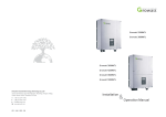
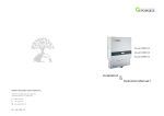
1
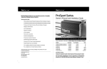
ShineVision
Operation Manual
GROWATT NEW ENERGY CO.,LTD
No.28 Guanghui Road, Longteng Community,
Shiyan, Baoan District, Shenzhen, P.R. China
T
F
E
W
+ 86 755 2747 1900
+ 86 755 2747 2131
service@ginverter.com
www.ginverter.com
GR - UM - 007 - 02
Product Overview 1
Table of Contents
1
Product Overview
2
Basic Operations and Display of Functions
2.1 Check of software version and clear
ShineVision, which consists of a power monitor and a number of transmitters, can
achieve 1 to 6 monitoring modes. The transmitters transmit the power data collected
from a photovoltaic inverter to the monitor and display the data onto the monitor
screen, as along as data of generated energy, the gross generated energy and the
generation income obtained from the above-mentioned data through some simple
calculations. We can also see 3-phase AC voltage, two-way PV voltage, indoor
temperature, date and time, as well as CO2 emissions.
2.2 Code-matching operation
2.3 Basic Setting
Overview
2.3.1 Currency symbol setting
2.3.2 Income coefficient setting
2.3.3 CO2 coefficient setting
2.3.4 Date setting
2.3.5 Time setting
2.3.6 Temperature unit setting
2.3.7 Buzzer setting
2.4 Data storage
2.5 Default interface switching enquiry
2.6 Default interface display
2.7 Reading of Data of Emitter No.1 to 6
3
Contact
Figure 1 Power Monitor and Transmitter
Notes : Power up the monitor via the power adapter, which is delivered in the
package box. But for convenience, sometimes it’s available to use batteries.
1
2
Basic Operations and Display of Functions
2.1 Check of software version and clear
Insert power supply (or batteries) after pressing “up” and “down” keys concurrently,
LCD will display 3 seconds in full screen as shown in Figure 2. The red LED light
flashes quickly twice 3 seconds later (0.5 second per time), then release the “up” and
“down” keys, LED light will be on for a long time, LCD will show the version No. of
the software as shown in Figure 3. LED light will turn off 3 seconds later, and LCD
resets to the default interface as shown in Figure 4. The relevant information has
been cleared.
a
Note: Factory default date: 01/01/2011 (dd/mm/yy), default time: 00:00.
Figure 2
Figure 3
Figure 4
b
2.2 Code-matching operation
Before code-matching operation Please check the RS232 port type,If the RS232 port
of Growatt inverter is compliant with the specification (1) as figure5 (a), please push
the pin1 button up, then plug the transmitter to the inverter via the RS232 and lock
screw as figure5 (b) show.
If the RS232 port of Growatt inverter is compliant with the specification (2) as
figure5 (a), please plug the transmitter to the inverter directly via the RS232 and lock
screw figure5 (b) show. Detailed information refers to the next paragraph.
c
Figure 5 Connect the transmitter to inverter
2
3
After the power is energized, the default interface displays, press “down” and “up”
keys shortly and select the channel No. (optional from channel No.1 to 6), and press
the “down” key for about 3 seconds until the red LED light quickly flash twice , then
release it. After a quite while, simultaneously push aside the black button and then
press the red button on transmitter for a while until the red LED light quickly flash
twice , you will automatically enter the code-matching of the channel as shown in
Figure 6 . Antenna symbol flashes once per second, LCD displays as shown in Figure 7
. After releasing the red button on the transmitter LCD will display as shown in Figure
8. Upon the successful matching of codes, LCD will displays as shown in Figure 8, in
case of code-matching fails in 1 minute, LCD will display the default interface as
Figure 4 .
.
Notes: Antenna symbol is not displayed if codes are not matched, vice versa, display
once the codes are successfully matched.
Figure 9
Figure 10
Note: When pressing ”Ok” after all items are set, the LED light will flash twice to
indicate the setting are verified valid
2.3.1 Currency symbol setting
Press “OK” key to enter the module of currency symbol setting as shown in Figure 10
when the currency symbol flashes. Now symbol
flashes.
Figure 6
Figure 7
Figure 8
2.3 Basic Setting
In the default interface, press “OK” key for quite a while, 3 seconds later, the red LED
flashes quickly twice and then release the key to enter basic setting, LCD displays as
shown in Figure 9, at this time, the currency symbol will flash, switch over among
various function modules through “down” key. Setting should follow the order of
currency symbol (system default as ), income coefficient (system default as 0.163),
emission coefficient (system default as 0.997), date, time, temperature unit (system
default as ℃ ), buzzer switch (system default as
status), press “up” key to
convert the order. Restore to the default interface as shown in Figure 6 if there is no
key operation within 1 minute in the interface of basic settings, or restore as all
options are set.
4
Press “down” key, symbol
flashes, press the “down” key again, $ flashes. Then
press “up” key to convert the order. When a currency symbol flashes, press “OK” key
to select the currency symbol. Then, the currency symbol stops flashing, meanwhile,
you enter the module of income coefficient setting, and “0” in 0.163 flashes.
If setting for currency symbol is not necessarily required, press “down” key to enter
the module of income coefficient setting.
Notes: suppose that $ is selected as the currency symbol, the display of currency
symbol will change to the currency symbol selected at this step.the default currency
symbol of the system is $.
2.3.2 Income coefficient setting
After the currency symbol is selected, press “OK” for a short while to enter the
module of income coefficient setting, as shown in Figure 10. At the time when the
“0” of 0.163 flashes, press “Up” or “Down” to adjust its value, ranging from 0 to 9,
and press “OK” to confirm after adjustment, then the “1” of 0.163 will flash; press
“Up” or “Down” to adjust its value, ranging from 0 to 9, and press “OK” to confirm
5
after adjustment, then the “6” of 0.163 will flash; press “Up” or “Down” to adjust
its value, ranging from 0 to 9, and press “OK” to confirm after adjustment, then the
“3” of 0.163 will flash; press “Up” or “Down” to adjust its value, ranging from 0 to
9, and press “OK” to confirm after adjustment. At the moment, “3” stops flashing
and the interface is restored to the status as shown in Figure 9, then “Kg CO2” starts
to flash.
from 0 to 9, and press “OK” to confirm after adjustment, then the fourth figure “1”
of the Year “2011”
will flash; press “Up” or “Down” to adjust its value,
ranging from 0 to 9, and press “OK” to confirm after adjustment, then the Month
01”
w ill flash; press “Up” or “Down” to adjust its value, ranging from 1
to 12, and press “OK” to confirm after adjustment, then the Day “01”
will flash; press “Up” or “Down” to adjust its value, ranging from 1 to 31, and press
“OK” to confirm after adjustment, then the date will stop flash. Now the interface is
restored to the status as shown in Figure 9 and the time
starts to flash.
If there is no need to set data, press “Down” to enter the time setting module.
2.3.5 Time setting
Figure 11
Figure 12
Figure 13
When the time symbol
flashes, press "OK” for a short while to enter the time
setting module, as shown in Figure 13, then the Hour “00:” of
will flash;
press “Up” or “Down” to adjust its value, ranging from 00 to 23, and press “OK” to
confirm after adjustment, the Minute “:00” of
will flash; press “Up” or
“Down” to adjust its value, ranging from 00 to 59, and press “OK” to confirm after
2.3.3 CO2 coefficient setting
adjustment, then the time stops flashing. Now the interface is restored to the status
as shown in Figure 9 and “Temp.” flashes.
Press “OK” for a short while when Kg CO2 flashes, then you will enter the setting of
CO2 emission factor, as shown in Figure 11. The default value of system is 0.997. At
the time when the first figure “0” flashes, press “Up” or “Down” to adjust its value,
ranging from 0 to 9, and press “OK” to confirm after adjustment, then the first “9”
will flash; press “Up” or “Down” to adjust its value, ranging from 0 to 9, and press
“OK” to confirm after adjustment, then the second “9” will flash; press “Up” or
If there is no need to set time, press “Down” to enter the temperature unit setting
module.
Note: When entering time setting, the block indicates the current system time.
“Down” to adjust its value, ranging from 0 to 9, and press “OK” to confirm after
adjustment, then the figure “7” will flash; press “Up” or “Down” to adjust its value,
ranging from 0 to 9, and press “OK” to confirm after adjustment. Now the interface
is restored to the status as shown in Figure 9 and the date
flashes.
2.3.4 Date setting
6
When the date flashes, press “OK” for a short while to enter the module of date
s
setting, as shown in Figure 12, then the third figure “1” of the Year
“2011”
will flash; press “Up” or “Down” to adjust its value, ranging
Figure 14
Figure 15
Figure 16
7
2.3.6 Temperature unit setting
not be reset until the beginning of the next month or execution of reset. The total
generated energy, total generation revenue and total CO2 emissions are always
stored and will not be reset until data resetting is performed.
When “Temp.” flashes, press “OK” for a short while to enter the temperature unit
setting module, as shown in Figure 14, then ℃ (default system temperature unit)
will flash. Press “Down”, “℉” will flash; press “Up”, “℃” will flash. When the
temperature unit flashes, press “OK” for a short while and confirm the selection of
the current temperature symbol. And now the symbol stops flashing and the
interface is restored to the status as shown in Figure 9, then
flashes.
If there is no need to set temperature unit, press “Down” to enter the buzzer setting
module.
Note: When entering temperature setting, the place showing temperature indicates
Figure 17
Figure 18
Figure 20
Figure 21
the current ambient temperature in the current unit.
Figure 19
2.3.7 Buzzer setting
When
flashes, press “OK” for a short while to enter the buzzer setting
module, as shown in Figure 15. Then
will flash. Press “Up” or “Down” for a
short while, and you can make a shift between
and
. After the status of
the buzzer is set well, press “OK” to confirm and then LCD will return to the default
interface.
Figure 22
If there is no need to set the buzzer, press “Down” and then LCD will return to the
default interface.
2.5 Default interface switching enquiry
Notes: When choosing
and pressing “OK”, the buzzer will be opened and the
sign of ring at the upper right corner of LCD will display, as shown in Figure 16. While
choosing
and pressing “OK”, the buzzer will be closed and the sign of ring
will not display. The system default status of the buzzer is closed.
2.4 Data storage
The generated energy, generation revenue and CO2 emissions on the day are stored
and will not be reset until 0:00 of the next day or execution of reset. The generated
energy, generation revenue and CO2 emissions in the month are also stored and will
8
1) See Figure 8 for default interface.
The first line indicates, in default, the total instantaneous power of each inverter
connected. When the power is not less than 1000W, the unit “kW/W” will be shifted
to kW automatically.
The second line indicates the generated energy, generation revenue and CO2
emissions on the day. The three data are displayed once every 5s in cycle. The
sequence of display in cycle is generated energy, generation revenue and then CO2
emissions, as shown in Figure 17 to 19.
9
There are two modes in the third line, one showing the generated energy, generation
revenue and CO2 emissions in the month and the other showing the total generated
energy, total generation revenue and total CO2 emissions. Two modes are divided
into six interfaces and each interface is displayed after every 5s in cycle, as shown in
Figure 17 to 22. The means of display in cycle is Today-Total-Today-Month. Press
“OK” for a short while in the default interface, you will enter the enquiry of daily,
monthly and total data. When entering the enquiry interface, the historical daily and
total data will be displayed, as shown in Figure 17. Then, press “Down” for a short
while for enquiry of generated energy, generation revenue and CO2 emissions from
Today to Total in sequence, as shown in Figure 17 to 19, and for enquiry of generated
energy, generation revenue and CO2 emissions from Today to Month in sequence, as
shown in Figure 20 to 22. Or press “Up” for a short whole, and you will see the
enquiry results in the opposite direction. The default interface will appear by
pressing “OK” for a short while in any interface of enquiry or when there is no
operation of enquiry at all in 30s.
The fourth line indicates time and temperature.
2) Press "Up" or “Down” for a short while in the default interface (Figure 8), then
you will enter the enquiry of phase voltage and two-circuit PV voltage for threephase AC of each channel, as shown in Figure 23 (showing the enquiry result of CH:
01 channel; the enquiry for other channels are similar to it). After entering such
enquiry, press “OK” for a short while, and then you will enquiry in sequence and in
cycle “Rvolt--- PV1”, “Svolt--- PV2” and “Tvolt--- PV1”, as shown in Figure 23 to 25.
If there is no pressing on any enquiry interface within 30s, the interface will return to
its default status in 30s.
Figure 23
10
Figure 24
Figure 25
2.6 Default interface display
LCD will automatically refresh its display in the default interface.
1.
The first line displays in default the total real-time power of all photovoltaic
inverters.
2.
The second line displays the actual generated energy, generation revenue and
CO2 emissions by all photovoltaic inverters on the day and the three data are
displayed once every 5s and in cycle.
3.
There are two modes in the third line. The first is to show the actual
accumulated generated energy, generation revenue and CO2 emissions by all
photovoltaic inverters in the month, as shown in Figure 20 to 22; the second is
to show the actual accumulated electric energy, generation revenue and CO2
emissions by all photovoltaic inverters. The two modes are divided into six
interfaces and each interface is displayed once every 5s and in cycle, as shown
in Figure 17 to 22. The sequence of cycle is from Total to Month.
4.
The fourth line shows the time and temperature.
Notes: When the monitor receives error information of photovoltaic inverters, the
first line will display “Error” and its relevant wrong code (supposing 000).
Meanwhile, the buzzer will alarm twice every five minutes (if the buzzer is set
opened), as shown in Figure 26 and the LEC lamp will flash once every second. The
display results of the second and third lines must be corresponding to each other. It
means when the second line displays generated energy on the day, the third line must
display the total generated energy or generated energy of the month at the same
time. The data must be displayed correspondingly and in cycle and the means of
display in cycle is Today-Total and Today-Month, as shown in Figure 17 to 22.
Figure 26
11
2.7 Reading of Data of Emitter No.1 to 6
Press “Up” or “Down” for a short while in the default interface, then “CH:01” or
“CH:06” will be displayed in the clock area, the clock symbol
will disappear and
LCD will show the data of the current channel (The following figures show relelevant
display under relevant codes by switching 6 sensor channels in the default interface).
In the default interface, the total data for Channel 1 to 6 are displayed, as shown in
Figure 27. The LCD display is shown as Figure 28 to 30 after entering all channels
(The figures show the data of CH:01 channel; the data of other channels are much
similar and the only difference is that clock areas show relevant channel numbers).
The explanations on LCD display are as follows:
1.
The first line shows the real-time power of photovoltaic inverters for each
channel.
2.
The second line shows phase voltage for three-phase AC of each channel.
3.
4.
The third line shows two-circuit PV voltage for each channel.
The fourth line shows time and real-time temperature under the current
environment.
Figure 30
Contact 3
If you have some requirements or problems concerning ShineVision, please contact
us and provide related information.
Notes: When choosing CH:01 to CH:06, press “OK” for a short while for the enquiry
of “Rvolt--- PV1”, “Svolt--- PV2” and “Tvolt--- PV1” for relevant channel and the
clock area will display relevant channel number.
Figure 27
12
Figure 28
Figure 29
13