1
Project No. 283496
transPLANT
Trans-national Infrastructure for Plant Genomic Science
Instrument: Combination of Collaborative Project and Coordination and Support Action
Thematic Priority: FP7-INFRASTRUCTURES-2011-2
D5.2
Implementation of transPLANT cloud computing environment
Due date of deliverable: 28.2.2014 (M30)
Start date of project:
1.9.2011
Duration: 48 months
Organisation name of lead contractor for this deliverable: BSC
Project co-funded by the European Commission within the Seventh Framework Programme (20112014)
Dissemination Level
PU
Public
X
PP
Restricted to other programme participants (including the Commission Services)
Restricted to a group specified by the consortium (including the Commission
RE
Services)
Confidential, only for members of the consortium (including the Commission
CO
Services)
Implementation of transPLANT cloud computing environment
Table of Contents 1 Executive Summary ___________________________________________________________________________________ 3 2 Introduction ____________________________________________________________________________________________ 3 3 2.1 Motivation and strategy ____________________________________________________________________________ 3 2.2 Background ___________________________________________________________________________________________ 4 Cloud architecture ____________________________________________________________________________________ 5 3.1 4 Software components _______________________________________________________________________________ 6 3.1.1 OpenNebula ____________________________________________________________________________________________________ 6 3.1.2 COMPSs ________________________________________________________________________________________________________ 6 3.1.3 PMES ________________________________________________________________________________________________ 8 3.1.4 Dashboard _________________________________________________________________________________________ 10 Annexes. _________________________________________________________________________________________________________ 11 4.1 PMES Dashboard User Manual ____________________________________________________________________ 11 4.2 Tutorial How-‐to run transPLANT applications ________________________________________________ 19 2
transPLANT deliverable 5.2
1
Executive Summary
This deliverable describes the architecture of the Cloud environment designed and build to offer a platform for
programmatic and interactive access to applications of interest for plant genomics researchers. At the present
time, the platform is completed and functional. A test pre-production installation is available at BSC
(http://transplantdb.bsc.es/pmes), offering an initial set of tools, including gene prediction, sequence
comparison, NGS sequence mapping to reference, and genome assembly. The offer of applications will be
completed during the reminder of transPLANT project, and eventually maintained by the host institutions in
the future.
The main characteristics of the platform are:
1. A virtualization platform, based in OpenNebula, to control the underlying hardware infrastructure.
Applications are run in virtual machines that are instantiated dynamically following the requirements
of the analysis workflow.
2. Workflows are defined by the use of COMPSs programming model. COMPSs is able to discover
implicit parallelism in the pipelines, and hence, execute otherwise serial operations with an optimal
use of a parallel environment. COMPSs workflows can be defined using Java, C++, or Python.
COMPSs has been adapted to control the virtualization layer, making it transparent to the user, and
also allowing to execute the same workflow in a series of environment, from single workstations, to
HPC or grid/cloud facilities.
3. Applications where the use of COMPSs would not be desirable can be also executed in their native
environment, exploiting already existing parallelism if any.
4. Complex applications are stored in the system as a collection of pre-packed virtual machines that
include the application itself and the necessary software environment. Virtual machines developed
here are fully compatible with most common cloud infrastructures.
5. Access to the system is made through the Programing Model Enacting Service (PMES). On one hand,
PMES offers as a Basic Execution Service (BES) web service, accessible through WS clients, and
also through a Java API. On the other hand, a web based tool (The Dashboard) allow for a full control
of the infrastructure. The Dashboard is useful for small analysis and for development.
The rest of the document describes the architecture, and software components used in the project. Also,
manuals about the use of PMES Dashboard and the applications available at the present time are included as
annexes.
2
2.1
Introduction
Motivation and strategy
The extraordinary reduction of the cost of DNA sequencing techniques has led to an explosion of the available
genomics data. In the present days a large number of mid to large size genomics projects have been started
both in the biomedical and the biotechnological fields. The amount of data now available in the genomics
field has raised a new set of challenges that were not previously envisioned. Any large scale project in
genomics now requires a special care in data management. The size of data no longer allows individual
laboratories to keep their own databases and large data management infrastructures should be designed.
Genomics data is normally produced in large scale sequencing centres acting as data providers, together with
large computational facilities performing at the very least, highly demanding operations like mapping to
references genomes, or genome assembly. However, primary analysis is just the initial phase. A large number
of analysis tools should be applied to sequence data to really obtain useful information. The present paradigm
of a large sequencing centre side-to-side with a large computational facility performing as data providers
cannot fulfil the necessary requirements to complete the analysis. Data transmission, however, becomes a
bottleneck due to two main reasons, the size of the data, and also possible privacy requirements. An obvious
strategy to minimize the requirements for data transmission is to move the analysis tools to the same
infrastructure that holds the data. Mapping and assembly algorithms, although in constant revision, are fairly
3
Implementation of transPLANT cloud computing environment
well established. However downstream analysis is made from a large series of tools, stable or under
development, and normally requires a fairly significant amount of expert’s manual operations. Bench tools
like galaxy (http://www.galaxyproject.org) have become very popular as a possible strategy. They do
incorporate a series of analysis tools next to the data and gives the user a significant degree of flexibility in the
analysis. This approach requires however a centralised infrastructure where new tools have to be specifically
installed by the system administration. The significant overhead precludes a flexible enough environment as
what is needed for the constant changing scenario that is genomic analysis. A second approach, chosen for the
transPLANT project, which is becoming also popular, is virtualization. A virtual environment allows a user to
log in a fully personalized environment containing both data and analysis tools. Virtual environments are built
and destroyed dynamically, and hence, allow a very efficient use of the existing hardware infrastructure.
Virtualization allows to install analysis tools in their optimal software environment (operative systems,
software libraries, etc.), thus reducing the installation overhead and avoiding porting issues. Also, virtual
environments are portable, therefore, the same analysis tools can be available at different data providers, and
users do not need to learn specific details with moving to a different facility.
A second requirement for genomics analysis has also been considered here. Most analysis tools are developed
with small to medium sized datasets. In present genomics, the amount of data is leading to use those tools for
amounts of data much larger than those originally considered. For instance, a sequence assembler designed for
animal genomes, can become useless for plant sized genomes. The reason is not a faulty algorithm, but just
the amount of input data that requires unrealistic memory or CPU time requirements. HPC is a clear solution
for the analysis of large problems; however development of specific HPC solutions is usually out of the scope
of bioinformatics developers. Multiscale approaches are possible solutions. Programming models that allow
executing the same algorithm in several architectures, from personal work stations to HPC supercomputers or
to grid based distributed computing, would smooth the impact of data size increase. In this case the
appropriate run-time layer of the programming model is used in every environment, handling scale issues.
The chosen strategy of the transPLANT computational infrastructure is a double offer: on one hand a Platform
as a Service (PaaS) approach including the necessary tools to develop new applications or to adapt existing
ones to the cloud. The platform will be powered by a multiscale programming model (COMPSs), and
hardware resources are to be managed dynamically using a cloud middleware in a way transparent to the user.
From the point of view of final users, the platform will be following an Application as a Service (AaaS)
approach: Analysis tools, including well known bioinformatics tools and also, transPLANT specific tools will
be provided as a collection of virtual machines. Since transPLANT itself does not provide computational
resources, the infrastructure will be provided as a set of installable packages.
2.2
Background
The lower level of the architecture should consist in a cloud middleware, taking care of the management of
hardware resources. A number of computer solutions in the field of cloud infrastructure exist, from European
proposals like the OpenNebula toolkit or the BSC solution in development, EMOTIVE cloud; or other
international proposals like Eucaliptus or commercial solutions like MS Azure. All those frameworks allow a
flexible control of the hardware and the management of the virtualization environment. However, to be able to
offer higher levels of service (PaaS, AaaS) and based in our previous experiences in these middlewares, the
transPLANT cloud infrastructure have been extended further to offer a more comprehensive software stack.
On top of the cloud computing software stack, a programming model is required to offer an easy porting and
development framework of the applications to be installed. BSC’s COMPSs is an innovative programming
framework for distributed computing environments that enables unskilled programmers to develop
applications that can be run in a distributed infrastructure. The COMPSs runtime has the ability of
parallelizing the applications at task level, distributing the execution of parallel tasks in different resources of
the underlying infrastructure. While COMPSs was initially designed to run in grids and clusters, the current
version has already been enabled to run in the cloud and further developments in this direction are ongoing in
the framework of different projects. A COMPSs-enabled version of Hammer has already been used by EBI for
long runs in the MareNostrum supercomputer (using more than 100.000 CPU hours) demonstrating its
suitability (Tejedor, E., Badia R.M., Royo R., Gelpi, J.L. Enabling HMMER for the Grid with COMP
Superscalar. (2010) Proc. Comp. Sci. 1(1), 2629-2638).
4
transPLANT deliverable 5.2
COMPSs has been an ongoing development project at BSC for seven years now. The first implementation was
the evolution of the implementation of an Integrated Toolkit for Grid unaware application in the CoreGRID
Network of Excellence. COMPSs has been evolved since then, adding new functionalities to the programming
model and new features to the runtime. COMPSs development has been performed by BSC teams as part of
final year undergraduate projects, and Master and PhD theses. Also a number of previous projects have
contributed to COMPSs development: The project OPTIMIS added the possibility of orchestrating
webservices as part of a COMPSs application, the publication of a COMPSs application as a service and the
development of a graphical user interface (COMPSs IDE); project VENUS-C contributed to the extension of
COMPSs with regard to interoperability with different Cloud middlewares through the standard OCCI and
also a connector to MS Azure was developed. Additionally, the PMES service was developed in the VENUSC to support MS Azure applications.
In the project transPLANT, the VENUS-C platform has been used as starting point and extended to support
the specific needs of the project applications. A new design of the infrastructure has been performed and a
new graphic interface (Dashboard) to make easier the deployment and execution of project applications has
been developed.
COMPSs is being used in a number of other funded projects: In the Human Brain Project, COMPSs will be
integrated to provide a unified programming interface. The main extension of COMPSs is expected to be in its
Python binding, already available for transPLANT. Other projects like ASCETIC, and Euroserver, focus in
energy efficiency at different levels. New scheduling strategies to take into account these aspects will be
developed. Future development of COMPSs and other components of the software stack will be incorporated
into the transPLANT software stack.
3
Cloud architecture
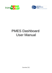
The proposed cloud software stack consists of a local infrastructure managed by a Cloud middleware
(OpenNebula http://www.opennebula.org in this case), where COMP Superscalar (COMPSs
http://www.bsc.es/compss) applications can be executed as well as regular web applications. A diagram of this
architecture is depicted in Figure 1 and a description of each component can be found in the following
sections.
Figure 1. transPLANT cloud infrastructure architecture
The main characteristics of the environment are summarized below:
1. The cloud infrastructure is not ligated to a specific hardware architecture. It can be implemented in any
computer cluster of homogeneous or heterogeneous nature. The minimum composition requires a single
computer node, acting as front-end and managing the cloud. A minimum composition can be used at a
development stage, but a production implementation would require larger clusters. Additional host nodes
5
Implementation of transPLANT cloud computing environment
require only virtualization software compatible with the OpenNebula (KVM, Xen, or VMWare). Computer
nodes should be dedicated, although the resources will be available through OpenNebula.
The present testbed for the infrastructure installed at BSC is in a pre-production structure, including an
externally accessible front-end, and a backend composed by a cluster of 4 x 12-core, 96 Gb RAM, nodes with
access to a several Tb common storage system.
2. The OpenNebula cloud middleware is in charge of managing directly the virtualization environment.
Management is dynamic and can be adjusted to the specific requirements of the applications (when controlled
by COMPSs). OpenNebula can also activate virtual machines in remote providers like Amazon EC2.
Additionally, a series of virtual machines performing housekeeping functions like database provision, or webservice registries, can be instantiated at boot time and maintained permanently in the system.
3. COMPSs programming model is used as workflow manager for applications. COMPSs is able to control
the deployment of virtual machines through OpenNebula. This allows allocating computer resources
according to the needs of the workflow. COMPSs fulfils the multiscale requirement indicated above, the same
workflow definition could be executed in single workstations, in a large HPC facility or in a distributed grid,
without modification. COMPSs runtime is available for computational grids (through GAT connectors: gLite,
Globus, ssh), clusters managed with and without job schedulers (slurm and others), and Clouds (OpenNebula,
EMOTIVE cloud, OpenStack, Amazon EC2, MS Azure). Workflows to be developed in COMPSs can be
expressed in Java, C++ or Python, thus providing coverage for common languages used in bioinformatics.
4. A core manager for the infrastructure (The Programming Model Enacting System, PMES) centralizes user
interaction, application and data management. PMES holds the collection of pre-packed virtual machines
containing the applications, manages input and output of user data, and launches the applications. PMES can
launch COMPSs based applications, but also is able to launch other type of applications. This allows using
applications in their native format, thus minimizing the delay of adding a given functionality to the cloud.
Also the use of the native environment for applications can be desirable when they offer some kind of
parallelization (threads, MPI, etc.)
5. PMES offers programmatic access through SOAP-based web services. To this purpose a Java API
implementation is available, but also well-known WS clients like Taverna (http:// www.taverna.org.uk) can be
used.
6. For occasional or developmental uses, a Web interface (the Dashboard, http://transplantdb.bsc.es/pmes/) is
available. The web interface allows full control of the PMES layer. Users can instantiate and contextualize the
applications, define input and output locations and follow executions. Data transfer is done through the
network or for large datasets from the local storage at the cluster.
3.1
Software components
3.1.1 OpenNebula
OpenNebula is a middleware that enables an easy management of a private Cloud infrastructure. It is
composed by a front-end that offers different interfaces, such as REST, XML-RPC and Web based, and that is
able to manage virtual machines over multiple remote hosts running different hypervisors (e.g. Xen,
http://www.xen.org/; KVM, http://www.linux-kvm.org/page/Main_Page; or VMWare,
http://www.vmware.com/). Moreover, using OpenNebula as infrastructure provider also enables the use of
Amazon EC2 (http://aws.amazon.com/en/ec2/) resources if the local infrastructure is not enough for running a
specific application. Although a fully operational OpenNebula is used, the middleware is hidden from the final
user, as most of its functionality if driven by the PMES.
3.1.2 COMPSs
COMP Superscalar (COMPSs) is a programming model which aims to ease the development of applications
for distributed infrastructures, such as Clusters, Grids and Clouds. COMP superscalar also features a runtime
system that exploits the inherent parallelism of applications at execution time.
For the sake of programming productivity, the COMPSs model has three key characteristics:
6
transPLANT deliverable 5.2
•
•
•
Sequential programming: COMPSs programmers do not need to deal with the typical duties of
parallelization and distribution, such as thread creation and synchronization, data distribution,
messaging or fault tolerance. Instead, the model is based on sequential programming, which makes it
appealing to users that either lack parallel programming expertise or are looking for better
programmability. COMPSs workflows can contain both computation parts and Web Service requests.
Infrastructure unaware: COMPSs offers a model that abstracts the application from the underlying
distributed infrastructure. Hence, COMPSs programs do not include any detail that could tie them to a
particular platform, like deployment or resource management. This makes applications portable
between infrastructures with diverse characteristics. COMPSs run-time takes care of the necessary
adaptation to the underlying infrastructure, in a completely transparent way. The present
implementation of COMPSs, however, allows including specific requirements to guide OpenNebula
in the selection of the necessary virtual machines (See Figure 2)
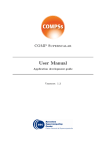
No APIs, standard programming languages: COMPSs control is based on a popular language like
Java, or Python. This facilitates the learning of the model, since programmers can reuse most of their
previous knowledge, and existing script can be easily adapted (Figure 2).
Figure 2. COMPSs language bindings. Examples of COMPSs tasks definition in Java and Python.
7
Implementation of transPLANT cloud computing environment
Application life cycle: When a request arrives to the system, COMPSs' runtime asks for resources (virtual
machines) to the underlying infrastructure and distributes the computational work and Web Service calls of
the application amongst them ensuring that data dependencies are maintained.
COMPSs does that by following a master-worker architecture where the master launches tasks in the available
resources, transmitting them the input files they may need and collecting the results afterwards. Since the
input and output data of each task is specified in the source code of the application by using annotations, the
runtime is aware of the precise moment the dependencies of a task are satisfied and thus it can be executed. It
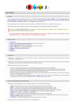
is worth to mention that the definition of tasks can include a specification of the needs of each task in terms of
resources, and that COMPSs will create or destroy virtual machines as the computational load grows or
decreases (Figure 3).
Figure 3. OpenNebula console showing the evolution of VM management.
3.1.3 PMES
The PMES component is an implementation of a Basic Execution Service
(http://www.ogf.org/documents/GFD.108.pdf), which has been designed to submit job execution requests to
remote servers. It takes a Job Submission Description Language (JSDL)
(http://www.gridforum.org/documents/GFD.56.pdf) document describing, amongst other information, an
application's name and its input parameters, and starts the COMPSs' runtime (master) in order to execute it.
The runtime is also started in a virtual machine, so the PMES needs to be able to interact with OpenNebula as
well.
The PMES enables the execution in the virtualized resources of two different kinds of applications: COMPSs
and, stand-alone applications. This functionality covers the use of pre-existing applications or workflows,
which can be run on the cloud platform without modification. Although the use of COMPSs as workflow
manager is expected to improve the performance on workflow executions, especially in an HPC environment,
the necessary modifications required to adapt software can unnecessarily delay their implementation.
Allowing a direct execution is expected to increase the short-term usability of the system. COMPSs based
applications are executed by launching the COMPSs runtime in a virtual machine; whereas to execute
standalone applications, the PMES is also able to run any specific command with certain inputs, either directly
(for low demanding applications) or launching the necessary, possibly pre-installed, VM’s.
8
transPLANT deliverable 5.2
3.1.3.1 Programmatic access
The Basic Execution Service (BES) it is an Open Grid Forum (OGF) standard specification for a SOAP
service to which clients can send requests to initiate, monitor, and manage computational activities. The basic
operations provided are 1. Create activity, 2. Terminate activities, 3. Get activity statuses, and 4. Get activity
documents. Jobs are described using Job Submission Description Language (another OGF standard
compatible with BES, see Figure 4 for an example of JSDL). Some job characteristics that can be specified
are: Application name, Executable & arguments, Hardware requirements (CPU, memory, storage…), CPU
time, or Data staging.
PMES implements a SOAP based web service implementing BES. Web-service can be accessed using wellknown clients as Taverna (Figure 5). For more intensive use, a Java API is available to generate the
appropriate job definitions and launch executions (see Figure 6 for an example code using the API). The use
of the API allows to fully integrate calls to transPLANT cloud infrastructure as modules in more complex
applications.
Figure 4. Example of JSDL specification as generated by the API.
Figure 5. PMES programmatic access. Example of Workflow created within Taverna
9
Implementation of transPLANT cloud computing environment
Figure 6. PMES programmatic access. Java code example enacting a BWA-based pipeline
3.1.4 Dashboard
Although the infrastructure is meant to be used mainly with programmatic tools, a graphic web interface has
been developed to facilitate the user interaction with the platform (Figure 7). The dashboard is useful for
simple executions or developing purposes. A more detailed explanation of the Dashboard and the procedure to
launch applications through this tool can be found in the Annexes to this document.
Figure 7. Screenshot of PMES Dashboard
10
transPLANT deliverable 5.2
4
4.1
Annexes.
PMES Dashboard User Manual
Basic guide to use the PMES Dashboard. The document is maintained at
https://transplantdb.bsc.es/documents/man/PMES_Dashboard_Manual.pdf.
11
PMES Dashboard
User Manual
https://transplantdb.bsc.es/documents/man/PMES_Dashboard_Manual.pdf
Last revision: December 2013
Implementation of transPLANT cloud computing environment
Introduction
This document describes the different functionalities of the PMES Dashboard. Principally, the dashboard
enables the management of applications, jobs, storage and users in the PMES. An application defines a piece
of software that can be run in the underlying infrastructure, a job is an execution of that piece of software,
and a storage defines a remote storage (e.g. FTP server) that jobs can use to retrieve input data and upload
results.
The typical usage workflow of the dashboard will consist in the following three steps:
•
•
•
Add a remote storage
Create an application
Run a job
These three steps are described in detail in the following sections.
5
Storage Management
To enable jobs to retrieve input data and upload output data to a remote location, the first step is to define a
storage. For that means, in the main view of the dashboard, go to Edit → Storage, as shown in Figure 1.
This will open a new window listing the current available storages. To add a new one, type a valid URL (e.g.
ftp://bscgrid20.bsc.es) in the upper text box and hit the green button in its right ( ). The credentials to access
the storage will be requested when needed. To remove an existing storage from the list, hit the red button in
its right ( ).
Figure 1 - Main view of the dashboard
14
transPLANT deliverable 5.2
6
Applications Management
The PMES enables the execution of two kinds of applications: COMPSs1 and non-COMPSs. On one hand, a
COMPSs application defines an application written and compiled using COMPSs programming model,
usually packaged in a JAR file, which will be executed in parallel using COMPSs runtime. On the other
hand, a non-COMPSs application just defines the execution of a command in a virtual machine (e.g. blastall).
To manage the applications, go to Edit→ Applications in the main view of the dashboard (shown in Figure
1). This will open a new window listing all the available ones. To create a new one, hit the green button ( )
on the upper right corner of the list. This will open an additional window for the introduction of the
application's characteristics. This last dialog is depicted in Figure 2.
Figure 2 - Create a new application
The information to be provided to create a new application is the following:
•
Name: The name of the application.
•
Image: The name of the image that has to be used to create virtual machines when executing the
application. If the infrastructure provider does not inform about the available images, this value will
have to be entered manually.
•
Location and Path (Optional): Only if the application consists of a package that has to be deployed
in the virtual machines before its execution (useful for COMPSs applications). Location specifies the
URL of the remote storage where the package resides, and Path the relative path to the package in
that
storage.
For
example:
Location
=
ftp://bscgrid20.bsc.es
and
Path
=
/app_repository/gene_detection.tar.gz
will
deploy
package
in
ftp://bscgrid20.bsc.es/app_repository/gene_detection.tar.gz after the virtual machines are created.
•
Executable: Name of the executable to run. In COMPSs applications, name of the main class (e.g.
simple.Simple), in non-COMPSs applications, name of the command (e.g. /usr/bin/maker).
1 http: //www.bsc.es/compss
15
Implementation of transPLANT cloud computing environment
•
COMPSs: If it is a COMPSs application or not.
•
Public: If the application can be executed by other users.
•
Description (Optional): A brief description of the application.
•
Wall Clock Time (Optional): The default execution time of the application.
•
Disk Size (Optional): The default disk size for the virtual machines when running the application.
•
Cores (Optional): The default number of cores for the virtual machines when running the
application.
•
Memory (Optional): The default memory for the virtual machines when running the application.
•
Max VMs (Optional): The maximum number of virtual machines to run the application. This is
used only for COMPSs applications.
•
Min VMs (Optional): The minimum number of virtual machines to run the application. This is used
only for COMPSs applications.
Besides that information, each application also contains a list of arguments. To add a new one, hit the green
button on top of the argument list ( ). Each argument will be optional if specified or mandatory otherwise,
and it is defined by a name, an optional default value and an optional prefix. When launching the application,
a value for each argument will be requested and passed to the command line in the order they appear on the
list. The way the actual command will be constructed is:
•
•
For COMPSs applications: runcompss executable [[prefix] [argument]]...
For non-COMPSs applications: executable [[prefix] [argument]]...
Once all the information is provided, hitting the Save button will add a new application to the system.
Finally, applications can be edited by hitting the pencil button ( ) on their right in the applications list.
Job Management
Once an application has been created, it is possible to run jobs in the infrastructure. To do that, in the main
view of the dashboard (Figure 1), go to Jobs→ New and select the type of job. This action will show a job
submission dialog like the one depicted in Figure 3. To create a new job, select the application to launch,
insert the desired value for each argument, specify the necessary resources in the Advanced tab (if no defaults
have been defined for the application) and hit the Submit button
16
transPLANT deliverable 5.2
Figure 3 - Job submission dialog
In the case the input data of the job is located in an external location, the tab Input Files permits the
definition of stage-ins, i.e. files or directories that need to be fetched before running the application. Figure 4
shows an example of two input files. In this case both are directories (represented by a “/” character at the
end of their name). PMES will copy the directory ftp://bscgrid20.bsc.es/data as a 'data' directory in the virtual
machine running the job (and the same for the 1B6C directory). On the other hand, if some results need to be
transferred to an external location after the job execution, the Output Files tab permits the definition of what
is known as stage-outs. Figure 5 depicts an example in which, after running the application, the directory
'scores' will be copied to ftp://bscgrid20.bsc.es/results (the “/” character at the end of the file name indicates
that it is a directory). In the case of stage-outs, the Update check-box indicates whether the file has to be
transferred periodically during the execution or just at the end of it. As usual, to add stage-ins or stage-outs
hit the green button on top of their list ( .
Figure 4 - Input Files
17
Implementation of transPLANT cloud computing environment
Figure 5 – Output files
Finally, in the tab Logs a remote directory can be specified to upload the different logs that the job generates.
A remote storage has to be selected and then a path ending in “/” (to denote it as a directory) specified. Logs
will be uploaded periodically, keeping their contents updated as the execution goes on.
Once the Submit button is hit, the new job will appear in the main view of the dashboard, as depicted in
Figure 6. When selecting a job in the job list, its details and logs will be displayed in the panel below. Hitting
the red button ( ) on the right of each running job will cancel it, and hitting the blue arrows ( ) on the right
of each finished job will open a dialog to submit a new job with the same settings as the selected one.
Figure 6 - Job details
7
User Management (admin)
Only the admin user can add and remove other users. To do that, go to Edit→ Users in the main view of the
dashboard.
8
Contextualization
It is possible to specify contextualization variables as key-value pairs that are passed to the infrastructure
provider when creating new virtual machines. To do that, go to {username} → Settings in the main view of
the dashboard, and the to the Contextualization tab
.
18
transPLANT deliverable 5.2
8.1
Tutorial How-to run transPLANT applications
Detailed guide to run both stand-alone and COMPSs applications through the PMES Dashboard,
including references to the applications available. This document will be updated with the new
applications included in the platform.
The document is maintained at
https://transplantdb.bsc.es/documents/man/guide_to_run_TransPLANT_applications.pdf
19
Guide to run transPLANT
applications
User support: transplant@bsc.es
https://transplantdb.bsc.es/documents/man/guide_to_run_TransPLANT_applications.pdf
Revised. January 2014
Implementation of transPLANT cloud computing environment
Introduction TransPLANT cloud computing environment is made accessible over the internet through the PMES
dashboard. PMES[1] (Programming Model Enacting Service) is used as the entry point to the transPLANT
local infrastructure and operates OpenNebula[2], the middle-ware responsible of the virtual machines
management where TransPLANT applications are executed.
Figure 1 transPLANT cloud general architecture PMES dashboard handily enables the user to create, submit and monitorize job requests invoking either standalone or COMPSs[3] applications. Such applications are merely the piece of code to be executed in the cloud
infrastructure, and they can correspond to bare executable and web service wrappers, or to more complex
pipelines. In any case, the distributed computational power is exploited, being the parallelism built-in in
straightforward applications, or being featured or enhanced through COMPS superscalar, a programming
model that pushes the task items to the available nodes in an orchestrated fashion.
In a more advanced mode, PMES dashboard also permits to create and configure a new application, yet a
virtual machine image containing the application code needs to be manually uploaded to OpenNebula.
TransPLANT users do not require to create new applications, since they already have an available collection
of pilot applications - described below. More information regarding the introduction of new applications can
be found in the PMES dashboard manual[4].
Hence, the essential steps to be followed by a user are resumed here:
Upload input data
to a remote storage
data management
Define the
remote storage
Create, run & monitorize
the job
PMES dashboard execution
Download output data
from the remote
storage
data management
The present document describes the two essential parts a user deals with when running an application using
PMES: the data management and the application execution itself. Besides, the list of currently available
transPLANT applications is also detailed.
Data management: Input/Output storage
The cloud infrastructure needs to gain access to the user input data, just like the user will require access to the
output data. In order to make such input/output operations possible, a remote storage must be defined,
specifically an FTP site. Its URL and credentials are petitioned by the PMES dashboard and the data is
transparently transferred.
22
transPLANT deliverable 5.2
Figure 2 : General architecture with the I/O storage However, some input data might be frequently used and could reach a considerable size, for instance,
resources like databases or libraries. For such cases, BSC has made available a data storage system called
DATA2 which is accessible from the cloud and required by some transPLANT applications. In order to use
this storage, users need to configure PMES by setting the following environment variables in
username→settings→contextualization:
•
DATA2_USER = guest
•
DATA2_PWD = guestTransplant01
These variables are used to mount the mentioned storage during the boot process of the virtual machines.
Application execution (use case: MAKER)
The present section numerates the steps to follow in order to run a transPLANT application via the PMES
dashboard. To get a comprehensive and detailed description of the totality of the Dashboard features, consult
the PMES Dashboard manual document.
Configuring PMES
The first thing to do is to log in https://transplantdb.bsc.es/pmes and get familiar with the new interface. User
accounts can be obtained from transplant@bsc.es. The Dashboard is conceived as a portal to a remote and a
distributed computational infrastructure like the transPLANT cloud. Hence, the central panel is occupied by
the current state of the user's jobs. Jobs can be monitored, debugged and edited, but first of all, the user should
create and submit them.
In order to create a job request, PMES needs to be configured so that the framework will know from/to where
the I/O data should to be transferred, as well as which are the specific environment variables to be set (if any).
These arrangements are stored in the application, thus they only are required to be configured once.
23
Implementation of transPLANT cloud computing environment
Storage
The storage where input and output data is located should be defined in edit→storage, on the top-left corner.
Here the user will have a list of FTP sites to which the virtual machines will have access. Type in the URL
from where you will upload the input data in the form: ftp://myFTPsite/myFolder/ (notice the final slash).
Later on, when attempting to connect to the storage, the application will petition your FTP site credentials.
Contextualization
Virtual machines in which the applications run may need the setting of particular environment variables to
perform special functions. This is the case for mounting the previously mentioned DATA2 local storage. To
allow jobs to access to such device, go to username→settings→ contextualization and define the two variables
as described in the previous section “”.
Creating a job request
Here we are going to detail how to run MAKER application, a stand-alone job. In order to create a new job,
we go to Jobs→new→single Job. If the application was prepared to be executed using COMPSs, we would
select Jobs→new→COMPSs job. The appearing window allows the user to choose the application we want to
run, configure all its parameters and define from where the inputs should be retrieved and where the final
output should be transferred to.
By choosing “maker” in the Application selector, its how-to description appears on the top-right corner frame
(fig. 3). The text offers a short description of what the application does and details each of the arguments and
the expected outputs.
Figure 3: New job window On the second half of the windows, four tabs indicate the four sequential pieces of information to fill in before
submitting a job:
24
transPLANT deliverable 5.2
Arguments:
By completing the application arguments, the user is in fact building up the command line that will be later
executed in the virtual machine. Some options may have already a default value, modify it as desired.
MAKER application takes only four arguments which for this tutorial we will set as shown in figure 3.
Two of the arguments are files. In fact, they are configuration files containing, among other parameters, the
path to other files required by the MAKER executable. This is precisely the data the user needs to upload to an
FTP site to make it accessible to the virtual machines. It is done in the Input files tab.
Input files:
In this tab, the user indicates which is the data that PMES should transfer to the cloud infrastructure. The three
columns correspond to: (1) the user FTP site where the data is located, (2) the user FTP file or directory to be
securely transferred and (3) the destination file or directory of the virtual machine where the data is to be
transferred.
A pair of sample MAKER configuration files and the rest of the required files to test MAKER can be found in
two different locations. The first is the DATA2 storage in the following directory:
/data2/INB/transplant/maker. The second location is : https://transplantdb.bsc.es/documents/samples/use the
DATA2 sample inputs, there is no need to upload any input file to any FTP site, as PMES has access to
DATA2 storage (read section ). Hence, no further work has to be done in this “Input files” tab. Nevertheless,
the user should come back to the “Arguments” tab, and modify it accordingly.
Figure 4: Argument tabs. Inputs files do not need to be uploaded if they are already accessible to PMES, for
instance, through the DATA2 storage. Then, the arguments that are files, need to include the total path to
indicate PMES where exactly the input files are located.
On the contrary, to use the sample data located at the transPLANT site, the user should download it and make
it available to PMES via the FTP site specified when configuring PMES (ftp://myFTPsite/myFolder/).
There are different ways to fill in input files form, but in any case, the destination file must correspond to the
file name as specified in the arguments section. Figure 5 shows several combinations that eventually upload
the same files and match up with the arguments as previous reported:
25
Implementation of transPLANT cloud computing environment
Figure 5. Input files tab. Three different ways to upload the inputs files to the working directory of the virtual
machines. (A) Specifying the files one by one. (B) Indicating PMES to transfer a whole directory by
terminating the path with a slash. The source path “./” refers to the directory under the storage path. The
target path “.” refers to the working directory of the virtual machine. (C) Again, we transfer a whole
directory, this time “myFolder”, the directory under the storage path.
Again, bear in mind that changes in the target path, need to be reflected in the arguments tab:
ftp://myFTPsite/
myFolder/
myRemoteFolder/
Figure 4: The remote target path needs to correspond with the file name specified in the arguments tab Output files:
In this tab we indicate the file or directory to upload the results back to the user FTP site once the application
finished. Following the input files tab philosophy, the three columns correspond to: (1) the user FTP site
where the output is to be transferred, (2) the location of the output in the virtual machine, and (3) the user FTP
site destination file or directory. The name of outputs generated by the application and required to complete
the source path, are usually specified in the text describing the application.
In our sample case, and according to the basename argument filled in the first tab, the form looks like follows:
26
transPLANT deliverable 5.2
Figure 5: Output files tab. Logs:
PMES dashboard returns a series of log files and in this tab, the user is asked where upload them. They are
periodically updated as the job execution goes. In our case, we copy them in the same FTP folder than the
output files:
Figure 6:Logs tab . Reached this point, we are ready to simply send the job to the cloud infrastructure by pressing the “submit”
button.
However, we also can modify some execution parameters through the Advanced tab, on the top-left corner of
the “new job” window. The user can decide whether to reduce or increase the number of CPU’s of the job, for
instance. Changes in this section may need adjustments of some arguments and the user should be aware of
this. In our case, the CPU’s job needs to match with the argument cpus blast, because our MAKER
application is not using MPI, thus BLAST2 is the program within the pipeline consuming more resources.
Monitoring and debugging the job
Once
the
job
is
submitted,
it
appears
in
the
central
panel,
together
with
its
state
(PENDING/FINISHED/FAILED). Selecting a job, the user obtains more information. The icon
displays the states of the different virtual machines that compose that job. The icon
allows editing the job
and launch it again, if needed. In the lower panel, the three types of job logs are presented: Manager.log (the
OpenNebula logfile), Stdout.log (the application standard output) and Stderr.log (the application standard
error). All of them are periodically uploaded to the FTP site, as defined while setting the job.
When the job successfully finishes, the output files are uploaded to the FTP site, as the user defined in the
output files tab.
27
Implementation of transPLANT cloud computing environment
Application repository (February 2014)
GENE DETECTION
Application Type
COMPSs
This application is a pipeline that detects genes in a genome using a reference protein from a closely
related species using Genewise. It makes the process more efficient by restricting the Genewise
executions to the most relevant regions with the help of Blast and Blast2Gene.
- Genewise: tool that compares a protein sequence to a genomic DNA sequence, allowing for introns and
frameshift errors. (PMID: 10779496)
- Blast: The Basic Local alignment tool that finds regions of local similarity between sequences.
- Blast2gene: program that allows a detailed analysis of genomic regions containing completely or
partially duplicated genes.
Genome file A genome multifasta file
Arguments
Proteins file Collection of related protein sequences (fasta).
Results
directory
Destination of results
Input Files
Both, the genome and the collection of proteins
Output Files
Name of the results directory
Sample Files
Special requirements
28
transPLANT deliverable 5.2
BLAST
Application Type
COMPSs
This application is a wrapper of the widely used local alignment tool BLAST. The application allows the
user to compose the complete command line. Input query sequences are splited in number of subqueries.
- BLAST: program that compares nucleotide or protein sequences to sequence databases and calculates
the statistical significance of matches.
blast binary
Path to the Blast binary. Default: /binary/blastall
query
sequence
Input sequence filename (fasta/multifasta).
database
Path to the database.
Default: /data2/INB/ddbb/NCBI/bin/blast/[DB_type].
Available DB_types are:
- all_contig: Homo sapiens build 37.3 genome
- env_nt: environmental samples
- est_human: GenBank Human EST entries
- est_mouse: GenBank Mouse EST entries
- est: GenBank+EMBL+DDBJ sequences from EST
Divisions
- est_others: GenBank non-mouse and non-human EST
entries
- htgs: Unfinished High Throughput Genomic Sequences
- human_genomic: NCBI genome chromosomes - human
- nt: Nucleotide collection (nt)
- other_genomic: NCBI genome chromosomes - other
- patnt: Nucleotide sequences from the Patent division
- pdbnt: PDB nucleotide database
- refseq_genomic: NCBI Genomic Reference Sequences
- refseq_rna: NCBI Transcript Reference Sequences
- env_nr: Proteins from WGS metagenomic projects
- nr: non-redundant GenBank CDS translations +PDB
+SwissProt +PIR +PRF
- pataa: Protein sequences from the Patent division
- pdbaa: PDB protein database
- refseq_protein: NCBI Protein Reference Sequences
- swissprot: Non-redundant UniProtKB/SwissProt
fragment
number
Number of fragments of the input sequence to use
command
line args
Command line arguments for blast. Example: “-n blastp”.
Options: http://www.ncbi.nlm.nih.gov/staff/tao/URLAPI/blastall/
temporary
directory
Path to the machine temporary directory. Default: /tmp
output file
Filename containing the results of the application
debug
Activates the debug mode of the application (optional).
Arguments
Input Files
The query sequence file.
Output Files
The file named as defined in the argument “Output file”
Sample Files
Special requirements
The application requires access to the DATA2 data storage, where all databases
are stored.
29
Implementation of transPLANT cloud computing environment
MAKER
Application Type
stand alone
This application is a wrapper for the genome annotation pipeline MAKER 2.
- MAKER identifies repeats, aligns ESTs and proteins to a genome, produces ab initio gene predictions
and automatically synthesizes these data into gene annotations.
Arguments
configuration
file Opts
Maker configuration file detailing general options and input files
configuration
file Bopts
Maker configuration file detailing the similarity parameters
cpus blast
Number of CPUs of BLAST2. They should correspond to the
total number of CPUs reserved.
basename
Base-name of the pipeline output
Input Files
The two configuration files need to be uploaded, together with any other file
referenced into such control files.
Output Files
The application returns a compressed folder called [BASENAME].tar.gz
Sample Files
Configuration files:
https://transplantdb.bsc.es/documents/samples/maker/maker_opts.ctl
https://transplantdb.bsc.es/documents/samples/maker/maker_bopts.ctl
Files referred into the configuration file Opts:
https://transplantdb.bsc.es/documents/samples/maker/dpp_contig.fasta
https://transplantdb.bsc.es/documents/samples/maker/dpp_est.fasta
Special requirements
30
transPLANT deliverable 5.2
AbySS
Application Type
Arguments
This application runs ABySS. The parallel version is implemented using MPI and
it is capable of assembling large genomes.
- ABySS is a de novo, parallel, paired-end sequence assembler, designed for short
reads. The single-processor version is useful for assembling genomes up to 100
Mbases in size.
kmer size
k-mer size to test. Format: k=integer.
number of
threads
Number of threads used in the execution. Format: j=integer.
name
A name to identify the execution (e.g., name of the specie).
Format: name=string
pair-end
libraries
A name to identify the paired-end library.
By default: lib='pe1'
mate-pair
libraries
A name to identify the mate-pair libraries.
By default: mp='mp1'
pe library files
The name of the files with the paired-end reads.
Format: pe1='string1 string2'
mp library files
The name of the files with the mate-pair reads.
Format: mp1='string1 string2'
output directory Name of the directory for the results. [BASENAME]
Input Files
The fastq files required to run the application corresponding to the arguments “pe
library files” and “mp_library files”.
Output Files
The application returns a folder called [BASENAME].tar.gz
Sample Files
As an example, you can run the assembly of staphylococcus_aureus with the data
from the GAGE project:
The libraries are in: http://gage.cbcb.umd.edu/data/index.html
Special requirements
31
Implementation of transPLANT cloud computing environment
BWA
Application Type
Stand-alone
This application is a sequential pipeline that uses BWA to align paired-end reads against a reference
genome and converts the resulting alignment into a BAM file using SAM Tools.
- BWA (Burrows-Wheeler Alignment) is a software package for mapping low-divergent sequences
against a large reference genome.
- SAM Tools provide various utilities for manipulating alignments in the SAM format, including sorting,
merging, indexing and generating alignments in a per-position format.
fastq1
paired-end reads file 1 in fastq format.
fastq2
paired-end reads file 2 in fastq format.
indexed reference genome (Ensembl release 20). Options:
Arguments
Reference
Genome
Output
basename
arabidopsis_lyrata
arabidopsis_thaliana
brachypodium_distachyon
brassica_rapa
chlamydomonas_reinhardtii
cyanidioschyzon_merolae
glycine_max
hordeum_vulgare
medicago_truncatula
musa_acuminata
oryza_brachyantha
oryza_glaberrima
oryza_indica
oryza_sativa
physcomitrella_patens
populus_trichocarpa
selaginella_moellendorffii
setaria_italica
solanum_lycopersicum
solanum_tuberosum
sorghum_bicolor
triticum_aestivum
triticum_urartu
vitis_vinifera
zea_mays
Base-name of the pipeline output
Input Files
The files required to run the application correspond to the arguments fastq1 and
fastq2.
Output Files
The pipeline generates an output file called [BASENAME].bam
Sample Files
Fastq1: https://transplantdb.bsc.es/documents/samples/bwa/1.fastq.gz
Fastq2: https://transplantdb.bsc.es/documents/samples/bwa/2.fastq.gz
Reference Genome: arabidopsis_thaliana
Output base-name: results
Special requirements
The application requires access to the DATA2 data storage, where Reference
genomes are is stored
32
transPLANT deliverable 5.2
References
[1] Programming Model Enactment Service – http://venus-c.sourceforge.net/
[2] OpenNebula – http://www.opennebula.org/
[3] COMP Superscalar – http://sourceforge.net/projects/compss/
[4] PMES dashboard manual: https://transplantdb.bsc.es/documents/man/PMES_Dashboard_Manual.pdf
33