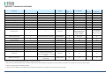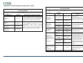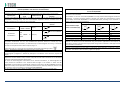
1
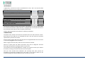
USER MANUAL MNPG112 Rev.0- 10-05-2013 INDEX TECHNICAL PROBLEMS ........................................................................................ 16 INFORMATION ON THE MANUAL .......................................................................... 1 WRITING CONVENTIONS ............................................................................................ 1 ELECTROMAGNETIC INTERFENCES ....................................................................... 16 WARRANTY .......................................................................................................... 2 TECHNICAL FEATURES ......................................................................................... 18 NOTES .................................................................................................................. 2 APPENDICES ....................................................................................................... 19 Appendix A – ENVIROMENTAL PROTECTION ........................................................... 19 Appendix B – LABELS ................................................................................................ 19 Appendix C – THERAPEUTIC TREATMENT ................................................................ 20 Appendix E – ELECTRO-MAGNETIC COMPATIBILITY TABLES ................................... 21 CAUTIONS ............................................................................................................ 2 ! WARNINGS !....................................................................................................... 3 INTRODUCTION TO THE TECNOLOGY ..................................................................... 4 Techniques of application .......................................................................................... 5 How it works ............................................................................................................... 5 IN GENERAL .......................................................................................................... 5 INTENDED USE...................................................................................................... 6 INDICATIONS............................................................................................................... 6 CONTRA-INDICATIONS................................................................................................ 6 PRELIMINARY NOTES ............................................................................................ 6 UNPACKING ................................................................................................................ 6 SETTINGS UP ............................................................................................................... 7 ACCESSORIES .............................................................................................................. 8 CONNECTIONS ............................................................................................................ 8 DEVICE DESCRIPTION ............................................................................................ 9 HOW TO USE OF THE DEVICE ................................................................................11 BEST USE ................................................................................................................... 11 SETTINGS.............................................................................................................11 VARIOUS ................................................................................................................... 12 LANGUAGE................................................................................................................ 13 DEFAULT ................................................................................................................... 13 FREE PROCEDURE ................................................................................................13 LOADING PROGRAMS ..........................................................................................14 CREATE PROGRAMS .............................................................................................14 MAINTENANCE ....................................................................................................15 TROUBLESHOOTING CHART................................................................................. 17 products or manuals. The company will not assume any responsibility for any major cases: INFORMATION ON THE MANUAL This manual is addressed to: - improper use of the machine; - user of the machine; - use against to specific national regulations; - owner; - incorrect installation; - responsible; - defects in power; -people in charge of moving; - serious shortcomings in maintenance; - installers; - changes and unauthorized interventions; - users; - use of parts or materials not specific to the model; - people in charge of maintenance. - total or partial non-observance of the instructions; This document provides valuable information regarding the installation, set up and use of I-TECH.AR. - exceptional events. It is a useful and essential reference guide for the user: read the contents of the manual carefully before installing the equipment and keep it on hand at all times for future reference. N.B. The Therapy Application Manual is available upon request. It is of vital importance that you strictly adhere to the recommendations contained within the manual in order to avoid malfunction, which may cause damage to the equipment and consequent annulment of the validity of the warranty. Certain sections of the manual have been underlined in order to highlight their importance. Furthermore, in order to obtain the highly efficient technical service available from the manufacturer, it is essential that any handling of the equipment be in accordance with the instructions provided. The limits of this manual are: - the user manual cannot replace proper experience; - the instruction manual, for particularly difficult operations, can only be a reminder of the main operations. Please contact the manufacturer to get further information. WRITING CONVENTIONS NOTE These contain important information and useful tips for operating the equipment. CAUTIONS The CAUTION message appears before operations, which, if not correctly performed, may cause damage to the machine and/or its accessories. ! WARNING ! This signals operations or situations, which, if unknown to the operator, or incorrectly carried out, may harm the operator. The manual is to be considered part of the equipment and must be preserved for future reference until the decommissioning of equipment. The operating instructions must be available for consultation in the vicinity of the machine and properly stored. This manual reflects the state of the art at the time of sale and cannot be considered inadequate because later updated based on new information. The manufacturer has the right to update products and manuals without necessarily updating preceding I.A.C.E.R. Srl 1 2. WARRANTY I.A.C.E.R. guarantees the quality of its products for a period of 24 months from the date of purchase, when information contained in this manual regarding installation, use and maintenance is strictly adhered to. The guarantee covers the replacement of faulty parts. The warranty does not however, include the replacement of the equipment. carefully clean and disinfect all parts of the machine and accessories which have been in contact with patients; Any equipment which the technical department does not consider hygienic (Italian law T.U.S. 81/2008 on safety in the workplace) will not be accepted; 3. disassemble accessories and any mechanical supports; 4. use original box and packing materials; 5. enclose Service Request Form (available from the manufacturer) on which to write detailed informations regarding the nature of the problem in order to facilitate the technical department’s intervention and save time on repair. The warranty does not cover any malfunction or damage caused by: ù - incorrect connection and installation; NOTES - incorrect use due to non-compliance with instructions contained in this manual; - improper or inadequate maintenance; - use of the machine in environmental conditions which do not conform with those specified for the product; - unauthorised opening of the outer casing; - tampering or unauthorised modifications; - use of non-original accessories. The warranty is supplied free port I.A.C.E.R. Srl. Should you need to return the goods then please note the packing instructions as follows. Enclose a copy of the purchasing receipt. PRELIMINARY NOTES − The installation of the device does not require any special care, is therefore simple and immediate. USE − Each time you click the START button or the STOP button the machine will emit a long confirmation beep. − Each time you select the SMART-CARD will take a few seconds to allow the machine to recognize and load the card: meanwhile it shows the message PLEASE WAIT. − The selection of the SMART-CARD is possible only if previously inserted into the slot. − To prevent erasure or formatting of SMART CARD, confirmation is required. MAINTENANCE − For an optimal use of the device and to guarantee its maximum performance, it is recommended to perform maintenance at the correct time and suggested ways. You should insure the postal package. CAUTIONS Before sending the machine back for suspected malfunction, we recommend that first you carefully consult sections regarding MAINTENANCE and TROUBLESHOOTING of the manual, as a large part of the problems and faults are usually due to inadequate maintenance or small technical problems which can often be easily solved by the user himself. A simple call to the I.A.C.E.R. Srl technical department may prove to be the solution to the problem. When re-packing the equipment for return to the manufacturer, proceed as follows: PRELIMINARY NOTES - The customer is liable for all damage caused by inadequate packaging of the material. Keep the original packaging of the unit: it will be needed if the unit is returned to the company. - Do not use the equipment in places where it might get wet . - Before operating the machine carefully check the correctness of the connections according to the instructions. - Do not use accessories other than the ones provided: they might damage the unit, causing the warranty to become void. In case you have any problems or difficulties with installation, contact I.A.C.E.R. Srl technical support. 1. unplug the machine and any connections, devices, applicators etc; - I.A.C.E.R. Srl If using the same extension for the unit and other units, make sure that the total current being absorbed by the connected units, does not exceed the max current allowed for that type of cable and that, however, it does not exceed 15 A. 2 - The therapeutic suggestions are stored in the permanent memory of the machine. These protocols can be edited but not possible to save any changes. - The protocols of therapeutic suggestion preloaded on the machine cannot be deleted. - - It is not possible to define a number of sessions suggested to evaluate the effectiveness of the treatment, since they are related to the power delivered to the patient undergoing treatment. E 'task of the physician to decide the number of therapy sessions which subject the patient according to the specific requirements of the case, in order to ensure to the patient himself the execution of an effective treatment in time and place in conditions of absolute safety. Always control sometimes the integrity of the cable and of the probe/applicator connector: they must not be damaged or worn. CLASS A device suitable for use in all establishments other than domestic and those directly connected to the public low-voltage power supply network that supplies buildings used for domestic purposes. USE On request we can provide the user manual in electronic form. Because of security reasons, the only specific software must be loaded into each machine. In case of exchange of software, the machine may immediately stop all its functions, requiring the intervention of I.A.C.E.R. Srl technical assistance. - The Smart Card has to be introduced keeping the golden chip facing up. - A new Smart-Card has to be initialized using FORMATTING before being used. - If the card is introduced in wrong way or is not formatted or results not correct, a warning window will appear with the information about the error. Close the window clicking OK to continue. - SMART-CARD option is visible (and therefore selectable) only if the smart-card is properly inserted in its slot. In case of lacked insertion of the Smart-card in its slot or Improper insertion, the option button SMART CARD is not visible, for which a possible selection does not involve any action. - The selection of programs to be loaded takes place by default in the user memory, that in cases of non-presence of the Smart-card (due to its lack or to an improper insertion in its slot) is the only support of available memory to load customized programs. MAINTENANCE - Use the probes/applicators with care: any misuse may affect their performance and features. - Under no circumstances technicians not authorised by the fabricant are allowed to open and/or disassemble the probe/applicator: such tampering, besides damaging its characteristics, immediately invalidate the right to warranty. - The equipment should never be disassembled for cleaning or inspection purposes: the units does not have to be cleaned internally, and if for some reason the unit must be opened, it should only be done by specialized technicians authorized by the I.A.C.E.R. Srl. - Do not use thinners, detergents, acid solutions, aggressive solutions or flammable liquids to clean the external parts of the unit and accessories. Using these substances, or misusing the accessories, will cause the immediate voiding of all warranty rights, as well as irreparably damaging the unit. - For optimal use of the apparatus and to ensure its optimum performances it is recommended to perform properly within the time and in the manner recommended maintenance actions. - For a correct replacement of the installed fuses, observe the following indications: 1. open the fuse box using a screwdriver, making sure you insert the screwdriver in the slot on the fuse box and levering up outwards; 2. remove the fuse holder making it slide along the track; 3. remove the installed fuses and replace them with new ones; 4. replace the fuse holder into the fuse box, making it slide along the track; 5. close the fuse box plastic door. − It is recommended to perform periodic maintenance every year, in order to check: o the intensity of any leakage currents; o the continuity and thus the integrity, of the ground conductor; o the correctness of the value of insulation resistance; in order to ensure the electrical safety of the device, ensure that it is operating in a safe guaranteed. For this kind of intervention you should contact a qualified service technician or alternatively I.A.C.E.R. Srl or one of its authorized service centers. WORKING PROBLEMS - Only technicians authorized by the manufacturer may access the interior of the unit. - You should contact the fabricant or its authorized service centres for any repair work or further information. - ! WARNINGS ! PRELIMINARY NOTES - The perfect functionality of the device is guaranteed in accordance with the rules of installation and of use included, only with original accessories and spare parts. - If there are problems or installation difficulties, please contact the I.A.C.E.R. Srl technical assistance department. - The correct position while moving the machine: the apparatus has to be moved exclusively by gripping it with both hands on the curved profiles of the lid. - Before connecting the cable to the mains plug, check that the equipment wasn’t damaged during transport. Ensure that the power supply specifications on the mains socket correspond with the information on the label attached to the back of the unit. - The electric current that powers the unit is VERY DANGEROUS. Before connecting or disconnecting the power cable from the connecter on the unit, make sure it is plugged out from the mains socket. - The power cable has an earthed plug for safety reasons. - Only use with a mains socket suitable for use with earthed systems. - The equipment should only be connected to electrical systems that fully comply with regulations. - Se si impiegano prolunghe verificare la presenza e l’integrità del conduttore di protezione a terra. - Connect the equipment directly to the wall socket without using extensions. Failure to comply with these warnings may result in dangerous electrical discharges that could cause injury operators and compromise the functioning of the unit. I.A.C.E.R. Srl 3 - Patients with implanted electronic devices (eg pacemakers) should not be subject to tecar therapy without the consent of the physician. Avoid use in areas having ongoing inflammatory processes. The cleaning and disinfection must be done systematically before the therapeutic treatment which subject the patient. - Non spruzzare, ne’ versare liquidi sul contenitore esterno dell’ apparecchio, sulle feritoie di aerazione, in corrispondenza del display LCD o sulla grata della ventola. The use of these substances, with the improper use of accessories, irreparably damages the equipment and the warranty will lapse. - Verificare spesso l’integrità del cavo elettrico di alimentazione e dei cavi di collegamento degli applicatori/accessori applicati al paziente: questi non devono risultare danneggiati, né logori. - It is advised that personnel with technical preparation substitute the fuses, to perform the operation in safety conditions. - Do not open the device: inside there are high voltages that may be hazardous. - Only personnel authorized by the manufacturer may access the internal components. For repairs and further information please contact the fabricant or its authorized service centers. WORKING PROBLEMS − Do NOT OPEN the unity, as HIGH VOLTAGE ELECTRICITY is present and may prove VERY DANGEROUS. - USE The operator must pay attention to the necessity of a periodic maintenance (every 2 years) of the probes/applicators. I.A.C.E.R. Srl authorised personnel should carry out such operations. - It is absolutely forbidden to cover the ventilation slots: such an action may not allow the machine to work in safe conditions. In case of non-compliance with this indication, I.A.C.E.R. Srl will not be responsible for any accidents. - It is absolutely forbidden to cover the ventilation slots: such an action may not allow the machine to work in safe conditions. In case of non-compliance with this indication, I.A.C.E.R. Srl will not be responsible for any accidents. - It’s important to pay the attention of the operator to the necessity to verify the correctness of the electric installation of device before activating the supply switch. - Before starting the treatment, the operator must make sure to remove all metal objects from the patient body, in order to avoid the triggering of dangerous radio-frequency coupling phenomena. - Tecar therapy treatments must be provided, under the strict control of the operator, only to "conscious" patients able to interact with the operator in the face of electrical stress transmitted from the machine. - The premature termination of a therapy session should be done using the “Stop” button: Do not remove the plug from the 230V wall, do not unplug the power cord or operate the bipolar ON/OFF switch. - Once you start the delivery of a program, the buttons on the toolbar are disabled and the only allowed operation is to stop dispensing by pressing the PAUSE button. - It is advisable to suspend the therapeutic treatment if it were to appear some disturbances during its emission. - It’s strongly advised not to hold the device on in state of start without using the probe, it could overheat. - If the button OK is pressed to confirm the software updating before having onnected the USB-port to the source containing the software updating, the device goes out from the main program and enters in the updating routine waiting for the USB connection. A screen indicates the missed connection. If the support to connect to carry out the updating is not available, it is necessary to switch off the device and turn it on again through the general switch to restart the device with the available software. MAINTENANCE - For safety reasons before carrying out any maintenance or cleaning the unit, YOU MUST turn off the equipment with the power switch at the back and unplug the socket connected to the mains. - Before every treatment, it is recommended to clean with caution all of the accessories and the parts of the equipment that have been to contact with the patient. - The operator must pay attention to the necessity of a periodic maintenance of the probes/applicators. Authorized personnel should carry out such operations. - INTRODUCTION TO THE TECNOLOGY The system of endothermic therapy is a therapeutic method of recent introduction in physical therapy, that allows to stimulate from the inside the biological structures and the natural trials mended you and anti-inflammatory through the application of energy, exploiting a form of interaction energy electromagnetic-tissue that it makes reference to the physical principle of the condenser. Device constituted by 2 leaned out elements (called arms) and separated by an insulating material, connected to an electric generator that a difference of potential (d.d.p.) creates among the 2 plates. This means that the electric positions are attracted and are rejected going itself to assemble in proximity of the 2 elements. In this way an increase of the density of positive position is had in a plate and negative in the other. Wanting to move this physical principle to biological field we will have a condenser constituted by an isolated metallic armor, that is the probe or mobile electrode used by the operator to treat the part interested by the pathology, while the other armor is constituted by the biological tissue by to treat, that behaves as a conductor of second kind. The mobile electrode is connected to an electric (the body of the car) generator, that the creates d.d.p., to which and also connected the plate of return, fixed, that is I.A.C.E.R. Srl 4 positioned to contact with the skin of the more patient or less next to the zone to be treated, to close the circuit. The generator of tide works within the waves radio frequency long that oscillate between the 0,4 and the 0,5MHZ with a varying power thin to a maximum of 300W In this way issue of external energy is not had, but there is only a development of endogenous or inside energy to level of the biological tissue produced by the movement of ions and electrolytes. This movement is induced from the strengths of attraction and repulsion that produce him among the 2 plates of the condenser. This establishes a real current in accumulation phase goes from the generator to the condenser. As the capacitor builds up charge, the flow is reduced to zero when the capacitor is fully charged. After this initial phase if the polarity of the generator is reversed, there will be a current in the opposite direction that the load capacitor with opposite polarity to the previous. If the generator reverses polarity periodically there will be a flow in both directions, i.e. an alternating current. Techniques of application The transfer by capacitive contact occurs through a capacitive electrode shielded with ceramic insulating material (of different sizes depending on the treatment area), that mobilize the charges in the subcutaneous tissue. The capacitive/resistive tecartherapy (which stands for Energy Transfer Capacitive and Resistive) is a therapy that stimulates the body's natural repair processes, shortening the time of motor recovery. The resistive transfer occurs through an electrode resistive (not isolated) that mobilizes the charges so that they are concentrated in the areas of greater depth and resistivity (bony matrix and deep musculature). The diathermy, through the interaction electromagnetic energy / tissue, produces a temperature increase that takes place within the tissues in a uniform and controlled way. This electro-magnetic interaction induces an ion flow with a micro-hyperemia that ultimately promotes the release of "endogenous substances" (mainly cortisol and endorphins) that are used to reduce pain, edema and inflammation. Capacitive mode acts therefore specifically on the soft tissues (muscles, blood vessels and lymphatics, adipose tissue), the resistive mode acts instead on tissues with greater resistance (bony tissue, cartilage, tendons, serous fascia). I-TECH.AR stimulates the increase of blood flow in a direct manner, thanks to the increase of temperature, and indirectly through the oxygen demand from the treated tissues; the increase of blood flow favors the increase of the normal immune system activities and stimulates the tissue regeneration. I-TECH.AR operates in two modes: - in capacitive mode, it will cause an increase of electrical charge density in proximity of the area below the movable electrode and especially at the level of the soft tissues such as muscle - in resistive mode, the concentration of electrical charges and thus the biological effect occurs in tissues with the highest resistance that are between the movable electrode and the return plate, namely bone, ligaments, etc.. How it works Because the phenomenon of increased charge density occurs, it’s necessary that the two capacitor plates are connected to an electric generator potential difference that is responsible for supplying charges to the same armor. A neutral plate (return pole) is positioned in proximity of the structures treated to close the circuit applied according to a geometric arrangement that allows the location of the more point resistive or capacitive to the affected area (e.g., the popliteal groove in treatment of the knee). For a good transfer of the energy to the tissue on the part to be treated a salty gel of coupling is used or however a transmission gel that prevents the creation of an air gap between the electrode and the body surface and face adhere better irradiator and epidermis. I-TECH.AR is a medical device produced according to the Directive MED 93/42/CEE concerning medical devices. IN GENERAL I.A.C.E.R. srl ha recentemente sviluppato una serie completa di apparati, accessori ed attrezzature, progettati e costruiti secondo i più elevati standard qualitativi, adottando tecnologie d’avanguardia nel rispetto totale delle direttive e delle norme vigenti. Particular attention has been paid to the design, easy operation, function and safety of the equipment and the final result is this modern, compact unit, which offers an extremely logical operative sequence supported by a clearly legible display. I.A.C.E.R. Srl 5 A wide range of therapeutic applications, and guaranteed patient and therapist safety (l’unità è conforme alle normative internazionali) ensure that the equipment is of the highest quality. − These equipments were planned and built in manner that their use, if it happens at the conditions indicated, doesn’t compromise the health and safety of the patients, of the users and of third, taking into consideration the benefit to the patient. − Such equipments are not bound to diagnosis, prevention, monitoring, compensation of injury or handicap, substitution or modification of the anatomy, control of the conception, support/vital support of functions but allow to treat special pathologies and to reduce the illness. A special intervention is not required in the event of failure of the medical device, but just a normal maintenance/repair. INTENDED USE I-TECH.AR is an electro-medical device that delivers tecar-therapy treatments, with the help of probes/applicators for the provision of treatment. − − − − Chronic lumbago: capacitive electrode to be made to flow along the paravertebral muscles with muscle relaxant action; it follows treatment with electrode resistive positioned on the lumbosacral spine. Return plate under the abdomen. Periarthritis of the shoulder: electrode resistive to level of the shoulder joint (action on the joint capsule and on rotator cuff). Return plate at scapular level. Following treatment with electrode capacitive on the deltoid muscle, supraspinatus, brachial biceps (improved tropism and muscle function). Groin: electrode resistive to level of the pubic symphysis right or left and on the insertion of the pubococcygeal muscles. Return plate positioned on the gluteus Heel spur syndrome: patient supine, electrode resistive to level plantar on the heel (spur remodelling), followed by treatment with capacitive electrode on the plantar muscles (improved elasticity). Osteoarticular disorders: results of fractures, arthrosic processes, arthritis, etc. Musculoskeletal disorders: muscle strains, contractures, tears, myositis and disorders involving tendons, ligaments, joint capsules. CONTRA-INDICATIONS The use of this equipment is reserved for operators that, by their training, provide assurance of proper use and safe for the patient. I trattamenti di tecar-terapia non possono essere erogati su: − pacemaker carriers; The operator, in fact, should be qualified to be able to use such equipment, and he should have passed an adapted training, or should operate under the control of a medical adequately qualified to the use of the equipment, in order to guarantee safety conditions to the patient. − patients in pregnancy; − patients with venous insufficiency of the lower limbs; − Bone cancer; Such equipment can be used in hospital environment outpatient, nevertheless, it is important to know that the user follow the medical instructions to use the equipment or that he follow the indications present in the user’s manual. − Osteoporosis (to capacitive transfer and middle and tall resistive) − Joint edema of any nature; − Recent muscle hematoma (<15 days); useful instead in the phase of resorption to middle capacitive level. INDICATIONS I trattamenti di tecar-terapia vengono applicati in presenza delle seguenti patologie: − Patellar chondropathy: treatment with electrode resistive positioned laterally and medially to the kneecap, return plate placed at the popliteal groove; − Coxarthrosis: treatment with resistive electrode positioned on the coxofemoral joint. In right or left-side decubitus, return plate positioned on the inside side of the thigh. Action on the cartilage; PRELIMINARY NOTES UNPACKING The equipment is specially packaged for transport in a single pack complete with filling which has been specifically studied for safe transportation and storage. To remove the equipment from the pack, place the box on a smooth, flat surface. Open the top of the box and remove the polystyrene filling. I.A.C.E.R. Srl 6 Be very careful when removing the contents of the pack. The unit and accessories are wrapped in transparent sheets of polyethylene protection and contains the following: − the User Manual; − n.1 mains power supply cable; − n.2 spare fuses (see technical specifications); − n.1 resistive probe − n.1 kit resistive electrodes (diameters 30mm, 50mm and 70 mm) − n.1 capacitive probe − n.1 kit capacitive electrodes (diameters 30mm, 50 mm and 70mm) − n.1 bottle of conductive cream 1000ml − n.1 steel plate − 1 smart-card Check the contents of the package and should any of the items be missing then contact your local authorized dealer. SETTINGS UP Installation of the equipment is fast and simple. The following environmental conditions are ideal when installing the equipment: - room temperature: from +10° to +40°C; - humidity level: from 10% to 80% without condensation; - avoid direct exposure to sunlight, chemical products and vibrations. I.A.C.E.R. Srl 7 ACCESSORIES L’apparecchio è fornito del cavo di alimentazione di rete, and it can be used with following accessories forniti in dotazione: Description Supplied Power cable supply (spina schuko) Spare FUSES (see technical specifications) User manual Smart-card Capacitive probe Kit 3 capacitive electrodes (diameters 30,50,70) Resistive probe Kit 3 resistive electrodes (diameters 30,50,70) Metallic mass (steel plate) Bottle of conductive cream 1000ml Optional 1 1 1 1 1 1 1 1 1 1 The accessory installing is simple and intuitive: each cable for the therapy, that allows the connection with the 2 output channels, is equipped with a multi-pin connector to be inserted into the socket on the front panel of the device. Contact authorised dealers for problems or difficulty installation. CONNECTIONS The power entry module can be found on the back of the unit and consists of a threepole socket for the cable set, an extractible fuse box with two fuses (see technical specifications) and the main switch. Plug the power supply cable three-pin plug into the integrated board and ensure that it is correctly plugged into the connector. When using an extension lead, make sure that it has been earthed. Failure to comply with the above instructions may lead to dangerous electrical discharge causing machine damage and harm to persons. The connection of the probe/applicator is simple: you need to connect your cable to the device, inserting it into the connector on the rear panel. Once you have checked that installation and assembly have been carried out according to instructions provided up to this point in the manual, switch on the machine making sure that the display screen is turned on correctly. I.A.C.E.R. Srl 8 DEVICE DESCRIPTION Color graphic LCD display Rear panel Encoder control knob Connector for probes Programming panel Connector for plate I.A.C.E.R. Srl 9 REAR PANEL PROGRAMMING PANEL Ventola di aerazione Audio connector (not used) Window for SMART-CARD Integrated power module Ground connection USB connector, used for processor setting SMART-CARD OUTPUT PANEL ACCESSORIES Capacitive and resistive probes Connectors for PROBES Connector for STEEL PLATE Capacitive electrodes I.A.C.E.R. Srl Resistive electrodes 10 HOW TO USE OF THE DEVICE This section provides important information and instructions on how to make the best use of the equipments for tecar-therapy I-TECH.AR. All the control functions and the machine itself are handled and co-ordinated by a microprocessor: apart from making pre-memorised programmes available for application, the microprocessor ensures that the machine can be personalised and operated in a highly safe and efficient manner. Interfacing allows for the operator to communicate with the unit by means of a large, clear graphic backlit liquid crystal display screen (LCD) through which all operational messages required by the operator, work status during operation, and errors are visualised. Fig.1 I-TECH.AR The following paragraphs illustrate the procedures to be carried out and the technical specifications of the device. They also deal with the different options available, from the selection of a prememorised programme for use in specific treatments as well as how to determine the correct working parameters for “personalised” application”. BEST USE Load programs Settings Create programs Free procedure Fig.2 After having installed and correctly positioned the machine as per the instructions described in the previous sections and connecting the applicator correctly, plug the machine into a 230Vac wall socket and switch on using the ON/OFF main switch on the back panel of the unit. Se si vuole utilizzare la Smart-Card per creare nuovi programmi personalizzati o per eseguire quelli già memorizzati, occorre inserirla con il chip rivolto verso l’alto (come mostrato in figura 3). Once turned on, the LCD display lights up and HR TEK BASIC unit is ready for use. With the first turn on of the device, you can set the language from the six available. Turn the encoder to select the desired language and press it to confirm the selection. Then press the SAVE button to save the changes. A confirmation message will inform you of any modification. After a few moments to load the settings, the LCD display will light up showing the logo (see Fig.1), and appears a screen that allows you to select between four operating modes (Fig.2) by tapping the corresponding button on the screen. Fig.3 – SMART-CARD SETTINGS Pressing on the screen the button SETUP, appears the screen of the fig.4 I.A.C.E.R. Srl 11 Turn the encoder you select the settings that you want to change, then pressing this knob confirms the choice. SETTINGS The screen displays also the version of the software and of firmware modules installed on the equipment, and contacts of the company. Variuos Language Default Pressing the button EXIT, to return to the screen of the fig.2. VARIOUS In this section, it’s possible customize or turn off the acoustic signal to suit operator preferences. Save Pressing the encoder knob on the BUZZER menu, it’s possible to alternate the screen A with the fig. B of the figure 5. Fig.4 Pressing the SAVE button, stores the desired sound settings. Instead, pressing the EXIT taste will cancel the operation. In both cases, it returns to the screen in fig.4. The smart-card and the user memory can be formatted. All new cards that have never been previously used must be formatted. Exit VARIOUS VARIOUS Buzzer on Buzzer on Format Smart-Card Format Smart-Card Format User Memory Format User Memory You can also use the FORMAT SMART-CARD function to delete it completely. If you do this it can be used on a different unit. Select one of the memory supports to format turning to the right the encoder knob, and press this knob to confirm the choice. In order to avoid accidental deletion, you are asked to confirm the operation (see fig.6). Pressing the FORMAT button, the formatting operation of the selected support memory is executed. When formatting is completed, a screen will appear showing that the operation is completed (see fig.7). If you proceed with the formatting of Smart-Card but this support is not entered, the operator is informed by an error message. Save Exit VARIOUS Exit b VARIOUS Buzzer on Buzzer on Format Smart-Card Format User Memory Proceed Format Smart-Card Format User Memory Format to completed! format? Format Exit Fig.6 I.A.C.E.R. Srl Save a Fig.5 Fig.7 12 Pressing the EXIT button to cancel the format operation of the selected memory support and returns to the screen in fig.4. Pressing again the EXIT button to return to the screen in fig.2. To save the combination of values selected press the SAVE button, or press the EXIT button to cancel the operation. In both cases you return to the screen in fig.4. Press once again the EXIT button to return to the screen in fig.2. LANGUAGE To choice the language in which you wish to have all the commands and messages, rotate the encoder knob then press this knob at the LANGUAGE menu (see fig.4). To choose the desired language, rotate the encoder knob until to reach the correspondent language, then push this knob to confirm the choice. FREE PROCEDURE Allows you to create customized programs that can be used immediately stored by DEFAUL function. Pressing the FREE PROCEDURE taste (fig.2), appears the screen of the fig.8. Finally, press the SAVE button for to train the device to work with the selected language. Otherwise, press the EXIT button to cancel the operation. In both cases, it returns to the screen in fig.4. DEFAULT Time 00:00 Modality:sequence Capacitive Pressing the EXIT button to return to the screen in fig.2. After a short wait for the loading of the new dictionary, you will see the menu with the new language.To change the language back, you can repeat this procedure at any time. Time 15min Probe 30min Resistive Time 15min Probe 30min DEFAULT Allows to set the parameters of a standard therapy, most commonly used, that can be immediately used with the FREE PROCEDURE function. Press the encoder knob at the DEFAULT menu (see Figure 4). By default, it shows the MODE parameter. By turning the encoder knob you can choose the emission mode, as follows: SEQUENCE (default setting), CAPACITIVE and RESISTIVE. If you select the CAPACITIVE or RESISTIVE mode the corresponding handle is automatically disabled, while in the SEQUENCE mode are both active. The parameters that can be modified are the time of the treatment and the type of electrode to be applied to the handle, according to its diameter. Per modificare tali parametri procedere come segue: Start Exit Fig.8 Before starting treatment, you can change the treatment mode and headpieces parameters. Select them rotating the encoder knob and then pressing it on the selected parameter, as explained in section DEFAULT in SETTINGS menu. To exit the editing routine press once more the encoder knob. However, the modified program cannot be saved. To start the treatment press the START button: the countdown initiate and the hourglass moves to indicate the flowing time. After pressing the START button you can change the percentage of power (see fig.9) emitted by rotating the encoder knob. 1. turn the encoder knob to select the parameter, Pressing the STOP button pauses the emission and the screen shows as Figure 10. 2. press the knob to highlight the parameter, Pressing the START button the emission resumes from where it left off and continues until the timer expires. At the end the system alerts the operator via a message on the screen that the treatment is over and you return to the screen in fig.8. 3. rotate the knob to change the parameter value, 4. press the knob once more to exit the changing procedure. I.A.C.E.R. Srl 13 If you press the STOP button the emission finally ends and you return to the screen in fig.8. Pressing the EXIT button (whatever the memory selected) returns to the screen of the fig.2. Pressing the EXIT button returns you to the screen in fig.2. To start the desired treatment, turn the encoder knob to reach the desired protocol, then press it to confirm the selection. DEFAULT DEFAULT PAUSE Tempo: 05:00 Modalità:sequenza Tempo Manipolo Once the display shows the selected program screen, you can go directly to its execution by simply pressing the START button. Modality:sequence Capacitivo Capacitive 15min 30min Time 15min Probe 30min Before initiation of therapy, however, you can modify any parameter, as discussed in section DEFAULT SETTINGS and FREE PROCEDURE, but the program can neither be stored nor renamed. Resistivo Tempo Manipolo Potenza Resistive 15min 30min Time 15min Probe 30min CREATE PROGRAMS 0% Stop Start Fig.9 Exit This function allows to store “customized” therapeutic programs in the Smart-card or in the user memory, which are the only memory available to save the new programs. Fig.10 Pressing the CREATE PROGRAMS taste on the screen (see fig.2) to create a program; appears the screen of the fig.11. LOADING PROGRAMS Pressing the LOAD PROGRAM button on the screen (see fig.2), appears the list of therapeutic protocols stored in the main memory (as shown by the frame around the STANDARD PROGRAMS button which is selected by default). These programs cannot be deleted but can be overwritten by changing the parameters of interest without saving. Instead pressing the USER PROGRAMS button, appear on the screen the numbered sections (with default parameters) that will contain the programs created with the CREATE PROGRAMS function, and you can load programs stored in the user memory. Finally pressing the SMART-CARD PROGRAMS taste, appear on the screen the numbered sections (with default parameters) that will contain the programs created with the CREATE PROGRAMS function, and you can load customized programs, stored in the smart-card. NOTE: If you save a program on Smart-Card but the Smart-Card is not inserted, the operator is alerted by an alarm message to the not inclusion of the Smart Card into place and then the inability to be able to continue in the operation of storage programs. The stored programmes reflect the fruit of many years experience supporting expert professional operators. Appendix C shows a list of the programmes available . Pressing the encoder knob, you can start by default the creation of the program on the user memory (as shown by the frame around the USER PROGRAM button). Instead, press the SMART-CARD PROGRAMS button to create a program on the smart-card. NOTE: If you save a program on Smart-Card but the Smart-Card is not inserted, the operator is alerted by an alarm message (see dfig.12) to the not inclusion of the Smart Card into place and then the inability to be able to continue in the operation of storage programs. Once you select the support of memory in which to save the program, press the encoder knob to confirm the selection. It appears the screen of the figure 13. At this screen, to assign a name to the program press the encoder knob: appears a cursor under the first character (see Figure 14), indicating the possibility to switch between the characters that you want to change by turning the knob. Then press the encoder knob at the character to confirm your choice. Now the selected character is surrounded by two sliders (fig. 15), which means that the character is changed. Rotating the encoder to choose a new character to enter and press the encoder knob to confirm the selection. This exits from the routine to change the selected character. I.A.C.E.R. Srl 14 Repeat the procedure for all the characters that you want to change, then press the OK button to confirm the new name to be entered. You return to the screen of the fig.11, where, however, the program now has a new name. Before making the save, you can change the parameters of treatment, as described above in the FREE PROCEDURE menu. Press the button corresponding to the SAVE button to confirm saving the custom program with the new name on the storage support initially selected. The operator will be notified of the rescue, then the screen will appear in fig.16. After a few moments it returns to the screen in fig.11. Press the EXIT button to return to the fig.2. DEFAULT DEFAULT 001 002 003 004 005 006 007 008 009 010 011 012 013 014 001 002 003 004 005 006 007 008 009 010 011 012 Smart-card 013 not inserted! 014 User programs SmartCard programs Exit User programs SmartCard programs Fig.11 MAINTENANCE Fig.12 DEFAULT The I-TECH.AR device for endodiathermy do not require any particular maintenance operations , but only a periodic maintenance and cleanliness of the probes, in order to ensure the better operating conditions, guarantee the effectiveness of the treatment and the safety of the patient. DEFAULT 001 001 Modality:sequence Modality:sequence Capacitive Time Probe Capacitive 15min 30min Time Probe Resistive When cleaning the outer part of the equipment, make sure to use a soft, clean cloth dampened with luke-warm water or very mild non inflammable detergents. The front panel can be cleaned in the same way . The probes, particularly the head of treatment, periodically should be cleaned with water and denatured alcohol. Time Probe Save 15min 30min Exit Time Probe Ok 001 Modality:sequence Modality:sequence Capacitive Capacitive Time Probe Do not immerse the unit in water. 15min 30min Time 15min Saving Probe 30min Saving completed! completed! Resistive Resistive Time Probe After cleaning the external part of the equipment, make sure to dry it perfectly before turning on the unit. I.A.C.E.R. Srl Ok Time Probe 15min 30min Exit Fig.15 Exit DEFAULT 001 Do not spray or pour liquid onto the external parts of the equipment and onto the probes, ne sulle feritoie di aerazione. 15min 30min Fig.14 DEFAULT Contact authorised dealers for information regarding original spare parts or components. 15min 30min Resistive Fig.13 Store with care the probes at the conclusion of every treatment. The unit must under no circumstances be opened or dismantled in order to clean or check inner parts of equipment does not require cleaning of inner parts and in all cases, only specialised technicians or authorised personnel should carry out such operations. Exit Save 15min 30min Exit Fig.16 15 TECHNICAL PROBLEMS The equipment has been designed and manufactured using highly advanced technology and first class components for reliable and efficient performance. However, should you meet with any operational problems, we recommended that you consult the following guide before contacting any of our authorized service centers. If any of the following situations occur, disconnect the machine and contact authorized service centers: − the cable set or rear supply panel show signs of wear and tear or are damaged; − the liquid has entered the equipment − the equipment has been exposed to rain. ELECTROMAGNETIC INTERFENCES The I-TECH.AR equipment has been designed and manufactured according to the ELECTROMAGNETIC COMPATIBILITY DIRECTIVE 2004/108/CE with the aim of providing adequate protection from harmful interference when installed in homes and health establishments. All required measurements and tests have been carried out in I.A.C.E.R.Srl internal Testing, Measurement and Inspection laboratory (LPMC), in addition to other external specialised institutes. The customer, upon prior request, may view the reports relative to EMC measures within the company. The I-TECH.AR equipment does not generate significant radio frequency energy and is adequately immune to radiated electromagnetic fields. Therefore it does not detrimentally interfere with radio-electric communications, electro-medical equipment for monitoring, diagnosis, therapy and surgery, office electronic devices such as computers, printers, photocopiers, fax machines, etc. or any electric or electronic equipment used in these environments, as long as said equipment complies with the ELECTROMAGNETIC COMPATIBILITY directive . In any case, in order to avoid any interference problems, we recommend that you operate the therapy equipment far enough away from critical equipment for monitoring vital patient functions, and that you be careful when applying therapy to patients with pacemakers . I.A.C.E.R. Srl 16 TROUBLESHOOTING CHART of wear on head and cable. Failure in electronic current generator circuit. PROBLEM Neither the lights nor the LCD display on the front panel turn on: the unit does not work. POSSIBLE CAUSE SOLUTION Spina di rete non inserita correttamente nella presa di corrente. Verificare il funzionamento della presa di corrente. Cavo di rete non correttamente Inserire correttamente la spina inserito nel connettore ed il cavo nel connettore dell'apparecchio. dell'apparecchio. Output cables damaged and/or or wrongly connected Replace power cable. Power switch off Turn power switch on. Carry out prescribed maintenance. Install and Non perfectly efficient position unit as described. connection on handle/applicator Make sure applicator cable and output circuit. connector are in good conditions. The device works Mechanical damages to the properly, but a fall handle-applicator (following fall Make sure the radiating head in treatment adheres closely to the part or violent impact), especially to effectiveness is the electrode, in particular on the being treated. observed. radiating head. Neither the lights Replace missing, faulty or blown Fuse or fuses damaged or blown. nor the LCD fuse(s). display on the front panel turn Contact I.A.C.E.R. Srl service on: the unit does Control electronic circuit failure centre. not work. Neither the lights nor the LCD display on the front panel turn on. Faulty components on the electronic control card. Some controls on Faulty keys or buttons. the front control panel do not work Control electronic circuit failure. properly. The device does not emit the therapy. Faulty connections in circuit output applied by operator Contact I.A.C.E.R. Srl service centre. Circuito elettronico del generatore non perfettamente tarato. Contact I.A.C.E.R. Srl service centre. Possible fault in unit current generator circuit. Contact I.A.C.E.R. Srl service centre. Contact I.A.C.E.R. Srl service centre. Carefully check the correctness and integrity of the output connections. Handle/applicator cable cut or Replace faulty improperly connected handle/applicator showing signs I.A.C.E.R. Srl 17 TECHNICAL FEATURES 2 indipendent channels (1 output channel for capacitive use and 1 output channel for resistive use) Channels output 230 Vac, 50-60 Hz, ±10% Power supply 115 Vac, 50-60 Hz, ±10% * LCD display with backlight for display and control of Grafico colori 320 x 340 pixel operating parameters Touch screen + encoder Max. absorbed power 20 W retire 100 W emission Protocols in memory 20 Number of protocols that can be saved in the user memory 200 Power supply by the equipment 120 W Double protection fuse on power 230 Vac supply (T): 115 Vac 3,15 A-T - 5 x 20 mm Number of protocols that can be saved in the smart-card 200 6,3 A-T - 5 x 20 mm Carrello External dimensions (W x H x D)*: 39x28x18 cm Peak power 200 Wpk max. Weight of the device body: 9.5 Kg Capacitive use 300 V max. Resistive use 105 V max. temperature environment (+10 - +40) °C Resistive probe relative humidity (10 - 80) % without condensation Capacitive probe temperature environment (-40 - +70) °C relative humidity (10 - 100) % without condensation Peak voltage Conditions of use Probes supplied Emission Frequency of the probe 455 kHz Storage / transport conditions Resistive, made of stainless steel Type of electrodes used Capacitive, made of stainless steel and covered with nylon * on demand Diameter 30 mm Diametro degli elettrodi Diameter 50 mm Adjustable power Working area inserts/electrodes 0-100% of the 2 Diameter 30mm 7.1 cm Diameter 50mm 19.6 cm 2 Adjustable treatment time Up to 60 minutes Classification in compliance with the directive 93/42/CEE II B Class of isolation / parts applied according to the rule EN I / BF 60601-1 Temperature (34-45) °C ± 1°C I.A.C.E.R. Srl 18 Appendix B – LABELS APPENDICES Symbol Appendix A – ENVIROMENTAL PROTECTION Meaning Product certification emitted by notified body N° 0476 The device I-TECH.AR were designed and engineered to have minimal negative environmental impact, in consideration of their operational and safety requirements. Class of the equipment I BF Rigorous standards were followed in order to minimize the amount of waste, use of toxic materials, noise, non-required radiation and energy consumption. Manufacturer Manifactured the A thorough research was carried out to design the unit so as to optimize power consumption in accordance with energy saving principles. Consult the user manual Warning , you must consult the product’s document This symbol means that the product shall not be disposed of as domestic waste. The product must be dispose of as “electronic waste”, not as “domestic waste” Input features The user must dispose of scrap equipment by taking it to a recognised centre of recycling of electrical and electronic equipment. Main power supply Fuses Power consumption Emission frequency Business model of the equipment Serial number Output features Output power supply Frequency supply of the therapeutic treatment Label Meaning Label showing devices sensitive to electrostatic charges, placed near the connector for audio modulo connection. del connettore per collegamento del modulo vocale. Label showing the equipotential connection Label placed on connectors, RF emission I.A.C.E.R. Srl 19 Appendix C – THERAPEUTIC TREATMENT PROTOCOL MODALITY POWER ELECTRODE DIM.**** LOW LIVEL I 10 10 CAPACITIVE RESISTIVE Contusions x x Myalgia x Medium livel I Relief treatment of muscles x Medium livel I Distorsions x *** N° SESSIONS RETURN PLATE** DURATION (MINUTES) 12 15 Medium livel I 10 15 Lumbago x Medium livel 70 12 15 Lumbo-sciatica x Medium livel 70 12 15 Muscle pathologies x Max livel(300) I 12 30 Tendon lesions x Medium livel I 12 15 Tendinitis x Medium livel I 12 15 Per un max di 15 e un min di 5 applicazioni totali Muscle sprains x x Max livel I One session for day of total duration 20 min: 10min capacitive, 10 min resistive. Painful phantom limb x Plate and electrode as opposed MEDIUM INTENSITY LOW INTENSITY 70 15 min cap 15 min res. 15 Cervicalgy x Medium livel 50-70 10 15 Cervical brachialgia x Medium livel 70 10 15 Artropatie da malattie autoimmuni Epicondylitis x x Gonarthrosis x Plantar fasciitis x Metatarsalgy x Medium livel I 12 20 Medium livel 50 12 15 High livel 70 12-15 20 High livel 70 15 30 Medium livel 30 12 10 Coxarthrosis Plate located under the abdomen or thigh, and the resistive electrode placed on the area of the buttock High livel 70 15 30 Patellar chondropathy The resistive electrode placed on the kneecap Medium livel 50 12 15 * Movement of the handpiece following the paths of lymphatic drainage ** N.B.:Unless otherwise indicated, the return plate using capacitive should be placed in opposition to the electrode using resistive in any position. Unless otherwise specified *** Sessions are daily. Unless otherwise specified **** NB: I stands for indifferent and indicates that the size of the handpiece is in relation to the size of the area to be treated I.A.C.E.R. Srl 20 Appendix E – ELECTRO-MAGNETIC COMPATIBILITY TABLES Guidance and manufacturer’s declaration – electromagnetic immunity FOR ALL ME EQUIPMENT Guidance and manufacturer’s declaration – electromagnetic emissions FOR ALL ME EQUIPMENT The ME EQUIPMENT is intended for use in the electromagnetic environment specified below. The customer or the user of the ME EQUIPMENT should assure that it is used in such an environment. Emissions test Compliance Electromagnetic environment – guidance RF Emissions CISPR 11 Group 2 RF Emissions CISPR 11 Class A Harmonic emissions IEC 61000-3-2 Class A Voltage fluctuations/ flicker emissions IEC 61000-3-3 Complies The ME EQUIPMENT must emit electromagnetic energy in order to perform its intended function. Nearby electronic equipment may be affected. The ME EQUIPMENT is suitable for use in all establishments, other than domestic establishments and those directly connected to the public low voltage power supply network that supplies buildings used for domestic purposes . The ME EQUIPMENT is intended for use in the electromagnetic environment specified below. The customer or the user of the ME EQUIPMENT should assure that it is used in such an environment. IEC 60601 Electromagnetic environment – Immunity test Compliance level Test level guidance Floors should be wood, concrete or ceramic tile. ± 6kV contact ± 6kV contact Electrostatic If floors are covered with discharge (ESD) synthetic material, the relative IEC 61000-4-2 humidity should be at least 30 %. ± 8kV air ± 8kV air Electrical fast transient/burst IEC 61000-4-4 Sovra-tensioni IEC 61000-4-5 Voltage dips, short interruptions and voltage variations on power supply input lines IEC 61000-4-11 ± 2kV for power supply lines ± 2kV per power supply lines ± 8kV for NOT APPLICABLE input / output lines ± 1kV line(s) to ± 1kV line(s) to line(s) line(s) ± 2kV line(s) to ± 2kV line(s) to earth earth <5% UT (>95% buco in UT) <5% U per 0.5 cicli T per 0.5 cicli <5% UT (>95% dip <5% UT for 0.5 in UT) for 0.5 cycles cycles Mains power quality should be that of a typical commercial or hospital environment Mains power quality should be that of a typical commercial or hospital environment Mains power quality should be that of a typical commercial or hospital environment. If the user of the ME EQUIPMENT requires continued operation during power mains interruptions, it is 70% UT (30% dip in 70% UT for 25 recommended that the ME UT) for 25 cycles cycles EQUIPMENT be powered from an uninterruptible power supply or <5% UT (>95% dip <5% UT for 5 sec a battery. in UT) for 5 sec Power frequency magnetic fields should be at levels characteristic 3A/m 3A/m of a typical location in a typical commercial or hospital environment NOTE : UT is the a.c. mains voltage prior to application of the test level. Power frequency (50/60Hz) magnetic field IEC 61000-4-8 I.A.C.E.R. Srl 21 Guidance and MANUFACTURER’S declaration – electromagnetic IMMUNITY – FOR ME EQUIPMENT THAT ARE NOT LIFE-SUPPORTING The ME EQUIPMENT is intended for use in the electromagnetic environment specified below. The customer or the user of the ME EQUIPMENT should assure that it is used in such an environment. IEC 60601 Test Electromagnetic environment – Immunity test Compliance level level guidance Portable and mobile RF communications equipment should be used no closer to any part of the ME EQUIPMENT, including cables, than the recommended separation distance calculated from the equation applicable to the frequency of the transmitter. Recommended separation distance Conducted RF IEC 61000-4-6 Radiated RF IEC 61000-4-3 3V da 150kHz a 80MHz 3V/m from 80MHz 2,5GHz 3V (V1) d= 3,5 P V1 d= 3.5 P from 80 to 800MHz E1 to 3V/m (E1) d= 7 P from 800MHz to E1 2,5GHz where P is the maximum output power rating of the transmitter in watts (W) according to the transmitter manufacturer and d is the recommended separation distance in metres (m). Field strengths from fixed RF transmitters, as determined by an electromagnetic site survey,*1 should be less than the compliance level in each frequency range.*2 Interference may occur in the vicinity of equipment marked with the following symbol : NOTE 1 : At 80 MHz and 800 MHz, the higher frequency range applies. NOTE 2 : These guidelines may not apply in all situations. Electromagnetic propagation is affected by absorption and reflection from structures, objects and people. *1: Field strengths from fixed transmitters, such as base stations for radio (cellular/cordless) telephones and land mobile radios, amateur radio, AM and FM radio broadcast and TV broadcast cannot be predicted theoretically with accuracy. To assess the electromagnetic environment due to fixed RF transmitters, an electromagnetic site survey should be considered. If the measured field strength in the location in which the ME EQUIPMENT is used exceeds the applicable RF compliance level above, the ME EQUIPMENT should be observed to verify normal operation. If abnormal performance is observed, additional measures may be necessary, such as re-orienting or relocating the ME EQUIPMENT . *2: Over the frequency range 150 kHz to 80 MHz, field strengths should be less than [V1] V/m. Recommended separation distances between portable and mobile RF communications equipment and the ME EQUIPMENT The ME EQUIPMENT is intended for use in an electromagnetic environment in which radiated RF disturbances are controlled. The customer or the user of the ME EQUIPMENT can help prevent electromagnetic interference by maintaining a minimum distance between portable and mobile RF communications equipment (transmitters) and the ME EQUIPMENT as recommended below, according to the maximum output power of the communications equipment. Distanza di separazione alla frequenza del trasmettitore (m) 150 kHz ÷ 80 MHz 80 MHz ÷ 800 MHz 800 MHz ÷ 2.5 GHz Rated maximum output 3,5 3,5 7 power of transmitter (W) d= d= d= P P P V1 E1 E1 0.01 0.12 0.12 0.23 0.1 0.37 0.37 0.74 1 1.17 1.17 2.33 10 3.69 3.69 7.38 100 11.67 11.67 23.33 For transmitters rated at a maximum output power not listed above, the recommended separation distance d in metres (m) can be determined using the equation applicable to the frequency of the transmitter, where P is the maximum output power rating of the transmitter in watts (W) according to the transmitter manufacturer. NOTE 1: At 80 MHz and 800 MHz, the separation distance for the higher frequency range applies. NOTE 2: These guidelines may not apply in all situations. Electromagnetic propagation is affected by absorption and reflection from structures, objects and people. I.A.C.E.R. Srl 22 Head office and warehouse: 30030 MARTELLAGO (VE) – Via S. Pertini 24/A Tel. 0039 041 5401356 – Fax 0039 041 5402684 Cod. Fisc./P.IVA IT 00185480274 R.E.A. VE N. 120250 – M. VE001767 e-mail: iacer@iacer.it Internet: www.itechmedicaldivision.com