1
CNC1315
LATHE
OPERATION INSTRUCTION,
CERTIFICATE OF INSPECTION
AND
PACKING LIST
Manufacture No.:
MADE
12 0 7 3 0 2
IN
CHINA
CONTENTS
Operation Instruction
l.Safety Messages ......................................................................................... I
2.Points for Attention ..................................................................................... 7
3.Main Specifications and Parameters ............................................................. 8
4.Main Usages and Features ............................................................................ 8
5.Working Environmental Conditions ............................................................ 9
6.The Coordinate System of the Lathe ............................................................ 9
7. The Transmission System of the Lathe ........................................................ 9
8.Main Structure and Functions of the Lathe .................................................. 11
9.The Cooling System of the Lathe ................................................................. 18
10 .Lubrication of the Lathe ............................................................................. 18
11.The Electrical System of the Lathe ............................................................. 18
12.How to Hoist, Transport and Install the Lathe ............................................ 22
13. Trail Operation and Operating Procedures of the Lathe ............................ 23
14 Maintenance of the Lathe and Its Trouble-shooting .................................. .3 8
Certificate of Inspection
.II
.
I
Packing List
Operation
Instruction
Total38 Pages
Page 1
1.1 The Signs of the Safety Mesage and Their Definitions
All the safety articles described in this Operation Instruction are very important, which can
ensure you to use the lathe safely, protect you and others around from any injuries, and avoid any
damages to the property in the working area. First of all, please completely familiarize with the signs
below as well as their meanings, and must abide by the matters described for attention. And then,
read the Operation Instruction conscientiously.
1.2 Installation Environment
The lathe must be installed within the environment with the following conditions:
(1). Power Voltage:The steady-state voltage value is 0.9-1.1 times of rated voltage.
(2). Frequency: It is 0.99-1.01 times of rated frequency (in continuous operation); and
p.98-1.02 times of rated frequency (in transient time).
(3). Ambient Temperature: within the range of s·c-- 4o·c.
(4). Relative Air Humidity: It is not higher than 90%( at 2o·c), or 50%(at 40.C).
(5). There should not be any dangerous environments, such as with conducting dust particles,
high density of dust, acid or salt substances, corrosive gases, fume and vapour, explosive gases,
and so on.
(6). At the installation place, there should be without direct sun light, or other strong radiation
rays.(such as Microwave, laser light, X-ray, UV ray, etc.)
(7). Within the installation environment, there should not be any serious vibration or shocks.
If the environment conditions at the installation place cannot meet the requirement, the customer
can submit a special order.
1.3 . Installation Safety
1.3.1. Hoisting up the Machine
(1 ). The hoisting of the machine should be operated by qualified special persons.
I
(2). While hoisting up the machine, a qualified lifting apparatus with enough capacity should be
used.
(3). While hoisting up, it should be conducted by a special person.
(4). While hoisting, any person should not stand in the dangerious area below the lathe.
1.3.2. Connecting Wires
(1 ). Only the wires stipulated in the Section of "Eiectricial System of the Lathe" in this Operation
Instruction or those better must be used.
(2). It is forbidden to connect the power supply of this lathe together with other devices which
can produce high noises, such as, the devices for high frequency quenching, arc welding, etc.
(3). Qualified special electrical technicians should be designated for Wire-connecting.
1.3.3. Grounding
A grounding wire with a section area of 14mm2 , larger than AWG No.5 or SWG No.6, should
be used.
It should be ensured that the grounding for the lathe is correct and reliable before switching on
the power to the lathe.
Operation
Instruction
Total38 Pages
Page2
A normal CNC lathe should be connected to a separated earthing pole. If this condition is not
provided with in the installation place, it can be prepared according to the follows:
(1 ). An individual conductor can be connected to the grounding terminal of the Lathe so that the
fault to be caused by the earth current can be avoided.
(2). If a reinforced bar in the conceret is to be used as the grounding point, it should be
especially careful. During the connecting, it should be carried out as the following requirements:
(a). A common reinforced bar, a grounding terminal or connecting terminal should not be
used together with other devices, such as the devices for high frequency quenching, arc welding,
etc.
(b). The connecting terminals with enough electrical properties should be used.
(3). A separated grounding wire, with a length as short as possible, should be used.
(4). An actual measurement of the grounding resistance should be checked. If only one set of
equipment is connected to the grounding pole, the resistance should be less than 100
n.
1.3.4 Phase Sequence Checking
When using three-phase power supply to the lathe, the phase sequence should be checked:
While starting up the cutting fluid pump, if the supply of the fluid is normal, it means that the phase
sequence is correct; if abnormal, please change the connecting positions for two lines among the
three after switching off the power.
1.3.5. Door of Electric Distributing Cabinet
It is forbidden to open the door of the distributing cabinet after switching on the lathe.
1.4. Basic Points for Attention in Safety Operation
On this lathe, many kinds of safety devices are designed in order to protect the operator or the
lathe from any harms caused by accidents. Even so, the operator should carefully read the following
.I
points for attention, and never too rely on these safety devices.
(1). While working, please wear working cloth, safety shoes, working cap and protective
glasses. Please mind that it is not permitted to operate the lathe by hands with gloves, nor wearing a
tie.
(2). Please mind never to move or damage the warning signs on the lathe.
(3). Please mind never to place any obstacles around the lathe, and the space for working
should be large enough.
(4). Before changing the fuses, swith off the power to the lathe. Never touch the motor,
transformer, control board and other conductors with high voltage with hands.
(5). If two or more people need to carry out one job together, please mind to act in unison and in
coordination to each other.
(6). It is not permitted to use compressed air to clean up the electrical system or the CNC unit of
the lathe.
Operation
Instruction
Total38 Pages
Page3
(7). All the safety measures on the lathe, such as gro,unding, safety protection, warning system,
limit swithces, etc., should be inspected often. If there are any problems, please adjust them in time
according to requirements in order to avoid any accidents.
(8). Especially Mind: While starting up this CNc Lathe, the following sequency must be abided
by: a. Turn on the main power supply switch; b. Turn on the power switch of the CNC system; c.
Turn on the power switch of the servo system (for driving). While switch off the machine, a reverse
sequency should be followed.
(9). Any unprofessional personnel can not, at will, change any codes of the kinetic energy and
the parameters which have been entered into the CNC system, Drivers and transformers when
delivering out of the manufacture factory.
1.5. Warming-up of the Lathe
Before warming up the lathe, first of all, check if working cinditions of the lubricating system are
normal. If the lathe has not be used for a long time, please let the pump, with manual mode, supply
some oil to all the lubricating points, first.
The automatic operation mode should be used to make the lathe warming up.
(1 ). Running Time: 10- 20 Min (It should be prolonged properly during winter time.)
(2). Spindle: 500r/Min- 1000r/Min.
(3). Slide: All axles should be run at their maximum travels as possible. But the speed of
1OO%GOO should not be used.
(4). Tool carriage, tailstock and all moving parts should be put into operation.
1.6. Preparations Before Starting up Work
(1). Please mind that the cutters to be used to this lathe should be in conformity with the
specifications permitted. If there are any seriously damaged cutters, they should be replaced in
time.
(2). Any tools for adjusting the cutters should not be left inside the lathe.
(3). Please mind if the central holes of large-sized shaft work-pieces are processed proper. If
the central holes are too small, it is easy to happen risks during working.
(4). After clamping a workpiece with manual chuck, its manual handle must be taken off.
(5). Mind to check if the clamping force of the power chuck is adjusted reasonable.
(6). When choosing the spindle speed, it should not be over the maximum speed permitted to
the chuck.
1.7. Safety Points for Attention During the work
(1 ). It is forbidden to touch the cutter tip or the chips with hands and the chips shouls be cleaned
·out with a brush or a hook.
(2). It is forbidden to touch the runing spindle, workpiece or other moving parts with hands or
other ways.
Operation
Instruction
Total38 Pages
Page4
(3). While closing the protective door of the lathe, mind not to jam your hands; During the
automatic processing procedure, it is not permitted to open the protective door.
(4). It is not permitted to mount or dismount the cutter while the spindle is running.
(5). While processing magnesium alloy workpieces, the operator should wear a protective
mask.
1.8. Interruption during the working operation
During the processing procedure, if need to interupt the working operation, a best suitable
switch
or button can be chosen among the follows:
(1). Feed Hold Switch
This Switch is effective during the lathe is in automatic operation mode. When pressing down
this Switch, the feed motions of all slides of the lathe will stop, but the function excutions of the
spindle and Motors can not be affected.
(2). Reset Button.
In any operation modes, this button is effective to be used to interrupt the lathe's working. While
pressing down this button, all the functions of spindle and motors can be interrupted
(3). Emergenct Stop Switch
In any operation modes, this switch is effective. While pressing down this switch, the CNC unit
will be immediately into interruption state and all the functions will be stopped.
1.9. Points for Attention After Finishing Work
(1). Clean away the chips and clean up the lathe, in order to keep the environment as well as
the lathe in a clean state.
(2). Mind to check or replace the worn-out oil seals on the slideways of the lathe.
(3). Check the states of lubricating oil and cooling fluid. And add or replace them according to
concrete conditions.
(4). Before going off work, turn off the power switch on the control panel of the lathe and the
main power supply switch in turn.
1.1 0. The Safety Devices of the Lathe
(1 ). Protective Door, which is to prevent the chips, cooling fluid or workpiece from flying off, and
to protect the operator. While the lathe is in automatic operation state, never open this door.
(2). Emergency Stop Switch, which is mounted on the control panel of the lathe and used to
interrupt the operation of the lathe immediately when an emergency accident happens.
(3). X and Z axial Stroke Limit Switchs, which are mounted on slides to prevent the slides of X
and Z axles from overtravelling.
(4). Soft Stroke Protection of X and Z axles (CNC software), which are set in the CNC system in
X and Z axial parameters to prevent the slides from overtravelling.
1.11. The Safe Use of the Chuck
Operation
Total38 Pages
Instruction
Page 5
If the chuck of the lathe cannot be used correctly, it would be the main reason to cause the
safety problems to the operator or the machine. The points for attention in using the chuck are
described in the follows, and the operators should clearly understand them and strictly abide by
them.
(1). When mounting, inspecting or replacing the chuck, the power must be switched off.
(2). The gyratory number of the chuck must be limited. For the maximum rotary speeds (r.p.m)
of all kinds of chucks, please refer to the following table:
Model
KZ100
KZ125
KA160
KZ200
KZ250
K52-160
K52-200
K54-160
K54-200
Max. Rotary
3600
3000
2500
2000
1600
3000
2500
4500
4000
Speed
(3). Reliably lock up the fixing bolts of the chuck and jaws. For their locking torques, refer to the
following table.
A Table of Locking Torques of the Fixing bolts of the Chuck
Thread
M6
M8
M10
M12
M14
M16
M18
Locking
12.7Nm
38.2Nm
72.6Nm
107NM
·171Nm
226Nm
402Nm
Torques
(1.30 kgf.m)
(3.90 kgf.m)
(7.40 kgf.m)
(10.9 kgf.m)
(17.4 kgf.m)
(23 kgf.m)
(41 kgf.m)
Specifications
(4). While locking up, please mind not to squeeze your fingers.
(5). It is absolutely not permitted to modify the chuck at will.
(6). When the chuck rotates, the jaws must be in locking-up state to prevent the workpiece from
throwing off.
(7). The lubricating points of the chuck should not be ignored, otherwise, its clamping force
could be decreased.
(8). When using the way of inner diameter clamping, the clamping force could be reduced more
than a half.
(9). It is absolutely not permitted to strike the workpiece clamped on the chuck by a hammer or
a similar article, otherwise, the machining accuracy and the function of the chuck can be seriously
harmed, and the service life of the chuck can be obviously reduced.
(1 0). When the workpiece is too long, a balancing object or the tailstock should be used as the
supporter.
(11). When hoisting up the chuck, a lifting ring bolt or lifting rope should be used. While
mounting and dismounting the chuck, must pay attention to safety.
1.12. Other Points for Attention in Operation
(1). Before operating the lathe, the operator should familiarize its driving system and the
functions of its all handles, and also should check if the shifting handle is on the positioning point.
(2). While all the mechanisms of the lathe are in running state, it is not permitted to shift the
handles. If to shift the handles' positions, it must be done only after stopping the lathe.
Operation
Instruction
Total38 Pages
Page6
(3). In order to ensure the service life of the slideways, it should be minded to keep the surfaces
of the slideways clean and lubricated. Especially in machining the workpieces of cast iron, the chip
scrapers on the slideways should be cleaned, often.
(4). For all the key parts of the lathe, it is not permitted to dismount at will, in order to prevent
their accuracies from disrupting.
(5). The lubricating oil in each tank should be replaced periodically. The indications of the oil
levelers should be always kept in mind, and the lubricating situations should be checked, often.
(6). The elasticity of the driving belt must be inspected periodically, and should be readjusted
properly, in order to reduce the vibration.
(7). Because the protective door of the lathe is easy to happen collisions during the
transportation, it is fixed before the delivery. So, before using the lathe, the fixing devices should be
removed, first. Then, the protective door can be pulled to and fro.
1.13. The Preparations Before Maintenance
(1). Without permission, any maintenance can not be made presumptuously.
(2). Before replacing any components, or vulnerable parts (such as, oil seal, bearing, oil or
grease, etc.), the preparations must be arranged in advance.
(3). Please read the safety protection measures described in this Operation Instruction
carefully, and understand them fully.
Please read this Operation Instruction in all details, and completely understand the related
principles, structures as well as the points for attention involved.
1.14. Maintenance Operation
(1). For the maintenance service to the lathe equiped with frequency converter and feed driver,
only 10 minutes after switching off the power, the door of its electrical cabinet may be opened.
(2). Any persons irrelative to the maintenance service should not operate the main power
supply switch or the power control swtich (ON) on the control panel. Therefore, the warning notes of
"No Touching the Power Swtich; The Machine in Maintenance State!" or similar warnings should be
hanged out at the power switches or other relevant places. This kind of warning note boards should
be obvious, and they are easy to take off but not easy to fall off.
(3). It is dangerous to maintain a machine in live-wire state. In principle, the main power supply
switch should be always in the state of switch-off during the maintenance period.
(4). The maintenance service to the electrical system should be undertaken by skilled
technicians, who should keep close contacts with the person in charge, and, for any serious
problems, never make final decisions by themselves.
(5). For the interlock mechanisms, such as, travel limit devices, approximity switches, etc., they
should not be dismounted or modified.
(6). For fuses and cables, only those made by qualified manufacturers should be used.
1.15. Treatments after Maintenance Service
Operation
Instruction
Total38 Pages
Page?
(1). After finishing the maintenance service, the working environment should be cleaned and
arranged, and the water, oil or grease on the components and parts should be wiped off, in order to
provide a good working environment.
(2). All replaced old parts and the waste oil should be placed on a place far away to the machine
for the purpose of safety.
(3). The maintenance technician should check if the lathe is safe in operation.
(4). For the maintenance results as well as the inspection data, a record should be made and
kept for future reference.
1.16. Scrap Treatment of Old Lathe
(1). A scraped lathe should be treated as the industrial wastes.
(2). Some electric components ( such as capacitor) could explode while burning. So, they
should be treated properly.
(3). Some plastic parts and the paints could produce poisonous gases while burning. So, they
should be treated properly.
Note: The structures of the lathes are some different. If there are no some mechanisms in them,
the messages concerned are invalid.
2. Points for Attention:
2.1 Opening Packing Crate for Checking and Accepting:
If it is found that the product and its accessories are not in conformity with the packing list while
opening the packing crate, please contact with the dealer concerned.
2.2 Installation and Use:
First of all, all the items on installation, working environment, operation and adjustment of the lathe
described in this Operating Instruction must be read carefully and conscientiously to understand them
clearly in order to avoid any accidents. Under the conditions of normal transportation, installation, use
and maintenance, if any quality problems in manufacture are found, please contact with the dealer
concerned or the manufacturer within the stipulated time limit.
2.3 Safety Matters:
All the safety measures, such as electrical safety protections (in voltage, frequency and current),
alarming system, limit switches, etc., must be inspected often. If there are any problems, they must be
adjusted to their required conditions in time, in order to avoid any accidents.
2.4 Special Attentions:
While starting up this CNC lathe, the below-mentioned procedure sequence must be followed:
(1 ). Turn on the Main Power Switch;
(2). Turn on the Power Switch of CNC System;
(3). Turn on the Power Switch of Driving System.
Operation
Total38 Pages
Instruction
Page 8
When turning off the lathe, a reverse sequence must be followed.
2.5 After turning on the Main Power Switch, must check whether the phase sequence of the power
supply is correct or not. As for the detailed methods for the checking, please see Item 13.3.
2.6 Unprofessional personnel are not permitted to modify the kinetic energy codes as well as the
parameters, at will, which have been entered into the CNC System, Driver and Converter before the
delivery at Manufacturer's works.
2. 7 For the purpose to improve the quality of the Lathe continuously, this Lathe has always been
being modified. So, some specifications and structures of it in this Operating Instruction maybe have
some little differences to the practical machine delivered out, please pay attention to them when user
operates the lathe.
3. Main Specifications and Parameters
3.1 Max. Swing Diameter over Bed:
<I> 320 mm
3.2 Max. Length of work piece (Distance between centers):
300 mm
3.3 Max. Swing Diameter over Tool Slide (with tool carriage):
<I> 1OOmm
(with power-driven tool carriage):
<I> 120mm
3.4 Diameter of Spindle Through Hole:
<I> 32mm
3.5 Taper of Spindle tapered hole:
Morse 5#
3.6 Range of Spindle Speed:
280 - 3000rpm
3.7 Max. Lateral Travel (X-Axis):
125mm
3.8 Max. Longitudinal Travel (Z-Axis):
250mm
3.9 Pulse Equivalences of Longitudinal and Lateral movements:
O.OOlmm
3.10 Max. Quick Travel Speeds in Longitudinal and Lateral Directions:
X: 4000mm/Min.;
Z: 8000mm/Min.
3.11 Feed Speeds in Longitudinal and Lateral Directions:
X: 4-300 mm/Min.;
Z: 8--600 mm/Min.
3.12 Pitch Range of Thread Cutting:
0.2-5mm
3.13 Taper of the Tapered Hole of Tailstock Quill:
Morse 2#
3.14 Max. Travel of Tailstock Quill:
60mm
3.15 Main Motor:
Y1 OOL-4/380V/50Hz/2.2Kw
3.16 Power of Cooling Pump:
YSB-12110V/220V
3.17 External Dimensions of Lathe:
1470 x 880 x 1440mm
3.18 Net Weight of Lathe:
about920Kg
4. Main Usages and Features:
For this Lathe, it is reasonable in structure with a mechantronics design, beautiful in overall shape,
convenient in operating and maintenance, and wide in processing capacity. And it is suitable to process
the work pieces of non-ferrous metal, ferrous metal and non-metal.
Operation
Instruction
Total38 Pages
Page9
This Lathe can carry out the turning jobs of cylinder, cone, multidiameter, end face, boring, grooving,
thread cutting, arc surface, and etc. so that it can be comprehensively used
in the industries of
mechanical instrument, motorcycle, burning devices, light industry and electrical appliance for single part
processing, small batch process and mass production.
* Additionally, this Lathe has a famous characteristic. Especially in processing non-ferrous metal
parts, it can achieve the effect of using turning instead of grounding under the conditions that better
cutting amounts and high-quality tools are selected.
This lathe is of open-loop control. Its converter, driver and motor are controlled by CNC system to
achieve the functions of stepless change of speed, the forward and reverse rotations of the spindle, the
two-axis linkage in longitudinal and lateral feeds, and tool changes. So, all kinds of turning processes can
be carried out. Before processing the parts, a program should be firstly worked out according to a
selected suitable processing technology and entered into the CNC system. Then, after checking the
cutting tools, the turning process can be started.
5. Working Environmental Conditions
5.1.
Ambient Environmental Temperature: within the range from -10'C to 40'C;
5.2.
Relative Air Humidity: not more than 90%;
5.3.
The lathe should not be installed in a dangerous environment full of conducting dusts, and
explosive gases;
5.4.
The lathe should be installed in an environment without corrosive gases;
5.5.
The lathe should be installed in a place without serious vibrations and shocks.
6. The Coordinate System of the Lathe
(Taking the front tool carriage close to the operator as the sample)
X- Axis: The direction to the center line is negative; and the direction off the center line is positive;
Z- Axis: The direction to the chuck is negative; and the direction off the chuck is positive;
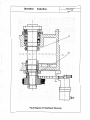
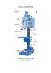
7. The Transmission System of the Lathe
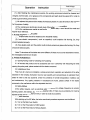
7.1. Description to the Transmission System (See Fig.1)
7.1.1. The main transmission force of the lathe is provided by the Motor, through the band pulley to
the spindle; and the NC system, according the program and through the converter, controls and achieves
the preset spindle speed. And the spindle speed is variable.
7.1.2. Feed Drive System
The driving force is provided by the driving motor located at the left side of the bed, through
Synchronous Band Pulley to Ball Screws, to drive the Slide Carriage for making longitudinal movement
(of Z-Axis);
The driving force is provided by the motor located behind the Carriage, through Synchronous Band
Pulley to Lateral Ball Screws, to drive the Slide Carriage for making lateral movement (of X-Axis);
7.2. Relation Between InstructionS and Spindle Rotating Speed
Operation
Instruction
Total38 Pages
Page 10
I
I
__....~
Fig.1 Diagram of the Transmission System of the Lathe
Operation
Total38 Pages
Instruction
Page 11
The Instruction S value directly indicates the speed value of spindle. After the letter of S, maximally,
a 4-digital number can be entered for the practical spindle speed. It is simple and visual in operating.
For instance: When selecting 500rpm as the spindle rotating speed, entering S500.
7.3. The Detailed List of Transmission Parts of the Lathe (See Table 1)
Table 1. Detail List of Transmission Parts
Descriptions
Number
on
Tooth
Module or
Rotating
No.
Pitch
Direction
Material
Type of Band
Drawings
1
Band Pulley of Motor
HT200
V-Ribbed Belt,
2
Band Pulley of Spindle
HT200
6L--1600
3
Synchronous Band Pulley
35
Circular
of Spindle
4
Arc-Typed
Synchronous Band Pulley
35
Band, 615-5M-9
of coder
5
Synchronous Band Pulley
of
Longitudinal
35
45
5M
Leading
Circular
Arc-Typed
Screw
6
Synchronous
Synchronous
Synchronous Band Pulley
21
45
5M
Band, 350-5M-20
of Longitudinal Motor
7
Pair
of
longitudinal
Ball
5
Right
GCr15
Screws
8
Synchronous Band Pulley
36
45
5M
Band,
of Lateral Leading Screw
9
Synchronous
Synchronous Band Pulley
27
45
5M
285-5M-20
of Lateral Motor
10
Pair of Lateral Ball Screws
4
Right
GCr15
11
Leading Screw ofTailstock
3
Left
45
12
Leading
3
Left
ZQSn6-6-3
Screw
Nut
of
Tailstock
7.4. The Positions of Rolling Bearings (See Table 2.)
· 7.5. The Detailed List of Rolling Bearings (See Table 2.)
8. Main Structure and Functions
8.1. Bed Body and Bottom Case
The bed body of the lathe is made of HT250 cast iron, which is treated with artificial aging for
removing the residual stress and stabilizing the precision of the bed. Its guide rail is treated with
supersonic quenching for enhancing its wear resistance. After the large carriage and working table are
Operation
Instruction
Total38 Pages
Page 12
Fig.2 Diagram of Bearings' Positions of the Lathe
Operation
Total 38 Pages
Instruction
Page 13
Table 2, Detail List of Rolling Bearings
Bearing
Bearing Name
Quantity
Code
Precision
Number on
Class
Drawings
7000103
Deep Groove Ball Bearing
2
PO
1
NN3010K
Double-Row Cylindrical Roller Bearing
1
P5
2
7012AC
Double Direction Angular Contact Thrust
3
P5
3
Ball Bearing
6203-Z
Deep Groove Ball Bearing
2
P5
4
51203
Single Direction Thrust Ball Bearing
2
P6
5
6201-Z
Deep Groove Ball Bearing
1
P5
6
51201
Single Direction Thrust Ball BearingF
1
P6
7
6202-Z
Deep Groove Ball Bearing
1
P6
8
51102
Single Direction Thrust Ball Bearing
P6
9
attached on the wear-resisting guide rail, a scraping and grinding installation is given to ensure the
precision class of longitudinal and lateral feeds, and to guarantee the wear resistance.
The bottom case is made of cast iron by completely casting, which is treated with aging. So, it is
strong in rigidity and good in stability. The bottom case is divided into three sections, left, middle and
right. Inside the left section is located the main motor, which is installed on an adjusting plate. While
adjusting the height of motor, the tension of the band can be adjusted. And the cooling pump and the
cutting coolant tank are located inside the right section.
The front protection cover of this lathe is movable (push- pull door) for achieving safety production in
CNC turning. On the left side of rear protection cover, strong power supply section are mounted,
including driver and converter.
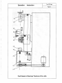
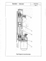
8.2. The Longitudinal Feed Mechanism (See Fig.3)
The Longitudinal Feed Mechanism is mounted at the front of the bed body. The motor (1 ), through a
pair of Circular Tooth Synchronous Band Pulleys (2), drives ball screws (3) , and through the screw nut
bracket (4) fixed on big carriage, makes the big carriage longitudinal moving. The ball screw is supported
by both end bearings; and the pre-fixing of the ball screw is achieved by the tensioning nuts (5), so as to
enhance the rigidity of the ball screw. Zero-clearance mating between the ball screw and its nuts is
adopted. During the operation period, if there are any axial floats on the ball screw, the tensioning nuts(5)
can be adjusted to eleminate the clearance. The
cle-aranc-e-b~etwe~en
big carriage and bed guide rail is
achieved by adjusting the clamp plate under the big carriage. Attention! While adjusting the clamp plate's
position, it must be adjusted to the extent that the big carriage can move but there are neither clearance
nor too tight. If the clearance were large or too tight, the process precision of workpieces would be
Operation
Instruction
Total38 Pages
Page 14
Fig.3 Diagram of Longitudinal Feed Gear
Operation
Instruction
Total38 Pages
Page 15
affected.
For the bearings on both end bearing brackets of the ball screw, while assembling them, a white
special 3# lubricating grease has be applied to ensure the good lubricating capacity during the operating
period. So, there is no need to add any more grease during operating period.
8.3. The Lateral Feed Mechanism (See Fig. 4)
The lateral movement of middle carriage is driven by Motor (1), which drives ball screws(3) through a
pair of Circular Tooth Synchronous Band Pulleys(2), and makes the middle carriage moving through ball
Screw Nut (4) fixed on the middle carriage.
The clearance of dovetail guide of the middle carriage can be achieved by adjusting the oblique iron
through its adjusting screw. Attention! While adjusting the position of the oblique iron; it must be adjusted
to the extent that the middle carriage can move but there are neither clearance nor too tight. If the
clearance were large or too tight, the process precision of workpieces would be affected.
The lateral ball screw is supported by both end bearings. The pre-fastening of this ball screw is
achieved by means of the fastening nut (5). so as to enhance the rigidity of the ball screw. Zero-clearance
mating between the ball screw and its nuts is adopted. During operating, if the ball screw shaft has any
axial floating phenomena, it can be eliminated by adjusting the fastening nut (5) to remove the clearance.
For the bearings on both end bearing brackets of the ball screw, while assembling them, a white
special 3# lubricating grease has be applied to ensure the good lubricating capacity during the operating
period.
If a power tool carrier is equipped on the middle carriage, please read the Operating Instruction of
Power-Driven Turret for its adjustment.
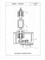
8.4. The Head-stock (See Fig.5)
The internal design of the head-stock of this lathe is of single-spindle structure. For the front
supporting of the spindle, the combination of three D7012AC Angular Contact Thrust Ball Bearings is
adopted; For its back supporting, a DNN301 OKIP5 Double-Row Cylindrical Roller Bearing is adopted;
Additionally, a reasonable supporting distance is used. So, a typical, precise spindle system with high
rigidity and reliability is formed. And these are the key points why the lathe can provide the performance
IJ\I~th tur~i~g_inste~~o! grind~n~in processing wo~kpieces if r~~son_abi~_~LJ_ttil19 arnc>ul'l_t~_?~<ll'l!g_h:_fll11_9!ie>_r1
tools are selected.
The radial clearance of its front bearing can be adjusted by nut (1 ), and the adjustment of back
bearing can be achieved by nut (2). While assembling these bearings, a white special 3# lubricating
grease has be applied to ensure the good lubricating capacity during the operating period. So, there is no
need to add any more grease during operating period.
8.5. The Tailstock
The tailstock is made of HT200 cast iron, which has been treated with aging. The tailstock can move
Operation
Instruction
Total38 Pages
Page 16
Fig.4 Diagram of Cross-Feed Gear
i
I
Operation
Instruction
Total 38 Pages
Page 17
II
Fig.5 Diagram of Head Stock Structure
Operation
Instruction
Total38 Pages
Page 18
along the bed guide rail. Meanwhile, the tailstock can be fixed on any required position by means of an
eccentric mechanism. The offset of tailstock on horizontal surface can be adjusted by means of lateral
adjusting screw.
9. The Cooling System of the Lathe
The Cooling Pump and coolant of this lathe are both inside a independent coolant tank. The spray
nozzle for coolant can be moved to the positions for cooling. The spray nozzle itself can be adjusted for
flow control. After a cooling circulation, the coolant will flow into the chip-receiving tray, and then, after
filtering by means of gauze strainer, it will flow back into the coolant tank for recycling.
10. Lubrication of this Lathe
The librication of lathe is a very important matter, because it has very large influence on the accuracy
and the service life of the lathe. So, the performance of the lubricating parts, the constitution of the
lubrication system, the distribution of the lubricationg points, making correct lubrication and periodical
inspections, cleaning the lubricant tank, checking the lubricating pipe lines, etc., are very important jobs.
For any losses on the lathe, caused by improper lubrication, the responsibilities will be taken by the user
itself..
10.1 For the lubrication of this lathe, it is divided into two sections, manual pump-lubricating, and
pressure-oil-gun lubricating.
10.2 In order to ensure the normal operation of the lathe, the operator should pull the manual pump 2
or 3 times in each shift of work (generally, to keep the lathe under normal working conditions). The oil
level should be checked, often, which should not be lower than normal position. For the detailed
distribution of the automatic lubricating points of this lathe, please refer to Fig. 5 The Diagram of
Lubrication by Oil Pum.
10.3 As for the sections to be lubricated by pressure-oil-gun, they are the two oil cup holes on the
tailstock, and the section contacting with sliding plate under the tailstock. In order to ensure the normal
operation of the lathe, the operator should lubricate them 3 - 5 times with the pressure-oil-gun in each
shift of work (generally, to keep the lathe under normal working conditions).
10.4 Before putting the lathe into normal operation after unpacking its crate, the lathe should be kept
in idle running for several hours and all the sliding parts should be lubricated with new oil. The
manual-control pump should be pulled many times until the lubricating oil coming out from the
chips-scraper. And then, using the pressure-oil-gun to lubricate the oil cup on the tailstock and the section
contacting with sliding plate under the tailstock.
10.5 Maintenance Inspections:
(a) Ordinary Inspection: After starting up the lathe in each shift of work, inspect if there are any leaks
and looses on the lubricating pipeline, any loose-fit on the joints or any damages of the oil cups.
(b) Periodical Inspection:
Check the oil level of the lubricating pump.
11. The Electrical System of the Lathe
Operation
Instruction
Total38 Pages
Page 19
-------~
;:s
0..
0.0
I:
·~
·.E
0
;:s
-
.........
0
··'
Fig.6 Schematic Diagram of Locations by Lubricating Pump
Operation
Total38 Pages
Instruction
Page 20
11.1 For the power supply of the lathe, AC two-phase four-wire system is adopted. The main
parameters of the lathe are as follows:
(1). The Rated Voltage: 220V
(2). Phase Number: two-Phase
(3). Frequency: 50/60Hz
(4). The Rated Capacity: 5Kw
(5). The Rated Input Current Value: 15A
(5). Steady-state Voltage Value: +/-10% of rated voltage
(6). Protection Class: IP54
*This lathe has a reliable grounding system. So, the ground wire of the local power networks must
be directly connected onto the earth terminal inside the power control cabinet for the lathe, to ensure the
safety in personnel and equipment.
11.2 Operating Instruction on the Electrical Circuit of the Lathe (See Fig. 7)
(1). Main Power Supply Switch (QF)
While turning the Switch QF, counter-clockwise, to the position of "0", the power supply to the
lathe is completelt off; While turning the Switch OF, clockwise, to the position of "1", the power to the lathe
is on. When the power indicator HL 1 lights on, it means that the electrical system of the lathe is in ready
state. If any troubles happen on the lathe, the power supply should be switched off immediately. And only
after eleminating the troubles, the power supply can be re-switched on.
(2). How to operate the electrical system of the lathe
a. First, while pressing down the power button of SA1 system, the CNC system will be into
work-ready state; Then, while pressing down the power button of SB1 Servo Driving System, the driving
system and the Spindle Speed Adjusting System will be into working state.
b. When operating the CNC tool carriage (For details, refer to the Instruction of the CNC System},
the power-driven tool carriage will make motions accordingly, such as automatically carrying out the
motor running, tool position changing, locking-in, etc.,
and then, will keep into the tool position preset by
the program.
*This is only effective to the lathe equipped with power-driven tool carriage.
c. When putting the switch SA2 at the position "1", the working light will be on; While setting the
switch at the position "0", the working light is OFF.
d. Operation of the key-board of the CNC system (for details, refer to the Instruction of the CNC
System). Manually operating the keys of "--, t, -, or ~ ", the longitudinal and transversal motion
motors MZ and MX can run to and fro from low speeds to high ones, accordingly.
11.3 Explaination of Electrical Adjustment
a. The fuses FU1 are worked as the terminal short-circuit protection of the electrical system of the
lathe. The breaking current value of short-circuit is 16A.
Operation
Total38 Pages
Instruction
Page 21
+
. !
i
I
Fig. 7 Diagram of Operating Positions of the Lathe
Operation
Instruction
Total38 Pages
Page22
b. The main drving motor M 1 of the lathe is a Three-phase asynchronous motor of Y1 OOL-4.
Rated Power: 2.2 Kw
Rated Current: 5A
Rated Rotation Speed: 1400 rpm.
For the speed regulation of the main driving motor, the frequency conversion is used (refer to the
instruction qf Converter). During the normal operation, the frequency should be controlled within 150HZ in
order to prolonge the service life of spindle motor.
c. For the Motor M2 of power-driven tool carriage, a minitype 3-phase AC motor is used (for
details, refer to the Instruction of Power-driven Tool Carriage). The working operation of the power-driven
tool carriage is controlled by the signals issued by the CNC control box.
*This is only effective to the lathe equipped with power-driven tool carriage.
d. The longitudianl and tranversal travel motors M4 and M5 of the carriage are controlled by AC
drivers; and their feed motions are controlled by the CNC program. KX and KZ are the longitudianl and
transversal stroke limit switchs.
11.4 Maintenance of the Electrical System
The electrical system should be periodically maintained by professional technicians. For the detailed
maintenance procedures, please refer to the following Diagrams and Instructions concerned:
•
The Electrical Pinciple Diagram (refer to Table 3, Fig.8- 17);
•
The Operation Manual of the Converter;
•
The Operation Instruction of Driver;
•
The Operation Instruction of the NC System;
•
The Operation Instruction of Power-Driven Tool Carriage
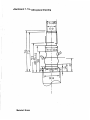
12. How to Hoist up and Install the Lathe
12.1 Hoist up the lathe (refer to Fig. 18)
For hoisting up the unpacked lathe, two pieces of steel tubes should be prepared. Both of them
should be inserted and passed through the hoisting holes of the lathe, and then tie the hoisting ropes on
them for hoisting. While hoisting up the lathe, take mind not to let the steel cable or the hoist chain fixture
touch with the guid rail of the bed, leading screws, spindle and other smooth parts. The paint
surface, should be covere with soft articles in order to avoid to be scratched.
During the procedures of loading and unloading the lathe before and after the transportation, severe
shocks and vibrations should be avoid. While using rolling rods for moving the lathe, the lathe should be
kept balanced, in order to prevent it from overturning for slanting too much.
12.2 the lathe must be installed on a sturdy concrete foundation. The depth of the foundation
normally should be 400 - 500mm. Otherwise, the processing accuracy of the lathe could be affected.
Four pieces of cushion irons should be used under the lathe for supporting the lathe and adjusting its
level.
Pages 23 through 38 have been removed
from this manual due to necessary updates.
This section is unavailable at this time.
Please check our website for future updates they will be posted when they are available.
1/18/2013
This is to certify that the lathe is inspected according
to the Standards concerned, and qualified in precision. It is,
hereby, permitted for delivery.
(attached with precision inspection forms)
Inspection Director:
General
Manager:
Y e ti U i
Total 4 Pages
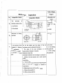
Precision
Inspection Items
No.
Page 1
Inspection
Inspection Sketch
Allowable error
(mm)
a: 0.04/1000
a: Levelling the Lathe
b: 0.02
b:The
Go
straightness
of
b
Slideway within the vertical
plane.
The straightness of Slide
G1
0.015
a.
Carriage moving within the
within
the
total length
horizontal plane.
_Ll -
L....
Run-out at Spindle end
a: 0.01
a: Axial float of the Spindle.
b: 0.015
b:
c: 0.01
Run-out
of
the
supporting surface of the
spindle shoulder.
c: The radial run-out of
centering
shaft
neck
of
spindle.
The radial run-out
of the
a: 0.01 (near the
spindle end)
axis of Spindle Taper Hole
b: (at the place
300mm
to
the
spindle end)
0.02 (for 3-bearing
spindle)
0.025 (for 2-bearing
Spindle)
Total 4 Pages
Precision
Inspection Items
No.
Page2
Inspection
Inspection Sketch
Allowable error
(mm)
The parallelism of the spindle
a: 0.02/300 (only
axis to the motion of the slide
upward deviation
permitted)
I
carriage.
b: 0.02/300 (only
forward deviation
permitted)
The parallelism of the axis of the
a:
tailstock sleeve to the motion of
(only
0.015/100
upward
deviation
slide carriage.
permitted)
b: 0.01/100 (only
forward deviation
permitted)
The parallelism of the axis of the
taper hole of the tailstock sleeve
At a measuring
length of 300:
a:
to the motion of slide carriage.
0.03
(only
upward deviation
permitted)
b:
0.03
(only
forward deviation
permitted)
The
contour
(equal-height)
between the two centers of
0.04
(only permit the
tailstock higher)
spindle and tailstock.
Perpendicularity of cross motion
of tool carriage to spindle axis.
Ga
0.015/100
(deviation
direction
goo )
a
~
Total4 Pages
Precision
Page 3
Inspection
t-N&.- --lnspe&tien--lte:-JR!:;~~---1----Inspee-tion-Sketeh•---I__AU_owable_error_,____
(mm)
Parallelism of the movement of
-:-~,__ 6o.b
---~t --~
tailstock to that of slider.
a. within vertical plane;
a: 0.015
b: 0.02
b. within horizontal plane;
·I I·
Torward/reverse
backlash
of
I
r
G1o
-
z
T
l
(
working table
L
. 1-{11)
I
Longitudinal
7
\
0.04
\
(
I
Cross: 0.03
Half-closed loop
point
I
I
I
l
-
z
The minimum error in the given unit
J
ZAxle:0.01
1-Y)
X Axle: 0.008
Open Loop
IX
ZAxle: 0.01
X Axle: 0.015
Minimum
z
unit x 5
.:;~
G12
l
(
I\
The positioning accuracy of Z
axle and X axle
X
:-~-:
{
X Axle:
a. 0.012
b. 0.013
a: Repositioning Accuracy R;
ball
guideway)
The error of returning the reference
-I
sliding
guideway); 0.02
X
G11
(
:
c. 0.03
b: Reverse Deviation B
ZAxle:
c: Positioning Accuracy A
a. 0.013
b. 0.015
c. 0.032
Given
Total 4 Pages
Precision
No.
Page4
Inspection
Inspection Items
Allowable error
Inspection Sketch
<mm)
The
Pt
accuracy
a:
~
of
finishing outside circle:
)__
a: Cylindricity
.
length
100:
0.01
Ll
b: 0.005
Planeness of finishing
0.02/150
£:; ~
~rd'
'--
0=150
Lmax=30
P3
of
L2
L2
D=20-45
Ll=lOO
end face
a
measuring
r-
b: Roundness
p2
At
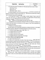
a: the accuracy of the
As for the sketch and the sizes of the test
a: 23 ± 0.02
diameters in finishing
workpiece, see the attached drawings 1.
b: ± 0.03 (sliding
shaft workpieces;
The
sizes
of the
test workpiece
can
be
b: Accuracy in length
appropriately enlarged or reduced.
c: Accuracy in thread
Materials: Brass H62
pitch
(Allowable diameter can be enlarged or reduced in
propotions; the test sample can be used several
times.)
Explaination:
a: ct>23, the difference of the actual measuring.(the
size of ci> 23 can be enlarged or reduced in
--------1--prepeft.iens~
b: Measuring the sizes of the multidiameters
c: Without obvious light slit;
D: Without obvious light slit.
the guide rail}
± 0.015 (rolling
the guide rail)
Attachment 1. Test Workpiece Drawing
1
~·tx 12W
81 cp
·II
j
I
I
j
I
60 '0+£6<1>
M
f'.
'))
(Y)
M
0
0
L[)
+I
0/'
r
I
co (j)yj'
(X) (Y)
~
\
.Ia
I
/
~
£Zcv
~
~
\
')
"'
I
0£<D
I~
"'--_/
Material: Brass
j
\[)
(\J
f"..
~
.......
CNC1315
LATHE
PACKING LIST
Manufacture No.:
MADE IN CIDNA
Packing
Total 1 Page
List
Packing Dimensions: 170 X 105 X 155 em (L X W X H)
G.W.: 1020 Kg
No.
I
-,
N.W.: 920 Kg
Descriptions
1
Main Machine
2
Three-jaw Chuck
3
Tool Carriage
Model and Specifications Qty
KZ125
Remarks
1 set
With its base seat
1 set
Mounted on machine
1 set
Mounted
on
the
Main
Machine (five tool rests)
4
Alloy Center
5
Chuck Spanner
6
Reducing Sleeve
Morse No.3
1
1
JB3477-83
(Outside
#3;
1
Special Order
Inside #2)
7
Double-Head Wrench
8
Inner-hexagon Spanner
13 X 16; 16 X 18; 17 X 19
1 set
3
1
1
9
Pressure Oil Gun
180 cm
10
Rocker
Z7030.2F-05-00
CNC1315
Attached Documents
Lathe
Operation
Instruction;
Certificate
Inspection;
Packing
Operation
11
1
Converter
1 set
of
List;
Manual
and
8 pieces
of
Operation
Manual of Driver
User's
Manual
of
CNC
1
of
1
System
Operation
Instruction
Power-Driven Tool Carriage
12
Taper-Shank of Drill Chuck
ZQ4124-61
1
13
Drill Chuck
JS13
1
14
Wedge
ZQ4124-67
1
15
Press Tool Wrench
10MM
1
16
Alloy Center
Morse No.4
1
Packing Inspector:
: ,.
·. ; ······---·-n
.! ·~r
rr--··--·-·····-··.
_
....__.,;..,__,, _.... ......... -~-
.
Packing Date:
07
2 0 l 2
-·