1
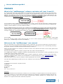
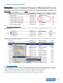
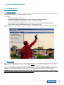
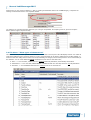
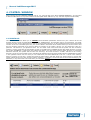
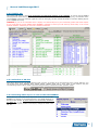
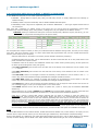
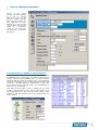
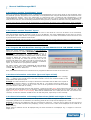
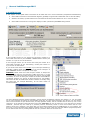
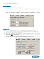
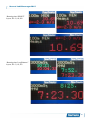
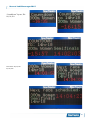
Manual LED SB Manager Version: 2015v3 Table of Contents PREFACE......................................................................................................2 1. INTRODUCTION.......................................................................................3 2. SETUP......................................................................................................3 2.1 2.2 2.3 2.4 Install Location............................................................................................................3 Directory Contents.......................................................................................................3 Running the Application................................................................................................4 Connection Setup.........................................................................................................4 3. OPERATION.............................................................................................5 3.1 3.2 3.3 3.4 3.5 Basic Principle..............................................................................................................5 Intro Screen................................................................................................................5 File Menu: “Show time schedule”...................................................................................6 File Menu: “Show types of datasources”..........................................................................7 File Menu: “Show list of Layouts”...................................................................................8 4. CONTROL WINDOW.................................................................................9 4.1 INPUTS tab..................................................................................................................9 4.2 LAYOUTS tab.............................................................................................................10 4.2.1 Selection of SB-size.............................................................................................10 4.2.2 Selecting which layout is sent to the LED-BOARDS...................................................10 4.2.3 Selecting which layout to EDIT or DELETE or DUPLICATE..........................................11 4.2.4 Selection of EVENT in Time Schedule......................................................................12 4.2.5 How to use the “Participants” layout.......................................................................13 4.2.6 How to use the “Results” layout.............................................................................13 4.2.7 Program SB with RaceTime Settings (IN OUR EXAMPLE FILE FOR SPRINT LAYOUT)..........13 4.2.8 Extra information on Position (Xpos and Ypos of field)..............................................13 4.2.9 Extra information on Rectangle dimensions (Width and Height of field).......................13 4.3 OUTPUTS tab.............................................................................................................14 4.4 SETTINGS tab............................................................................................................15 4.5 TOOLS tab.................................................................................................................15 4.5.1 How to use the “Node programming” feature...........................................................16 4.5.2 How to use the “Font Display Test”.........................................................................16 5. Photos of OUR example layouts, for 3 display sizes..............................17 www.timetronics.be TimeTronics NV Lammerdries-Oost 23B B-2250, Belgium Tel +32 (0)14 23 19 11 Fax +32 (0)14 23 20 24 VAT BE0440 224 404 HR Turnhout 64540 KBC Bank 414-4191871-52 SWIFT : KREDBE22 IBAN : BE64 4144 1918 7152 Manual LedSBmanager2015 PREFACE What is the "LedSBmanager" software, and when will (can) I need it?. If you have bought triple-color LedScoreboard(s) of TimeTronics, and you only want to show during the races the Running time, Split time(s), and unofficial finish time, you do NOT need the LedSBmanager, because such timingdata can be sent DIRECTLY from MacFinish. This is because the TimeTronics Led-BOARDS are compatible with the (well-known but old) MacFinish scoreboard protocol “IE 1.0.1”. And each Led-BOARD is factory-programmed to display such “Running or split or finish time” on a fixed defined setting; like position, size, font and color of this timing text. You can choose in MF to update the timing display 1/sec or 10/sec ! And if you ever would like to change the fixed programmed color (red/green/yellow) of this time-display on your ledboard, you could do this by using the LedSBmanager software. And this software is (currently) FREE OF CHARGE ! But the LedSBmanager2015 can do much more, at least IF your Led-BOARD is big enough to show more than this timing information only ! The LedSBmanager2015 can receive over the ethernet computer network all live timing information of a selected MacFinish camera, and the operator has control over USER-PROGRAMMABLE layouts to display TEXTmessages, TIMING-data, PARTICIPANT-lists, RESULT-lists, INFORMATION of NEXT-race, etc. So this LedSBmanager software can be used as an extra software running on the MacFinish computer, or on any other (WIN) PC in your computer network. Please make sure that you have a serial connection (COM-port, or wireless connection) between your “LedSBmanager PC and the Led-BOARDS !! Welcome to the "LedSBmanager" user manual. May we recommend you to gently leaf through the entire manual first, just to have an initial idea of how the book is structured. As we cannot possibly explain all details simultaneously, this might help you a bit in understanding and tracing things back. Of course, the table of contents will also help you in doing so. Please note that all pictures are examples, the delivered version can be different than shown in this manual, please inform yourself before purchase. Also take note that this software is a work in progress. Not every option is fully developed yet. The LedSBmanager software is available for Windows operating systems only. We provide no working guarantee for running LedSBmanager using emulation tools like Wine. If you, after reading this document, have any further question regarding the operation or service of this or any other TimeTronics equipment, please contact your local distributor or TimeTronics directly, by email: info@timetronics.be, or call us at +32 14 231911 Please also contact us if you have any remarks or advise regarding this user manual: info@timetronics.be. Good luck with LedSBmanager and thank you for your confidence in the TimeTronics products and services. The editors. © Copyright 2015 TimeTronics. All rights reserved. TimeTronics Lammerdries 23b B-2250 Olen Belgium Tel.: +32 (0) 14 23 19 11 Disclaimer Under no circumstances shall TimeTronics be liable for any loss, damage or expense suffered or incurred with respect to any defective product. In no event shall TimeTronics be liable for any incidental or consequential damages that you may suffer directly or indirectly from use of any product. Microsoft Excel, Windows, Windows XP , Windows VISTA and Windows 7 are registered trademarks of Microsoft Corporation. 2 Manual LedSBmanager2015 1. INTRODUCTION Scoreboards are evolving. A decade ago, most still consisted of combinations of simple 7-segment NUMERICAL displays. Now LED matrix displays are the de facto standard, preferably in MULTIPLE COLORS. TimeTronics offers a variety of boards differentiating in sizes, colors and capabilities. When used for RACES (name of race, time of day, racetime, etc) these Led-boards are controlled by the LedSBmanager application. This manual offers a guide through the different menu's and user interface of the software. We will continuously use the word “datasource”. A datasource in this LedSBmanager program is one of many types of “data fields” which can be integrated in each layout, to form a total display on your Led-boards. An example of a simple and fixed datasource is a “Text” type, for which you can enter a fixed text, like “Welcome” or the name of your meet or city. An example of a variable information can be a “Daytime” datasource field, which will show the Time-of-day of your PC. A last example of a variable datafield can be a “RaceTime” datasource which comes from a MacFinish photofinish, or a “ScheduleTitle” which comes from a user-selection in the TimeSchedule window. Warning: MacFinish photofinish data is used for several datasources. To properly use the functions described, the TimeTronics MacFinish software version 7.7.2.17 (for MacFinish ethernet cameras) or MacFinish software version 8.0.0.50 (for MacFinish USB cameras) or later version is required. Warning: The RaceTime datasource update speed of 10 Hz (=10x/sec) is only for TimeTronics Led scoreboards with firmware version 3.21 or higher, and to use this speed, the settings (FONT,COLOR, POSITION etc) of this RaceTime datasource have to be “Programmed” by this software in advance in each Led-board. Please read chapter 4.2.7 for this programming ! 2. SETUP 2.1 Install Location You will first have to “unpack” (Unzip) the downloaded software, and place it somewhere on your PC harddisk. The LedSBmanager application is “portable”, which means it can be unpacked from it's archive file, and then placed on your harddisk wherever the user desires, assuming that the operator has read&WRITE access to the harddisk location that is chosen. The recommended location though, is in the system's “Program Files” directory, under “TimeTronics”, e.g. “C:/Program Files/TimeTronics/LedSBmanager2015/”. To place the folder in the Program Files directory, you might need elevated (administrator) privileges on your current host system. In that case, either install the application to your home folder (e.g. “C:/Users/JohnDoe/LedSBmanager 2015/”), or contact your organisations IT administrator. 2.2 Directory Contents In the folder you have just installed, two subdirectories are available, one called “Demo Datafiles folder” and one called “LedSBmanager software”. The first folder initially contains a demonstration (4D-database) datafile that you can use to start using your LEDscoreboard. Step by step you will/can (but do not have to) make changes to the default settings of the software, to personalise the usage of the software. The second folder contains the actual LedSBmanager software used to control the LED boards. In this way, it is possible to back-up your personalized LedSBmanager settings and layouts by simply copying the folder “Demo Datafiles folder” to a secure directory. 3 Manual LedSBmanager2015 NOTES for later; If you ever want to BACKUP or DUPLICATE your current (LedSBmanager database) datafile, copy ALL 3 files which have the name of your current datafile (in the example below = “datafile LedSBman ALLsizes”), so copy and keep together the files “xxx.4dd” + “xxx.4DINDX file” + “xxx.MATCH File”. You can rename these files to any other chosen name, as long as you rename all 3 files with same new name. If you want to USE a (renamed) other datafile, press IMMEDIATELY the “Alt” key on your keyboard AFTER you started up the LedSBmanager program. You will then see a window to select another datafile. 2.3 Running the Application The LedSBmanager executable file (application) is found in the sub-folder “LedSBmanager software” and is called “LedSBmanager.exe”. For easy access in the future, you could add a shortcut to your desktop by right-clicking the executable, choose “Send To” and selecting “Desktop (create shortcut)”. 2.4 Connection Setup Start the LedSBmanager application (see 2.3 Running the Application). If you set-up the cables correctly, you are greeted by a message similar to “The serial port nr:3 is now opened for SB-communication.” If this is not the case, re-check your cabling or serial port selection setup (see later in this manual in chapter 4.3). Click OK to continue. The board should now display the first LED layout it has found (“Welcome”, ID 0 by default). If everything checks out okay, we can now begin to start using the LedSBmanager application. 4 Manual LedSBmanager2015 3. OPERATION 3.1 Basic Principle LedSBmanager uses a defined set of rules called “layouts”. By utilizing these layouts, LED board operators can display different groups of information at different stages in the event. For example: • Welcome message + current time • Name and scheduled time of next race or other event (like “Opening Ceremony”) • Listing of participants (In “Slide-Show” mode = one athlete at a time) • Race timing information (like RaceName, Live Racetime, Time of first finisher, Windspeed, etc) • Listing of race results (In “Slide-Show” mode = one athlete at a time) Manipulating these layouts (designing, using and modifying them whenever you want) is what LedSBmanager is designed for. 3.2 Intro Screen When you start LedSBmanager you will see a window like shown above, with a photo of a real (400m) race. The starter is visible, but also a LEDscoreboard used for timing, and a possible layout to show the name of the race and the live Racetime. Using the “File” menu (see picture above), different parts of the program can be accessed. The majority of operation will be in the “Show CONTROL WINDOW” item and is further explained in chapter 4. CONTROL WINDOW. We will now first explain the other menu-items which occasionally can be usefull, but definitely will be less used and less important. IMPORTANT NOTE; When switching between menu-items, first close the current window (so that you again see the photo like above), then select a different menu-item. 5 Manual LedSBmanager2015 3.3 File Menu: “Show time schedule” This menu selection will show a window with your current list of events and time schedule. You can MODIFY this list, using the “Add” and “Delete” button, and you can EDIT a specific item by “double-clicking” that item. You can also “IMPORT” such list with the Button “Import from File...” from a simple “.TXT” type of file, which you can create with (preferably) a spreadsheet program, like “Microsoft Excel” or “OpenOffice or LibreOffice Calc”. You can find an EXAMPLE of such .txt file (named “DEMO schedule for IMPORT”) in the folder “Demo Datafiles folder”. Use the button “Close window” if you are ready with this schedule list, and want to close the window. When importing a new “Time Schedule” .txt file, do not forget to display all “.TXT” type of files (see bottom right of picture below). In the next screen, do not forget to select the TABLE for import as “TimeSchedule”. See picture below; 6 Manual LedSBmanager2015 Furthermore you can choose to Append (= ADD to existing TimeSchedule data in the LedSBmanager), or Replace the existing TimeSchedule with the new imported datafile. You will then see a window with the data from your .txt type of importfile. If everything looks ok, press the “Import” button (bottom right of import window) 3.4 File Menu: “Show types of datasources” This window shows you which possible DATASOURCES can be used to fill a layout of the LED display boards. It is usefull to study these different types, and their meaning, to get a good idea what can be shown. Editing this list is NOT possible, to make sure that the coding of these items can not (accidentally) be changed, which would prevent a correct functionality of the software. You can notice different groups of datasources, like the one that start with ; “Race...”= Live race-data; TIMING from the selected MacFinish photofinish, automatically transmitted. “ParticResult...”= Live race-data; PARTICIPANTS or RESULTS which are manually sent from any MF photofinish. “Schedule...”= Live SCHEDULE-data from the selected event in the schedule list. 7 Manual LedSBmanager2015 3.5 File Menu: “Show list of Layouts” This window shows you which LAYOUTS currently are available in the datafile. You will notice that we have created 3 “groups” of display board sizes, with 64x24, 64x40, 128x40 pixels, respectively for a small (max 3 lines) LED board, a larger (max 5 lines) LED board, and 2pcs of the larger (max 5 lines) ledboards (horizontally next to each other). We have made our own preferred layouts with settings for these different sizes of boards, but you will understand that it is possible for you to make modifications, or your own layout(s) with your preferred settings. Use the bottom-right icon to create a totally new layout. In this window you can only EDIT the name, ID and size of each layout, after double clicking on a layout. If you want to delete (one or more) layout(s), you can select them (click and shift-click with mouse to select a range) and use the button with the green text “DELETE selected layouts”. No warning is given after clicking this button !! 8 Manual LedSBmanager2015 4. CONTROL WINDOW When opening the main CONTROL WINDOW (see ch. 3.2; using the File menu “Show CONTROL WINDOW”), you will notice 5 different TAB buttons on top of the window. We will explain these TABs one by one, and their respective functionality. 4.1 INPUTS tab This leftmost tab-control allows you to CHOOSE which MacFinish photofinish camera from your network will be the ACTIVE camera to send the LIVE RACE TIMING to the LedSBmanager, and therefore also to the Led-boards. Just make sure that you click on the camera that you want to use from that moment on. In the example below the camera with serial number “00-00-30” is activated (blue row), this is also visible in the header of the window where you see the serial nr and the live racetime of that MF. If you click (for about 2 seconds) on the “Name” column, you can change the name of a particular MF-camera to your preferred name. You can delete a MF record from this list (select one and use button “Delete”), but the great thing of this software is that you do NOT have to CREATE this list with YOUR camera(s) yourself, this is fully AUTOMATIC ! Continuously the software will “listen” over the entire network (within IP-range) to connected MacFinish cameras, and update this list with new camera(s). Of course the MF7.x or MF8.x will have to be running, because it is not the camera itself, but the controlling MF-software which will communicate with the LedSBmanager. Notice in the rightmost column “On air?” that you can continuously see there WHICH MF is “On air” = active in the network. When it is active you will see a (small) dot inside the radio button, and that whole row will be shown in normal color (black) instead of the grey color used for inactive camera(s). Conclusion; You do not have to fill in serial number(s), IPaddresses, or any other code to find and select your MacFinish camera. 9 Manual LedSBmanager2015 4.2 LAYOUTS tab This second tab-control is the most used and most important window of the software. It can be used to SELECT which layout has to be sent live to the Led-boards (Dark-blue area on the left named “Display layout”), the selection of the current EVENT in the Time schedule (Light blue area on the right), but also to EDIT all details of a chosen “Editing layout” (in the GREEN text areas). WARNING; If you do not immediate have a display of a selected layout on your Led-boards, please first check chapter 4.3 to verify that the correct SERIAL PORT NUMBER is selected to control your led board by serial cable, or the correct wireless interface selected if you use such a wireless connection. We will now explain the different elements of this window; 4.2.1 Selection of SB-size First select which size of Led-display board(s) that you have, by clicking in the pull-down list to the right of “SB-size”. You can choose from three different sizes; 64x24, 64x40, 128x40 pixels (Hor x Vert). After a new selection only the corresponding layouts will be visible in the blue and green lists, to make the further operation easier. 4.2.2 Selecting which layout is sent to the LED-BOARDS At any time you can select which layout has to be sent to the LEDBOARDS, by clicking on the desired layout in the DARK BLUE list on the left of the window. All other features are intentionally disabled in this blue list; in this window you can NOT edit the name of the layout, delete a layout, create a new layout, change the order in the list, etc … 10 Manual LedSBmanager2015 4.2.3 Selecting which layout to EDIT or DELETE or DUPLICATE In the GREEN list of layouts you can select a particular layout for ; EDITING ; Change Name of layout (long click), but also add, remove or modify datasources and settings (in bottom window) DELETE; Select a layout to be deleted, and use button “DELETE selected layout”. DUPLICATE; Select a layout to be duplicated, and use button “DUPLICATE ...”. Then type #copies and first Idnr of the new layout. After each click (=selection) on another layout in the green list, you will see that the components of that layout (DataSources) and their settings (Font, Color, position, rectangle size, etc) are updated in the bottom window ! EXAMPLE; When you selected the first layout in the size 64x40 pixels (“Welcome” layout, with ID=0), you see the components and settings from the picture below ; We will explain this example in detail, to make you understand what the different settings mean, and how you can change them later. This layout contains 4 items: 3x “static” TEXT-fields with programmable text, and one variable field with the daytime (time-of-day of your computer). Each of these fields is “Activated” to be shown (Column SHOW is selected by checkbox). 4 different FONT sizes are used, just for demonstration. “B=6x8” means that font “B” is used, which takes 6 Led pixels horizontal and 8 pixels vertical. 3 different colors can be chosen. The LEDboards contain only 2 colors of leds (red and green), but also yellow can be shown by illuminating both colors (red+green). The HOR. POSITION (pixel number from the LEFT side of the board) of the datasource can be chosen in the “----->” column. The VERT POSITION (pixel number from the TOP side of the board) of the datasource can be chosen in the next column. The HOR SIZE (width of a rectangle to enclose the contents) of the datasource can be chosen in the “<--->” column. Any parts of the datasource display OUTSIDE this rectangle will NOT be shown ! The VERT SIZE (height of a rectangle to enclose the contents) of the datasource can be chosen in the next column. Any parts of the datasource display OUTSIDE this rectangle will NOT be shown ! The ZOOM factor can be used to enlarge the chosen datasource. Do not forget to make the hor and vert size of your 'rectangle' bigger, in case you use larger fonts or use a zoom-factor. The SPEED selection can be used to change an update rate; 1x/sec or 10/sec (only for MacFinish RACETIME datasource). Each datasource can contain a PREFIX and/or SUFFIX user-programmable textfields. A prefix means that this optional text will be shown IN FRONT of the datasource, a suffix will be shown AFTER the datasource. The “S.a.f.” column (=“Show After Finish”) indicates that you want to continue to show the update of a RACETIME field after the finish of the first athlete. Mostly used (like in our demonstration file) only for long distance races, where you want to show the unofficial (photocell) time of the winner, but also want to continue to show the running time of the race for the other athletes which did not yet finished their race, and perhaps still have 1 or 2 laps to go... Warning; If you use this “S.a.f”-feature in your own (new) layout(s), make sure that the racetime and first finishtime datasources do not overlap, in part or complete. The reason is that you can not show two different datasource fields at the same time on the same position. In the example of the SPRINT layout both mentioned fields are programmed at the same position on the Ledboards, but for sprint races it is not usefull to let the time display continue after the finish of the winner, so switch off the “Saf” option for a SPRINT race display. Notes; To ADD A NEW datasource in the bottom window, double-click below the bottom row, in other words, in an empty row. You will then see an “Input window” where you can choose the type of datasource, and all further mentioned settings. Some of the settings of a datasource (like zoom,speed,show,position,size and S.a.f) can be edited directly in the bottom window, the other settings can be edited in the “Input window” after double-clicking on the row of the datasource. 11 Manual LedSBmanager2015 Picture of the “Input window” to edit the settings of a new or existing datasource. Here you can edit ALL detailed settings. Note that some fields are only applicable for some datasources ; like the field “Text to show” can only be edited for a datasource “Text”, and “S.a.f. can only be edited for a “Racetime” datasource. 4.2.4 Selection of EVENT in Time Schedule In this part of the window you can select the CURRENT or NEXT or PREVIOUS event (depending if you want to show a layout with the racetimes of the CURRENT event, or a layout with the scheduled time and name of the NEXT event, or the slideshow results of a PREVIOUS event). The datasources beginning with “Schedule...” (like ScheduleTime, ScheduleTitle,...) will take the contents from the selected event in the TimeSchedule to display on your Led-boards. Fast changes of the time or title or subtitle can be made directly in the schedule list (click, wait and click again), or by fast double-click in the list to see the input window of the schedule to edit any particular item in the TimeSchedule (see picture below). 12 Manual LedSBmanager2015 4.2.5 How to use the “Participants” layout When you choose the “Participants” layout, a slideshow of all participants of a race can be shown on the Led-boards, when the MacFinish operator will press the “F4” functionkey on the keyboard when using the MF software (MF window has to be active=frontmost window). This is the MF-function to communicate with a TimeTronics MM (MeetManager) or AM (AthleticsManager) software, and to ask for the participants of the next race. This is normally done when the athletes are ready for their next race, and are standing behind their starting blocks (or behind the start line in the long distance race). As soon as the MF has received this list of participants, it will send this list further to the LedSBmanager, which will display this list (in a slideshow mode= one by one, one screen for each athlete) on the Led-boards, IF a “Participants” layout is selected manual or automatic. The automatic switch-over to a participants layout is explained in the chapter 4.4. Also the delay period between each “slide” of the slideshow is programmable, and explained in same chapter 4.4. 4.2.6 How to use the “Results” layout When you choose the “Results” layout, a slideshow of recent or old results of a race can be shown on the Led-boards, when the MacFinish operator will send a result of one or all athletes. The result of ONE athlete is sent when you click in the MF-photo (with “Cntrl” button on keyboard pressed at same time). The results of all athletes of that race can be sent by the MacFnish menu-selection “Send results”. As soon as the MF has sent the result(s) to the LedSBmanager, this last one will display this data (in a slideshow mode= one by one, one screen for each athlete) on the Led-boards, IF a “Results” layout is selected manual or automatic . The automatic switch-over to a result layout is explained in the chapter 4.4. Also the delay period between each “slide” of the slideshow is programmable, and explained in same chapter 4.4. 4.2.7 Program SB with RaceTime Settings (IN OUR EXAMPLE FILE FOR SPRINT LAYOUT) When your layout contains a datasource of type “RaceTime” which you would like to display 10 times/sec, you need to PROGRAM the Ledboard(s) to remember ALL the settings of that Racetime (Like FONT, Color, Position, dimensions). This is necessary because otherwise the display board would not be fast enough to display the running time 10x/sec. Because such settings can be kept the same all the time, they can be programmed ONCE in the board, and will be memorised by the board. Of course if you would change the setting in a Racetime layout, you would have to reprogram the ledboard. For safety reasons, this button “PROGRAM SB with Racetime settings” is only visible if you selected a “Editing layout” which includes ONE “Racetime” datasource. Note; All available boards that are connected can be programmed with this function at the same time. 4.2.8 Extra information on Position (Xpos and Ypos of field) Xpos and Ypos determine the starting position of a displayed text (any alphanumeric text= message, time, ...) relative to the top-left pixel of the LED scoreboard. Text is then rendered relative to the pixel selected with Xpos and Ypos. Example: This LED scoreboard is 10x10px in dimensions. Remember that the LED in the top-left of the board is at position called 0,0. A datasource with font “A = 5x7 pixels” and text to show “A” is created. Xpos is set at 1, Ypos is set at 2. This is how it will be generated on the LED scoreboard (the white square is also dark in real life) The white pixel here signifies where the text will start: 1 pixels to the right ( Xpos) and 2 pixels to the bottom (Ypos) of the top-left-most pixel of the board. The “A” character is displayed starting at the white pixel and is 5 pixels wide and 7 pixels high (font “A=5x7” chosen in this example). Note that the ledboard will use 1 blank pixel hor and vert between each character, so that each character of FONT A=5x7 will take 6x8 pixels, respectively hor and vertically. 4.2.9 Extra information on Rectangle dimensions (Width and Height of field) Width and height can be used to achieve a “crop” effect. If the width or height is smaller than the amount of pixels required to generate a line of characters, the remaining pixels will be cut off, and not displayed as a result. Example: A single line text datasource with text “TimeTronics” and font A = 5x7 has given a width of 30 and a height of 8. The result is the LED scoreboard only displaying “TimeT”; because max 5 chars can be displayed on the width of 30 pixels (30/6=5). NOTE : When a character can not be displayed fully, the entire character is not displayed. E.g.: a cropped “L” will never display as “I”. 13 Manual LedSBmanager2015 4.3 OUTPUTS tab In this chapter we will explain which connections can be made with one or more Led-boards (and optional old NUM board). Serial cable connection to all Led-boards together (probably trough the MF-interfacebox and 12-wire MF cables). Wireless connection, by WIFI network and a TimeTronics Wireless serial interface for one or each Led-board. Serial cable connection for running-time display on older (TimeTronics) NUMERIC timing boards. In the top-leftt section you can choose the serial port number for a serial cable connection to your NUMERIC TIMING-boards. Choose port number “0” if you do not use this feature. In the top-right section you can choose the serial port number for a serial cable connection to your Led-board(s). Choose port number “0” if you do not use this feature. If you do not know which is the number of your serial port interface(s) (probably a USB-to-serial interface), look in the “Device manager” of your WINDOWS machine. See picture on the right. WARNING; Please make sure that the port number is always less than 10, so you could use any serial port (“COM”-port) from 1...9. And of course please realize that each serial port can only be used for ONE connection, so never use same port number for Numeric board AND for Led-boards, because you will get an alarm that this is not possible. This alarm will also be visible when another software is already using this serial port (for example MacFinish), for the same reason as mentioned above. The list of Wireless interfaces is filled automatic, just like the list of MacFinish cameras (see chapter 4.1). You can enable one or more interfaces by setting the corresponding check-box, and see which interface(s) are “On-air”. You can edit the name of each interface to your desired name, for easy operation. NOTE; Such an interface can be driven by one or more computers, so the limitation mentioned above that each serial port can only be used once is not valid here for wireless interfaces , because they are linked by a (wireless) network connection, which is much more modern than an “oldfashion” serial port in windows ! This means that you could install multiple copies of LedSBmanager on your network, and drive one or more Led-boards from different locations (PC's). Of course, make sure that the different programs/operators do not disturb each other by sending different data to a particular board at the same time ! 14 Manual LedSBmanager2015 4.4 SETTINGS tab In this chapter we will explain which general settings can be made ; Change the light intensity of the Led-boards; low value (f.e. 15) for nighttime and high (f.e. 95) when full sunshine Choose the DELAY-period between each slide-show screen in PARTICIPANTS or RESULTS layout mode. Example 3500 msec = 3,5 seconds Enable the AUTOMATIC switching to another layout (number to be chosen, or 0 value if not used), to Participants, Race, or Results layout number, if the activated MacFinish is in such corresponding mode. This means in the example picture below that the LedSBmanager will switch automatically to the Results-layout (nr 4) when a MacFinish on the network will send one or more athlete RESULTS (by click in photo, or “Send results” menu selection). 4.5 TOOLS tab In this chapter we will explain which software tools can be used, for example to test cabling and/or Led-boards ; “Led display testing”; Press buttons “Start LED test” for showing a “SHOW” of rows and columns of lighting leds. “Clear SB” button to clear the whole Led-board screen(s). “LED SB NODE programming”; type numbers X/Y for programming ONE board to ROW “X” and COLUMN “Y”. Normally you do not have to use this feature, because when you have only one board (for each display position on your track), keep each board on Node-nr 0/0. FONT display test; You can show a list of characters on the Led-boards, in a chosen FONT, on chosen start position (Xpos/Ypos), from “Start char” to “End char” (ASCII codes in decimal format ; A=65, B=66,...) 15 Manual LedSBmanager2015 4.5.1 How to use the “Node programming” feature When using a set-up with multiple inter-connected LED scoreboards next to each other, each scoreboard (“node”) can be programmed individually, so that multiple boards act together as “ONE LARGE BOARD”. Edit the first value (before the slash “/” sign) to edit a node on the vertical axis (ROW), and the second value (after the slash “/” sign) to edit a node on the horizontal axis (COLUMN). Example: Node 0/0 Node 0/1 Node 0/2 Node 1/0 Node 1/1 Node 1/2 Warning: Only connect one LED scoreboard at a time when programming, because all connected (and powered on) scoreboards will be programmed with the chosen node number X/Y. 4.5.2 How to use the “Font Display Test” Because a LED scoreboard works with a matrix of LED's, it's resolution is limited. As a result, fonts need to be specially adapted to displaying characters using a minimal amount of pixels. Use the FONT display test to try out how different fonts look on the board. Options: Option Description Font Select a font to use the test with. Currently, about 15 different fonts (A,B,..) are available. Xpos Start generating the test text on this x position. Ypos Start generating the test text on this y position. Color Selects a color in which to display the font (default: red). Currently, only red, green and yellow are available. Start char Starting character ASCII value (default: 64, meaning '@'). End char Ending character ASCII value (default: 100, meaning 'd'). The result of the standard settings font display test: 16 Manual LedSBmanager2015 5. Photos of OUR example layouts, for 3 display sizes Reminder; If you want to use 2 (or more) Ledboards next to each other, please program them (see chapter 4.5.1) first with their corresponding ROW (=0) and COLUMN (=0,1,2..) number ; see photo on right : Here below you see each time 3 examples of same layout-type, but for different sizes of Ledboards. Smallest is one board of (HxV) 64x24 pixels, middle version= 64x40 pixels, largest example shows 2 boards of 64x40 pixels = total of 128x40 pixels display. As each pixel is 20mm or 2 cm, the largest display area (the boards themselves are larger) is 128x20=2560mm wide = 2m56 and has a height of 40x20=800mm = 0m80. Note that there is no limitation to place more than 2 boards next to each other to create larger display areas ! “Welcome” layout, ID=0,100,200 17 Manual LedSBmanager2015 “Running time SPRINT” layout, ID= 2,102,202 “Running time LongDistance” layout, ID= 3,103,203 18 Manual LedSBmanager2015 “CountDown” layout, ID= 10,110,210 “Next Race” layout, ID= 20,120,220 19 Manual LedSBmanager2015 Good Luck with your operation and use of the LedSBmanager application ! If you have whatever question or advise to us concerning this user manual. Please contact us by email on info@timetronics.be © Copyright 2012...2015 TimeTronics. All rights reserved. TimeTronics Lammerdries-Oost 23b B-2250 Olen Belgium Tel. : +32 (0) 14 23 19 11 Fax : +32 (0) 14 23 20 24 20


![English [2012v1]](http://vs1.manualzilla.com/store/data/005994732_1-5b50c16b769d7d14a751f578cdbfd574-150x150.png)


![English [2015v1]](http://vs1.manualzilla.com/store/data/005829431_1-1fdc30543d444fb0915a40c3aab945a8-150x150.png)


![English [2012v1]](http://vs1.manualzilla.com/store/data/005770981_1-8c196de42073f8db3e58cd387e9490be-150x150.png)
![English [2012v1]](http://vs1.manualzilla.com/store/data/005857990_1-ba5aca9850e0a37c2eb2dd5a5d355973-150x150.png)

![English [2012v1]](http://vs1.manualzilla.com/store/data/005666127_1-015c2c1b906ab908850f1f1f8721a849-150x150.png)