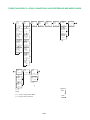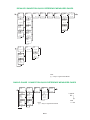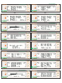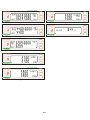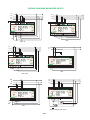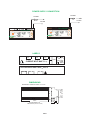
1
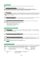
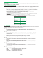
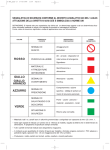
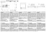
Via Vizzano 44 - 40037 Pontecchio Marconi (Bologna)Italy Tel. +39 051 6782006 - Fax +39 051 845544 http://www.elcontrol-energy.net e-mail: Italia vendite@elcontrol-energy.net estero: sales@elcontrol-energy.net ENGLISH STAR3 din STAR3 din ALM Energy & Harmonics Analyser USER MANUAL WARNING Elcontrol Energy Net S.p.a. declines all liability for any damage to people or property caused by unsuitable or incorrect use of its products. Elcontrol Energy Net reserves the right to change product specifications without prior notice. 3YYYB113 STAR3 Din User Manual Eng Rev. 02/2005 THREE PHASE (DELTA / STAR) CONNECTION, QUICK REFERENCE MEASURES PAGES 2 AL1 AL2 AL3 VL1 VL2 VL3 Fig.1 Fig.4 A NeutraL VL1 VL1Min VL1Max AL1 AVG AL2 AVG AL3 AVG VL2 VL2Min VL2Max Fig.3 VL3 VL3Min VL3Max Fig.3 varL1 varL2 varL3 Fig.10 Fig.9 Fig.11 PFL1 PFL2 PFL3 Fig.12 V THD% A THD% Fig.13 VL1 THD% VL2 THD% VL3 THD% SEL VL1 vL2 VL3 Delta (***) Fig.2 Fig.3 VAL1 VAL2 VAL3 WL1 WL2 WL3 Fig.5 Fig.14 AL1 THD% AL2 THD% AL3 THD% Fig.15 Fig.6 ALI MD AL2 MD AL3 MD Fig.7 AL1 AL1Min AL1Max Fig.8 AL2 AL2Min AL2Max Fig.8 AL3 AL3Min AL3Max Fig.8 1 VA var W Hz Fig.17 VA AVG W AVG var AVG Fig.18 kVAh kWh kvarh kWh Fig.20 2 Fig.21 kvarh COG kWh COG (**) SEL VA MD W MD var MD Fig.22 Fig.19 Legend: SEL Note: (**) Only in cogeneration Mode PAG (***) Only in Star connection PAG.1 V W A PF Fig.16 1 DIPHASE CONNECTION QUICK REFERENCE MEASURES PAGES VL1 vL2 2 AL1 AL2 Fig. 1 VL1-L2 Fig. 23 VL1 VL1Min VL1Max Fig. 3 VL2 VL2Min VL2Max Fig. 3 VAL1 VAL2 WL1 WL2 Fig. 4 Fig. 9 varL1 varL2 Fig. 10 PFL1 PFL2 Fig. 11 Fig. 12 AL1 AVG AL2 AVG V THD% A THD% V W Fig. 13 A PF Fig. 16 VL1 THD% VL2 THD% Fig. 6 Fig. 14 AL1 THD% AL2 THD% ALI MD AL2 MD Fig. 15 Fig. 7 AL1 AL1Min AL1Max Fig. 8 AL2 AL2Min AL2Max Fig. 8 VA var W Hz 1 Fig. 17 kVAh kWh kvarh kWh Fig. 20 2 Fig. 21 kvarh COG kWh COG (**) VA AVG W AVG var AVG Fig. 22 Fig. 18 VA MD W MD var MD Fig. 19 Note: (**) Only in cogeneration Mode SINGLEPHASE CONNECTION QUICK REFERENCE MEASURES PAGES 1 V A W PF Fig.16 V V Min V Max Fig.3 A A Min A Max Fig.8 VA var W Hz Fig.17 VA AVG W AVG var AVG Fig.18 VA MD W MD var MD Fig.19 kVAh kWh kvarh kWh Fig.20 V THD% A THD% Fig.21 kvarh kWh 1 Fig.13 COG COG (**) Legend: SEL Fig.22 Note: (**) Only in cogeneration Mode PAG.2 PAG 1 SETUP PAGES (ALL MODELS) PAG + SEL PAG PAG PAG +SEL PAG (30 SEC) Fig. 26 Fig. 25 Fig. 24 PAG PAG PAG Fig. 27 Fig. 28 Fig. 29 PAG PAG PAG Fig. 30 PAG PAG Fig. 31 PAG Fig. 32 SETUP 4-20mA / ALM Fig. 33 SETUP PAGES ALM VERSION PAG Fig. 42 1 From the Common Setup Pages PAG Fig. 43 Fig-36 PAG 2 PAG PAG Fig. 37 Avaible measures for alarms kvar kWavg kVAavg L1 L2 PAG L3 Fig. 39 Tab. 1 PAG Fig. 40 1 Chosing 100mSec 2 Chosing relay PAG Fig. 41 PAG To measures pages PAG.3 THD% A kVA Fig. 38 THD% V A kW TOT PAG COS F (PF) V 2 DISPLAYED MEASUREMENT PARAMETERS Phase-neutral Voltage Voltage [V] T OT L2 L1 Phase-phase Voltage Voltage [V] L3 L1-L2 L2-L3 Minimum Voltage Voltage [V] Maximum Voltage Voltage [V] L3-L1 Current [A] Power Factor Frequency [Hz] A verage Current [A] Minimun Current [I] Maximum Current [I] Maximum Demand Current [I] N Active Power [kW] Reactive Power [kvar] Apparent Power [kVA] [kVA] A verage Active Power [kW] A verage Reactive Power [kvar] A verage Apparent Power [kVA] [kVA] Maximum Demand Active Power [kW] Maximum Demand Reactive Power [kvar] Maximum Demand Apparent Power [kVA] [kVA] Positive (Imported) Active Energy [kWh] Cog-negative (Expo) Active Energy [kWh] Positive Reactive Energy [kvarh] Cog-negative Reactive Energy [kvarh] Apparent Energy [Kvah] Current Thd% Voltage Thd% HARMONIC ORDER (k=1..25 @ 50Hz - k=1..20 @ 60Hz) L1 L2 L3 HARMONIC VOLT VOLTAGE VK HARMONIC CURRENT IK PAG.4 STAR3 din MULTI PANEL METER PAG STAR3 din MULTI PANEL METER PAG 10Wh 10Wh SEL SEL SET SET Fig.9 Fig.1 STAR3 din MULTI PANEL METER PAG STAR3 din 10Wh MULTI PANEL METER PAG 10Wh SEL SEL SET SET Fig.10 Fig.2 STAR3 din MULTI PANEL METER PAG STAR3 din MULTI PANEL METER PAG 10Wh 10Wh SEL SEL SET SET Fig.11 Fig.3 STAR3 din MULTI PANEL METER PAG STAR3 din 10Wh MULTI PANEL METER PAG 10Wh SEL SEL SET SET Fig.4 STAR3 din Fig.12 MULTI PANEL METER PAG STAR3 din MULTI PANEL METER PAG 10Wh 10Wh SEL SEL SET SET Fig.13 Fig.5 STAR3 din MULTI PANEL METER PAG STAR3 din 10Wh MULTI PANEL METER PAG 10Wh SEL SEL SET SET Fig.14 Fig.6 STAR3 din MULTI PANEL METER PAG STAR3 din MULTI PANEL METER PAG 10Wh 10Wh SEL SEL SET SET Fig.15 Fig.7 STAR3 din MULTI PANEL METER PAG STAR3 din MULTI PANEL METER PAG 10Wh 10Wh Fig.8 SEL SEL SET SET PAG.5 Fig.16 STAR3 din MULTI PANEL METER STAR3 din PAG 10Wh MULTI PANEL METER PAG 10Wh SEL SEL SET SET Fig.22 Fig.17 STAR3 din MULTI PANEL METER STAR3 din PAG 10Wh MULTI PANEL METER PAG 10Wh SEL SEL SET SET Fig.18 STAR3 din Fig.23 MULTI PANEL METER PAG 10Wh SEL SET Fig.19 STAR3 din MULTI PANEL METER PAG 10Wh SEL SET Fig.20 STAR3 din MULTI PANEL METER PAG 10Wh SEL SET Fig.21 PAG.6 WIRING DIAGRAMS MEASURES INPUTS L1 L2 L1 L2 L3 N L3 MULTI PANEL METER STAR3 din 10Wh PAG STAR3 din SEL 10Wh MULTI PANEL METER SEL SET SET L1 L1 L2 L2 L3 N L3 3 PH 3 PH - N L1 L1 N L2 L3 MULTI PANEL METER STAR3 din 10Wh STAR3 din PAG MULTI PANEL METER 10Wh SEL PAG SEL SET SET L1 L1 L2 N L3 1 PH 3 PH (2 CT) L1 L2 L3 AC N AC STAR3 din MULTI PANEL METER 10Wh PAG STAR3 din PAG MULTI PANEL METER 10Wh SEL PAG SEL SET SET AC N AC 2 PH Medium Voltage 3 PH - (2 PT) PAG.7 POWER SUPPLY CONNECTION 200 mAT 100 mAT 115 VAC 230 VAC MULTI PANEL METER STAR3 din STAR3 din MULTI PANEL METER PAG PAG 10Wh SEL 10Wh SEL SET SET LABELS P1 P2 AL1 P1 P2 AL2 P1 P2 AL3 1 2 A B Rs485 CURRENT INPUT MAX 7A VOLTAGE INPUT MAX 600V VL 1 N VL2 N VL3 OV 230V 115V 4VA-50/60Hz POWER SUPPLY CAT III N DIMENSIONS MEASUREMENT CONNECTION CABLES max 4 mm2 46 90 44 48 58 157.5 Rail DIN OMEGA da 35 9 Modules DIN (157.5 x 58 x 90) PAG.8 62 1 - INTRODUCTION Please read carefully the instructions with this symbol before installing and using the instrument. 1.1 - STANDARDS and REGULATIONS STAR3 DIN conforms to Directive 73/23/CEE (LVD) and 2004/108/CE (EMC). It has been designed with reference to EN 61010-1, EN 61326 including append. A1/A2/A3, EN 61000-6-2, EN 61000-6-3, EN 61000-3-2, EN 61000-3-3, EN 61000-3-3/A1, EN 61000-4-2, EN 61000-4-3, EN 61000-4-4, EN 61000-4-5, EN 61000-4-5/A1, EN 61000-4-6, EN 61000-4-6/A1, EN 61000-4-8, EN 61000-4-8/A1,EN 61000-4-11, EN 61000-4-11/A1. 1.2 USER SAFETY In order to preserve these safety conditions and ensure safe operation, the user must observe all instructions and marks specified in this user manual. All maintenance and repair operations requiring the opening of the instrument must be carried out only by suitably qualified and authorised personnel. The instrument was shipped from the manufacturing plant in perfect technical safety conditions. 1.3 PRELIMINARY INSPECTIONS Before installation, check that the instrument is in good conditions and was not damaged during transport. Check that the network voltage and the rated voltage coincide. This instrument does not require an earth connection. 1.4 PRECAUTIONS IN THE EVENTS OF MALFUNCTIONS When safe operation is no longer possible, put the instrument out of service and ensure that it cannot be operated accidentally. Safe operation cannot be guaranteed in the following circumstances: · When the instrument appears clearly damaged. · When the instrument no longer works. · After long storage in unsuitable conditions. · After being damaged in transit. 2 - CONNECTION OF THE INSTRUMENT 2.1 POWER SUPPLY The power supply connections terminals are located on the rear side and are clearly indicated with the label POWER Follow the connection SUPPLY. Use cables having a maximum section of 2.5 mm2. Earth connection is not required. diagram at the beginning of the manual. 2.2 CONNECTING VOLTAGE MEASUREMENT CABLES These cables, having a maximum section of 4 mm2, are to be connected to the terminals labelled VOLTAGE INPUT as indicated in the diagrams at the beginning of the manual. 2.3 CONNECTING CURRENT MEASUREMENT CABLE The instrument is able to measure up to 5A only through external C.T. The cables having maximum section of 4 mm2 must be connected to the terminals labelled CURRENT INPUT as shown in the diagrams at beging of the manual. Use CT's with 5A secondary. Use cables having a section appropriate to the length of the connection and the rated power of the CT's used. Note 1: For safety reasons, never leave the CT secondary open. Note 2: Important direct connections, without C.T. will damage the inputs. 3 MEASUREMENTS PAGES At power on the STAR3 Din displays the last page selected before the power off . Use the PAG key to scroll through the different measurements and the SEL key to see the details. See the diagrams at page 1, 2, and 3 for the measurements pages. The presence of several pages is depending on the connection mode selected into the setup . [Fig.31]. 3 PH-N = Three-phases with neutral, i.e. Star , 4 wires system (Star) diagram page 1 3 PH = Three-phases without neutral, i.e. Delta, 3 wires system (Delta) diagram page 1 2 PH = Two-phases and neutral (Diphase) diagram page 2 1 PH = Single-phase and neutral (Single-Phase) diagram page 3 ·[Fig. 1] 3 PH-N, 3 PH 2 PH 1 PH = = = Phase-neutral voltages Phase-neutral voltages Page not appearing VL1-N, VL2-N, VL3-N VL1-N, VL2-N PAG.9 ·[Fig. 2] Page appearing only in Three phases without neutral (Delta). 3 PH = Phase-phase voltages VL1-L2, VL2-L3, VL3-L1 ·[Fig. 3] Graphics of the maximum, minimum and instantaneous value of the phase voltage. In the central part of the page you can see the phase the graphic refers to ·[Fig. 4] ·[Fig. 5] 3 PH-N, 3 PH 2 PH 1 PH = = = Phase currents Phase currents Page not appearing AL1, AL2, AL3 AL1, AL2 Neutral current Aneutral appearing only in 3 PH-N; 3 PH. ·[Fig. 6] 3 PH-N, 3 PH = Average phase current AL1Avg AL2Avg, AL3Avg 2 PH = Average phase current AL1Avg AL2Avg 1 PH = Page not appearing Note: The integration time is the same used for the Average power and it is adjustable into the SETUP menu [Fig.29]. ·[Fig. 7] ·[Fig. 8] ··[Fig. 9] ·[Fig. 10] ·[Fig. 11] ·[Fig. 12] ·[Fig. 13] ·[Fig. 14] 3 PH-N, 3 PH 2 PH 1 PH = = = Phase current peaks Phase current peaks Page not appearing AL1MD, AL2MD, AL3MD AL1MD, AL2MD, As in [Fig.3] but refers to the currents. 3 PH-N, 3 PH 2 PH 1 PH = = = Phase active powers Phase active powers Page not appearing PL1, PL2, PL3 PL1, PL2 3 PH-N, 3 PH 2 PH 1 PH = = = Phase Apparent powers Phase Apparent powers Page not appearing SL1, SL2, SL3 SL1, SL2 3 PH-N, 3 PH 2 PH 1 PH = = = Phase reactive powers Phase reactive powers Page not appearing QL1, QL2, QL3 QL1, QL2 3 PH-N, 3 PH 2 PH 1 PH = = = Phase Power Factor Phase Power Factor Page not appearing PFL1, PF L2, PF L3 PFL1, PF L2 Average Total Harmonic Distortion Factors in % THD%V = (THD%VL1+THD%VL2+THD%VL3) / 3 THD%A = (THD%AL1+THD%AL2+THD%AL3) / 3 Note These special parameters allow to identify immediately if one of the phases is distorted 3 PH-N, 3 P 2 PH 1 PH THD%V1 = = = = Phase Total Harmonic Distortion THD%V1, THD%V2, THD%V3 Phase Total Harmonic Distortion THD%V1, THD%V2 Page not appearing 2ö æ25 ç å V1 h ÷ è h= 2 ø V1 = rms = 2 2 (V 1 rms- V 1 fnd V 1 rms PAG10 [Fig. 15] 3 PH-N, 3 PH 2 PH 1 PH = = = THD%A1= Phase Total Harmonic Distortion THD%A1, THD%A2 ; THD%A3 Phase Total Harmonic Distortion THD%A1, THD%A2 Page not appearing = æ 25 2ö ç å A1 h ÷ ø è h =2 A1 rms ·Fig. 16] Equivalent three-phase voltage Equivalent three-phase voltage Phase to phase voltage Phase-Neutral voltage Equivalent three-phase current ·[Fig. 18] ·[Fig. 19] ·[Fig. 20] ·[Fig. 21] ·[Fig. 22] ·[Fig. 23] Arms Power factor V = (VL1-N + VL2-N + VL3-N) / 3 (3 PH-N) V = (VL1-L2 + VL2-L3 + VL3-L1) / 3 (3 PH) V = VL1-N + VL2-N (2 PH) V= VL1-N (1 PH) A = S / (3 V) (3 PH-N, 3 PH) A=S/V (2 PH) A = AL1 (1 PH) P = PL1 + PL2 + PL3 (3 PH-N, 3 PH) P = PL1 + PL2 (2 PH) P = PL1 (1 PH) P.F. = P / S Apparent power Total Reactive power Total Reactive power Total Active power Frequency (di VL1) S = ( P2 + Q2) Q = QL1 + QL2 + QL3 Q = QL1 + QL2 see fig. 16 f (Hz) Total Active power ·[Fig. 17] 2 2 ( A 1 rms - A 1 fnd (3 PH-N, 3 PH) (2 PH) Average apparent power S avg Average reactive power Q avg Average active power P avg Note: The integration time can be adjusted into the Setup menu [Fig. 31]. The average values can be reset into the Setup menu [Fig. 29]. Maximum demand apparent powe S MD Maximum demand reactive power Q MD Maximum demand average power P MD Note: The peaks values can be reset into the Setup menu [Fig. 29]. Total apparent energy counter kVAh Total active energy counter kWh Note: range 0,000,000.00-99,999,999.9. When the upper limit is reached, the counter restarts from 0.00. Total reactive energy counter kvarh Total active energy counter kWh Note: range 0,000,000.00-99,999,999.9. When the upper limit is reached, the counter restarts from 0.00. This page appears only if COG is enabled in the SETUP menu [Fig. 32]. Cogeneration counters. Total reactive energy kvarh Total exported active energy kWh Note: o measure properly the cogeneration counters it is strictly necessary to connect the CTs oriented in the same direction. Phase-phase Voltage VL1-L2. It appears only in 2 PH. PAG11 4 SETUP PAGES (ALL THE MODELS) Programming the instrument through the SETUP menu. Use the PAG and SEL keys to access the Programming mode (SETUP menu). See also the diagram on page 8 reading this chapter 4.1 SETUP PAGE PROTECTION CODE By default, the access code to set-up pages is not enabled. To enable it, keep the PAG + SEL keys pressed at the same time for 30 sec. The display will show the page on which the access code must be entered. [Fig.24]. ·[Fig. 24] By means of the SEL + SET keys, every digit can be changed and the code can be entered. The initial factory code , that must be entered the first time is 000000. Confirm and exit from this page by pressing the PAG key. Now a second page (with "COD" blinking), identical to the first one, is displayed: From this page, the access code can be permanently changed, if wished. In this case remember or make a safe note of the new code somewhere you can find it later on. To exit from the second page press the PAG key. IMPORTANT: After the first access to the password page, the request of the code will become permanent. From that moment on the code must be always entered to access the set-up page. Avoid to recall the password page, for test purposes, if the code request is not permanently desired. STAR3 DIN PASSWORD SETUP MEMO Serial Number Installed At Factory Password 000000 Date New Password Date New Password Date New Password 4.2 SETUP PAGES To access SETUP pages press the PAG and the SEL keys at the same time. Press the PAG key to access the next page, press the SEL key to select a digit or a setting. Use the SET key to adjust it. The SETUP can be protected with a password (see paragraph 4.1). ·[Fig. 25] ·[Fig. 26] ·[Fig. 27] ·[Fig. 28] ·[Fig. 29] ·[Fig. 30] ·[Fig. 31] Programming Primary / Secondary of the Voltage Transformers (VT). Use a ratio equal to 1 (e.g. 100/100) in case of direct measures without voltage transformer. Select a digit with the SEL key; change its value using the SET key. Programming Primary / Secondary of the Current Transformers (CT). Use a ratio equal to 1 (e.g. 5/5) in case of direct measures without current transformer. Select a digit with the SEL key; change its value using the SET key. Integration Time of the average Power and Current settable from 0 to 99 minutes. Select a digit with the SEL key; change its value using the SET key. Energy counters Reset If you select YES with the SET key, all the counters will be reset as soon you confirm by pressing the PAG. key. Reset of the average and maximum demand, Power and e Current. If you select YES with the SET key, all the counters will be reset as soon you confirm by pressing the PAG. key. Enable Cogeneration counters. Select ON or Off to enable the measures and confirm with PAG To measure properly the cogeneration counters it is strictly necessary to connect the CTs oriented in the same direction. Programming connection type Select the type of system which you want to measure using the SET key. Delta = Three phases without neutral (i.e. Delta) (3 PH) Star = Three phases with neutral (i.e. Star) (3 PH-N) Diphase = Two-phases with neutral (2 PH) Single-Phase = Single phase with neutral (1 PH) PAG12 ·[Fig. 32] ·[Fig. 33] Rs485 communication parameters set-up. Baud Rate can have the following values: 2400, 4800, 9600, 19200 (bps) The Parity (central) value can be: N(none), O(odd), E(even). The type of communication protocol Modbus (3 bottom digits) can be: ASCII = Modbus ASCII. This format is limited to simulate the same data frame of the Vip Energy. BCD = Modbus BCD MODICON protocol IEEE = Modbus IEEE standard, INTEL format Modbus address of the instrument. The permitted address field ranges between 1 and 247 5 ADDITIONAL SETUP PAGES FOR MODELS STAR3 din ALM e STAR3 din HARMO These models are equipped with a programmable relay output. See the diagram at page 9 for the programming. To access the Programming Mode, see the previous paragraphs. ·[Fig. 34] Models with relay output have two way of functioning : Relay: alarms/relay mode (see paragraph 5.1). Pulse Mode: pulse mode (see paragraph 5.2).100 mSec = Enable Pulse mode with pulse length of 100 mSec. (see chap. 7.1 for the programming) Relay = The confirmation of this page enable the remote relay control or the alarm mode. 5.1 - RELAYS or ALARM OUTPUT Choosing relay on page [Fig. 34] enables to go to the programming of the output 1 intervention mode. ·[Fig. 35] ·[Fig. 36] ·[Fig. 37] ·[Fig. 38] ·[Fig. 39] Association of the output 1 with a measures for alarm controlling. Press the SET key to choose the relay option or one of the measures of Tab. 1 at page 9. Pressing the PAG key enables to go to page of [Fig.36]. Note: Some of the measures are not carried out in 1PH, 2PH and 3PH mode. The selection of the Relay option involves the remote control of the relay output through the commands sent to the Rs485 serial line. In this case it is not necessary to insert other information : press the PAG key to exit the SETUP . Set-up of the upper threshold (H) of the selected measure. (Tab.1). When the measure remain above the threshold + hysteresis , for a time longer than the requested delay, the relay 1 is closed, range 0 - 999 x 106. Set-up of the lower threshold (L) of the selected measure. When the measure remain below the threshold hysteresis , for a time longer than the requested delay, the relay 1 is closed, range 000-999 x 106. Set-up of the hysteresis value expressed as a % (percentage). Admitted value from 0% to 99% of the alarm threshold. The alarm condition is acknowledged only if the measure become higher than Threshold*(1+hysteresis%) Set-up of the delay figure output 1 (relay closed) The alarm will toggle only if the new alarm condition persist for a time longer than the delay. Delay figure from 0 to 999 seconds. 5.2 PULSES OUTPUT Choosing 100mSec (pulse mode) at page [Fig. 34] the Programming Mode of output 1 is selected. ·[Fig. 40] ·[Fig. 41] Measure corresponding to the pulse output 1. Selectable measures: kWh, kvarh , kVAh. Cogenerated kWh and kvarh appear when the cogeneration mode is enabled.. Set-up of the pulse length output 1. E.g. : selecting 0.01 kWh value = 1 pulse for 0.01 kWh energy consumption. PAG13 6 ADDITIONAL SETUP PAGES FOR MODEL STAR3 Din 4-20mA This model is equipped with two programmable. For the programming see diagram on page 9. To access the Programming Mode, see the previous chapters. ·[Fig. 42] ·[Fig. 43] ·[Fig. 44] ·[Fig. 45] ·[Fig. 46] By pressing the SET key the type of output (4-20mA or 0-20mA) can be selected. Pressing the PAG key enables to go to the measure selection page of output 1. Output 1 measure selection. Pressing the SET key enables to select one of the measures listed on Tab. 2 page 10. Press the PAG key to go measures selection page of output 2. The same of [Fig.45] but refers to output 2. Output 1 full scale set up. Pressing the SEL key to select the exponent or digit to modify. Pressing the SET key to select the exponent or digit to modify. Pressing the PAG key enable to go to the output 2 end value set-up page. The same of [Fig.45] but refers to output 2. 7 TECHNICAL CHARACTERISTICS Maximum dimensions (mm): instrument: 157,5 x 58 x 90 Power supply: from network 230 V 115 V +15% - 20% @ da 50/60 Hz (4 VA) Display: LCD display dot matrix Voltmeter inputs: 600V CAT. III (750V CAT. II), 35÷400 Hz Voltmeter input impedance: 2 M Voltage input overload : max 850 V phase-neutral Current inputs: AL1, AL2, AL3, COM. Consumption 1 VA. external curr. transf required (see diagrams) Measuring range: 0-120% nominal current Sensitivity: current 20 mA ; voltage 10 V Over current : withstand 50 amps for 1 sec. Number of scales: 1 voltage scale, 2 current scales Measurements: True R.M.S. up to25th harmonic = 1250Hz with fundamental @50 Hz Sampling frequency: 2.5 kHz Accuracy: < 0,5% for V, I and Power Connection: Single phase or three phase star, three phase delta, or diphase systems Weight : 0.6 Kg Protection level: instrument IP20, front panel IP40 Temperature range: -10°C ÷ + 50°C Relative humidity range: (R.H.): from 20% to 90%. Condensation: non condensing Relay output: 100VAC max, 120mA AC max 8 - RS485 SERIAL OUTPUT Standard Rs485, max 32 instruments on each line without signal repeater, up to 247 instrument with signal repeater. PAG14