Download Manual Cube20 BN-P


Transcript
|Manual
Cube20 BN-P
| Description
| Installation
| Startup
| Diagnostics
| Technical Data
Manual
Cube20 | BN-P DI8
Publisher's Note
Instruction manual for Cube20 BN-P DP-V1 DI8 (Article Number: 56001)
Version 3.2
Edition 11_10 EN
Article Number 56001
Murrelektronik GmbH
Falkenstrasse 3
D-71570 Oppenweiler
Phone +49 (0) 71 91 47-0
Fax
+49 (0) 71 91 47-130
info@murrelektronik.de
2
Manual
Cube20 | BN-P DI8
Service and Support
Website:
www.murrelektronik.com
In addition, our Customer Service Center (CSC) will be glad to assist you:
Our Customer Service Center can support you throughout your project in the planning and conception
of customer applications, configuration, installation, and startup. We also offer competent consulting or
– in more complex cases – we even provide direct onsite support.
The Customer Service Center provides support tools. It performs measurements for fieldbus systems,
such as PROFIBUS DP, DeviceNet, CANopen, and AS interface, as well as energy, heat, and EMC
measurements.
Our coworkers at the Customer Service Center provide their competence, know-how, and years of
experience. They are knowledgeable about hardware and software, and compatibility with products
made by various manufacturers.
You can contact the Customer Service Center at
Phone +49 (0) 71 91 47-424
or by email at csc@murrelektronik.de
3
Manual
Cube20 | BN-P DI8
About the User Manual and its Structure
4
Manual
Cube20 | BN-P DI8
The following link will provide you with more information on the bus system, as well as the
standards and specifications on which it is based:
>>> PROFIBUS (www.PROFIBUS.com)
5
Manual
Cube20 | BN-P DI8
Important Information
Minimum Basic Knowledge Requirements
This manual contains general information on the system and the product. For more details, refer to the
bus manuals (see page Fehler! Textmarke nicht definiert.).
To understand this manual, you need to know about automation systems.
Symbols and Icons
This manual contains information and instructions you must comply with in order to maintain safety
and avoid personal injury or damage to property. They are identified as follows:
Notes indicate important information.
Warnings contain information that, if you ignore this information, may cause damage
to equipment or other assets or, if you fail to comply with safety precautions, may
constitute a danger to the user's health and life.
These instructions are recommendations issued by Murrelektronik.
6
Manual
Cube20 | BN-P DI8
Table of Contents
Publisher's Note ....................................................................................................................................... 2
Service and Support ................................................................................................................................ 3
About the User Manual and its Structure ................................................................................................. 4
Important Information ............................................................................................................................... 6
Table of Contents..................................................................................................................................... 7
1
Description of the Cube20 BN-P DP-V1 DI8 Art. No. 56001 ............................................................ 9
2
Installation ....................................................................................................................................... 10
2.1 Mounting ....................................................................................................................................... 10
2.2 Overview of Connections Cube20 BN-P DI8 Art. No. 56001 ....................................................... 11
3
Startup ............................................................................................................................................ 12
3.1 Terminating PROFIBUS Segments.............................................................................................. 12
3.2 Assigning and Setting the PROFIBUS Address ........................................................................... 12
3.3 GSD File ....................................................................................................................................... 12
3.4 Baud Rates................................................................................................................................... 13
3.5 Configuration and Parameterization............................................................................................. 14
3.5.1 Example :Configuration of a Cube20 system with Simatic Step7® ....................................... 15
3.5.2 Cube20 BN-P DP-V1 DI8 Art. No. 56001 .............................................................................. 18
3.5.3 Cube20/67 Interface, Art. No. 56140 ..................................................................................... 21
3.5.4 Modules and Slots ................................................................................................................. 22
3.6 I/O - Data Cube20 BN-P DP-V1 DI8 Art. No. 56001 .................................................................... 24
4
Diagnostics ..................................................................................................................................... 25
4.1 LED Indicators .............................................................................................................................. 25
4.1.1 Significance of the States of the "Bus Run" LED .................................................................. 25
4.1.2 Significance of the States of the "Cfg F" LED ....................................................................... 26
4.1.3 Displays for the Supply Voltage at the Terminals.................................................................. 27
4.1.4 Diagnostics Overview ............................................................................................................ 27
4.2 Diagnostics via the Fieldbus ........................................................................................................ 28
4.2.1 Standard Diagnostic Information Format............................................................................... 29
7
Manual
Cube20 | BN-P DI8
4.2.2 Identification-Related Diagnostic ........................................................................................... 32
4.2.3 Module Status Diagnostic ...................................................................................................... 33
4.2.4 Channel-Related Diagnostic .................................................................................................. 35
4.3 Troubleshooting............................................................................................................................ 37
5
DPV1 Support Cube20 BN-P DP-V1 DI8 Art. No. 56001 .............................................................. 39
5.1 Supported DPV1 Indices .............................................................................................................. 39
5.1.1 Index 10 "Machine Options Management" ............................................................................ 39
5.1.2 Index 12 "BusControl" ........................................................................................................... 42
5.1.3 Index 13 "Machine Options Management Configuration Test" ............................................. 42
5.1.4 Index 255 "Identification and Maintenance" (I&M) ................................................................ 43
6
Machine Options Management (MOM) .......................................................................................... 49
6.1 Module Selection and Setting a Configuration ............................................................................. 49
6.2 Configuration Test ........................................................................................................................ 51
6.3 Module Change ............................................................................................................................ 52
7
Usable Modules .............................................................................................................................. 54
7.1 Cube20 Modules .......................................................................................................................... 54
7.2 Cube67 Modules .......................................................................................................................... 54
7.3 Cube67+ Modules ........................................................................................................................ 54
8
Technical Data Cube20 BN-P DP-V1 DI8 Art. No. 56001 .............................................................. 55
Accessories ............................................................................................................................................ 57
Glossary ................................................................................................................................................. 58
Legal Provisions ..................................................................................................................................... 61
8
Manual
Cube20 | BN-P DI8
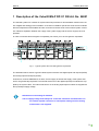
1 Description of the Cube20 BN-P DP-V1 DI8 Art. No. 56001
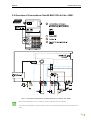
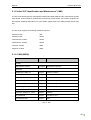
The Cube20 system is a modular I/O system with IP20 protection for decentralized collection and control of digital and analog process variables. It consists of a fieldbus specific bus node and I/O modules
that are independent of the fieldbus and are connected to the bus node via an internal system connection. Galvanic separation between the supply of the system supply and the sensor supply has to be
provided.
In order to maximize electromagnetic compatibility, we advise you to ensure galvanic separation.
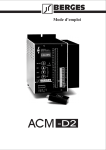
Fig. 1: Typical system structure with galvanic separation
The illustration above shows a typical Cube20 system structure with digital inputs and outputs (DI/DO)
and analog inputs and outputs (AI/AO).
Furthermore, it shows PROFIBUS, I/O area, and I/O supply as well as the supply of the system electronics are galvanically separated. The internal electronics of the digital input/output modules are supplied by the system cable. The internal electronics of the analog input/output modules are supplied via
the input/output supply voltage.
Information on the analog I/O modules.
The I/O supply voltage must always be connected, otherwise communication via
the internal system connection is interrupted, starting from the analog
module that is not supplied.
9
Manual
Cube20 | BN-P DI8
Application Notes
The bus node "Cube20 BN-P DP-V1 DI8" described here is the successor to the
"Cube20 BN-P DI8" that also bears Article Number 56001. Install the GDS
file MUR20B3D.* in order to obtain full functionality. The file can also be
used in existing systems as a substitute for the "Cube20 BN-P DI8" with
GSD file MURR0B3D.*. In this case, the extended functions of the Cube20
BN-P DP-V1 DI8 are not available.
2 Installation
2.1 Mounting
For general information on mounting, please see the Cube20 system manual Art.
No. 56030.
10
Manual
Cube20 | BN-P DI8
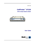
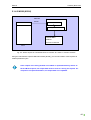
2.2 Overview of Connections Cube20 BN-P DI8 Art. No. 56001
Fig. 2: Overview of Connections Cube20 BN-P DP-V1 DI8 Art. No. 56001
We recommend use of our common terminal block Art. No. 56109.
For further information, please refer to the common terminal block instruction manual.
11
Manual
Cube20 | BN-P DI8
3 Startup
3.1 Terminating PROFIBUS Segments
A terminating resistor is required at the beginning and at the end of the PROFIBUS segment. The
terminating resistors must be powered in order to guarantee a physically clean signal level. A maximum of 16 users may be connected to the PROFIBUS segment.
3.2 Assigning and Setting the PROFIBUS Address
The PROFIBUS address is set by means of two rotary switches directly on the Cube20. Values are
permitted between 0 and 99. Usually, a DP Master assigns the addresses 0 to 2. Therefore, we recommend setting the addresses for Cube20 starting with address 3.
The address setting is read in once after the power supply is connected. A change
of address only becomes effective, therefore, when the module power supply is
reset. When the address is assigned, make sure you provide each PROFIBUS device with a unique individual address.
3.3 GSD File
The equipment described in this manual requires a GSD file
MURR20B3D.* or MURR0B3D.* in order to be operable.
The file suffix indicates the language version. GSD files are available in six different languages.
Language
File Suffix
Language
File Suffix
Default = English
*.gsd
French
*.gsf
English
*.gse
Italian
*.gsi
German
*.gsg
Portuguese
*.gsp
Spanish
*.gss
Tab. 1: GSD File Suffixes
The GSD file is downloadable from the Murrelektronik website:
http://www.murrelektronik.com/
12
Manual
Cube20 | BN-P DI8
The software features described in this manual can only be activated by installing
GDS (DDB) file MUR20B3D.* Version 2.0 or higher.
Compatibility Data
If the bus node "Cube20 BN-P DP-V1 DI8" is operated with GDS file MUR20B3D.*, it
is not replaceable by predecessor model "Cube20 BN-P DI8".
The predecessor model "Cube20 BN-P DI8" is replaceable by bus node "Cube20
BN-P DP-V1 DI8", provided GDS file MURR0B3D.* is used.
3.4 Baud Rates
All devices in a PROFIBUS network operate at a standard baud rate that is defaulted by the bus master. The Cube20 bus node automatically identifies the preset baud rate. Comply with the maximum
permissible line lengths dependent on the baud rate used as shown in the table below. The values
refer to one segment in each case. Larger network topologies are implementable across several segments by means of repeaters.
Maximum Permissible Line Lengths in a PROFIBUS Segment
Transmission speed
in Kbps
9,6
19,2
45,45
93,75
187,5
500
1500
3000
6000
12000
Cable
length
in m
1200
1200
1200
1200
1000
400
200
100
100
100
Tab. 2: Cable lengths in a PROFIBUS segment
13
Manual
Cube20 | BN-P DI8
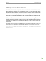
3.5 Configuration and Parameterization
The Cube20 system is usually configured with the help of a configuration tool provided by the master
device manufacturer. The master sends the configuration telegram to the slave during system startup
and defines the number of input and output bytes. Cube20 uses the special identifier format according
to IED 61158. Cube20 can only be operated with DP masters that support the special identifier format.
On the basis of this information, the Cube20 bus node checks the installation for compliance with the
projected configuration. If the bus node detects a difference between the nominal configuration transferred by the DP Master and the physical configuration, the bus node reports a configuration error
message (parameter error message) and does not exchange data with the DP Master. A configuration
or parameter error is displayed at the bus node by the LED "CFg F". If there is a failure, the LED "Cfg
F" lights up red.
The Cube20 system is configured as a modular system. If supported by your DP master, the bus node
"56001 BN-P DP-V1" is automatically added when the Cube20 bus node is entered. The bus node
"56001 BN-P DP-V1" is always the 1st module in the configuration. It is capable of running without any
expansion modules.
14
Manual
Cube20 | BN-P DI8
3.5.1 Example :Configuration of a Cube20 system with Simatic
®
Step7
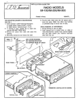
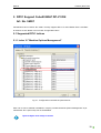
When GSD file MUR20B3D.* is used, the hardware catalog of the Simatic Manager lists Cube20
BN-P DP-V1 DI8 Art. No.: 56001 under "Other Field Devices" and under "I/O" with the name
"Cube20 BN-P DP-V1".
Fig. 3: Cube20 BN-P DP-V1 DI8 Art.No.: 56001 in the Simatic Manager
15
Manual
Cube20 | BN-P DI8
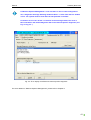
Mark "Cube20 BN-P DP-V1 DI8 Art. No. 56001" and drag the entry to the PROFIBUS string while
keeping the left mouse button depressed, or double-click on the PROFIBUS string. This automatically adds the module "Cube20 BN-P DP-V1 DI8 Art. No.: 56001". In order to add additional
modules to the configuration (max. 15), double-click on the corresponding entry in the hardware catalog.
Fig. 4: Adding Cube20 field units to the Simatic Manager
16
Manual
Cube20 | BN-P DI8
Double-click on any module to open a list box containing the parameter settings for this module.
Select the settings you require.
Fig. 5: Settings of Cube20 field units in the Simatic Manager
17
Manual
Cube20 | BN-P DI8
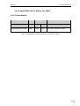
3.5.2 Cube20 BN-P DP-V1 DI8 Art. No. 56001
3.5.2.1 Identification
Description
Art. No.
Cube20 BN-P DP-V1 DI8
56001
Process data
Input
Output
1 byte
0 byte
Identification
0x43, 0x00, 0xDA,0xC1, 0x08
Tab. 3: Identification of Cube20 BN-P DP-V1 DI8 Art. No. 56001
18
Manual
Cube20 | BN-P DI8
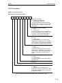
3.5.2.2 Parameters
Number of parameter bytes: 6
Bit assignment of parameter Byte 0
7
6
5
4
3
2
1
0
Diagnostic messages
0 = Enable global diagnostic
1 = Disable global diagnostic
This defines whether the diagnostics are
reported or not. In Setting 1 "Do not report",
the diagnostics of expansion modules are
not reported.
ID-related diagnostic messages*
0 = report
1 = do not report
This defines whether the ID-related diagnostics are reported or not. In Setting 1 "Do
not report", the ID-related diagnostics of
expansion modules are not reported.
Module status diagnostic messages*
0 = report
1 = do not report
This defines whether the module-status
diagnostics are reported or not. In Setting 1
"Do not report", the module status diagnostics of expansion modules are not reported.
Channel-related diagnostic messages*
0 = report
1 = do not report
This defines whether the channel-related
diagnostics are reported or not. In Setting 1
"Do not report", the channel-related diagnostics of expansion modules are not reported.
US node undervoltage*
0 = report
1 = do not report
This defines whether a US undervoltage is
reported or not.
Reserved
Reserved
Configuration test*
0 = Default
1 = "Machine Options Management"
Define here whether you want to use "Machine Options Management" or retain the
default configuration.
Fig. 6: Parameter Byte 0 of Cube20 BN-P DP-V1 DI8 Art. No. 56001
19
Manual
Cube20 | BN-P DI8
Bit assignment of parameter Byte 1
Reserved
Bit assignment of parameter Byte 2
This defines whether actuator power supply diagnostics, such as undervoltage, or no voltage, are
reported for the assigned slot or not.
0 = report
1 = do not report
Byte 2
7
6
Diagnostic Settings
5
4
3
2
1
0
Actuator power supply diagnostic for Slot
0 (Reserved)
Actuator power supply diagnostic Slot 2*
Actuator power supply diagnostic Slot 3*
Actuator power supply diagnostic Slot 4*
Actuator power supply diagnostic Slot 5*
Actuator power supply diagnostic Slot 6*
Actuator power supply diagnostic Slot 7*
Actuator power supply diagnostic Slot 8*
Fig. 7: Parameter Byte 2 of Cube20 BN-P DP-V1 DI8 Art. No. 56001
20
Manual
Cube20 | BN-P DI8
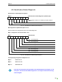
Bit assignment of parameter bytes 3 to 5
This defines whether actuator power supply diagnostics, such as undervoltage, or no voltage, are
reported for the assigned slot or not.
0 = report
1 = do not report
Byte 3: Actuator power supply diagnostic for Slots 9 to 16
Byte 3
7
6
Diagnostic Settings
5
4
3
2
1
0
Actuator power supply diagnostic Slot 9*
Actuator power supply diagnostic Slot 10*
Actuator power supply diagnostic Slot 11*
Actuator power supply diagnostic Slot 12*
Actuator power supply diagnostic Slot 13*
Actuator power supply diagnostic Slot 14*
Actuator power supply diagnostic Slot 15*
Actuator power supply diagnostic Slot 16*
Fig. 8: Parameter Byte 3 of Cube20 BN-P DP-V1 DI8 Art. No. 56001
Corresponding assignment of Bytes 4 and 5:
Byte 4:
Actuator power supply diagnostic for Slots 17 to 24*
Byte 5:
Actuator power supply diagnostic for Slots 25 to 32*
* only when GSD file MUR20B3D.* is used
3.5.3 Cube20/67 Interface, Art. No. 56140
When the GDS file MUR20B3D.* is used, you also have the interface module "56140 Cube20/67 Interface" and several Cube67 modules at your disposal, besides the previous Cube20 modules available.
Use of the interface module "56140 Cube20/67 Interface" before replacing a Cube20 module by a
Cube67 module is optional, i.e. you are free to change directly from Cube20 to Cube67 (as in Fig. 9:
56221 after 56701), or to configure the interface module "56140 Cube20/67 Interface" (Fig. 10: ). The
two configurations are valid.
21
Manual
Cube20 | BN-P DI8
Fig. 9: Configuration with Cube20 and Cube67 modules without interface module
Fig. 10: Configuration with Cube20 and Cube67 modules with interface module
The configuration of a Cube20/Cube67 System may only include one interface
module "56140 Cube20/67 Interface".
3.5.4 Modules and Slots
Number of available slots
32*
Max. number of usable modules
16
(including bus nodes Cube20 BN-P DP-V1 DI8 Art. No.
56001, including interface module "56140 Cube20/67 Interface")*
* only when GSD file MUR20B3D.* is used
Too many modules are configured in the configuration in Fig. 11: . Since module 56140 "Cube20/67
Interface" is not considered in the calculation of the maximum number of modules, the error message
"Slot 18: False Module" is issued, even if this configuration physically exists.
22
Manual
Cube20 | BN-P DI8
Fig. 11: Example of an incorrect configuration
Please note that the number of modules to be configured may be reduced if you deploy Cube67+
modules. For example, it is not possible to use more than six modules of type Cube67+ DIO12 IOL4 E
8xM12 Art. No. 56752, as they require five slots each: one slot for the module itself and four slots for
virtual modules.
23
Manual
Cube20 | BN-P DI8
Fig. 12: Example of a configuration using Cube67+ modules
3.6 I/O - Data Cube20 BN-P DP-V1 DI8 Art. No. 56001
Bit assignment I/O data - input data PAE
Byte 0
Bit
7
6
5
4
3
2
1
0
Terminal
X2 03
X2 02
X2 01
X2 00
X1 03
X1 02
X1 01
X1 00
Tab. 4: Input Data Cube20 BN-P DP-V1 DI8 Art. No. 56001
24
Manual
Cube20 | BN-P DI8
4 Diagnostics
4.1 LED Indicators
For a detailed description, please see the Cube20 System Manual Art. No. 56030.
4.1.1 Significance of the States of the "Bus Run" LED
The "Bus Run" LED represents the state of PROFIBUS communication on the
Cube20 BN-P DI8 Art. No. 56001.
Fig. 13: Bus-Run LED of Cube20 BN-P DI8 Art. No. 56001
LED Display
Response
State
Lights up continuously
PROFIBUS-DP data exchange
Flashing
(green)
No PROFIBUS-DP data exchange
Off
- PROFIBUS firmware not yet initialized
- Voltage at terminal UB too low (<13V)
Tab. 5: LED-Bus-Run on Cube20 BN-P DP-V1 DI8 Art. No.: 56001
25
Manual
Cube20 | BN-P DI8
4.1.2 Significance of the States of the "Cfg F" LED
The "Cfg F" LED represents the state of a correct/incorrect configuration on the
Cube20+ BN-P DP-V1 DI8 Art. No. 56001.
Fig. 14: Cfg F-LED on Cube20 BN-P DP-V1 DI8 Art. No. 56001
LED Display
Response
State
Lights up continuously
(red)
Real configuration does not match the projected
configuration
Off
Configuration correct
Tab. 6: Cfg F-LED on the Cube20 BN-P DP-V1 DI8 Art. No. 56001
26
Manual
Cube20 | BN-P DI8
4.1.3 Displays for the Supply Voltage at the Terminals
Please see the Cube20 System Manual Art. No. 56030.
4.1.4 Diagnostics Overview
Overview of the reported diagnostic messages Cube20 BN-P DP-V1 DI8 Art. No.: 56001
Designation of
terminals
Description
Fieldbus Diagnostics
Related to:
UB
Undervoltage
(< 18V)
Undervoltage
Modules
UI
Undervoltage
(< 18V)
Undervoltage
Modules
US
Overload or shortcircuit sensor supply
Short-circuit
Modules
Tab. 7: Overview of reported diagnostic messages
27
Manual
Cube20 | BN-P DI8
4.2 Diagnostics via the Fieldbus
There are a total of four levels of diagnostic information over PROFIBUS on the Cube20.
1. ProfiBus standard diagnostics
Bytes 0 to 5 of diagnostic telegram.
2. Identification-related diagnostic (information about what modules have a diagnostic function)
Bytes 6 to 10
Parameter Byte 0, Bit 1 = 0 (ID-related diagnostic is activated)
3. Module status diagnostic (information about what modules have a diagnostic function, or
are missing, or are incorrect).
Bytes 11 to 22 Parameter Byte 0, Bit 2 = 0 (module status diagnostic is activated)
4. Channel-related diagnostic (short-circuits at outputs, etc.).
Byte 23….
Parameter Byte 0, Bit 1 = 0, Bit 2 = 0 (ID-related and module status diagnostics are
switched on) 3 byte per channel, max. 64 channel diagnostics.
When you set the bus node parameter "Diagnostic Message" to "Disable global
diagnostics", the blocks "ID-related diagnostic" and "Module status diagnostic"
still exist, but the content of these diagnostic blocks always indicate an errorfree
state.
Use of the Profibus DP-V1 functionality Alarms and Status Reports for the diagnostic is not supported by Cube20 BN-P DP-V1 DI8 Art. No. 56001. Select Mode
DP-V0 for the DP Alarm Mode (diagnostic mode) if the Profibus Master configuration tool offers an option.
All diagnostic messages are reported slot-dependent. Note here that some configuration tools name the first slot as Slot 0; others name it Slot 1. The reported
diagnostic messages refer to the numbering of the first slot with "Slot 1".
28
Manual
Cube20 | BN-P DI8
4.2.1 Standard Diagnostic Information Format
Standard diagnostic information Byte 0 to 5
Byte 0
7
6
5
4
3
2
1
0
Diag.station_non_existent
This bit is set by the DP master if this DP slave is not
accessible (to generate a group diagnostic). The DP
slave sets this bit to zero.
Diag.station_not_ready
This bit is set by the DP slave, if the SP slave is not
ready for data exchange.
Diag.cfg_Fault
This bit is set by the DP slave when the configuration
data previously received from the master does not
match the configuration data detected by the DP
slave..
Diag.ext_diag
This bit indicates that a diagnostic entry is present in
the slave-specific diagnostic area (Ext_Diag_Data).
Diag.not supported
This bit is set by the DP slave as soon as a function
not supported by the DP slave is requested.
Diag. Invalid slave response
This bit is set by the DP master when an implausible
response is received from an addressed DP slave.
The DP slave sets this bit to zero.
Diag.prm_fault
This bit is set by the DP slave if the previous parameter telegram was erroneous, e.g. incorrect length, incorrect ID number, invalid parameter.
Diag.master_lock
The DP slave was parameterized by another master.
This bit is set by the master, if the address in Byte 3 is
not equal to Ffhex and is not equal to the slave's own
address. The DP slave sets this bit to zero.
Fig. 15: Standard diagnostic information Byte 0
29
Manual
Cube20 | BN-P DI8
Byte 1
7
6
5
4
3
2
1
0
Diag.Prm_req
If the DP slave sets this bit, it must be reparameterized and reconfigured. This bit remains set until reparameterization is completed.
Diag.Stat_diag
If the DP slave sets this bit, the DP master must collect diagnostic data until this bit is deleted. The DP
slave sets this bit, if it can not provide valid utility data,
for instance.
set to 1
Diag.WD_ON
If this bit is set to 1, the watchdog timer is activated.
Diag.freeze_mode
This bit is set by the DP slave when it receives the
Freeze command.
Sync_mode
This bit is set by the DP slave when it receives the
Sync command.
Diag.Not_Present
This bit is set by the DP master for the DP slaves not
contained in the master parameter block. The DP
slave sets this bit to zero.
Diag.deactivated
This bit is set by the DP master when the DP slave is
removed from the master parameter block of the DP
master. The DP slave always sets this bit to zero.
Fig. 16: Standard diagnostic information Byte 1
30
Manual
Cube20 | BN-P DI8
Byte 2
7
6
5
4
3
2
1
0
Reserved
Diag.ext_overflow
If this bit is set, there is more diagnostic information
available than is specified in Ext_Diag_Data. For example, the DP slave sets this bit when there is more
channel diagnostic information available than the DP
slave can enter into its send buffer. The DP master
sets this bit when the DP slave sends more diagnostic
information than the DP master can take into account
in its diagnostic buffer.
Fig. 17: Standard diagnostic information Byte 2
Byte 3
7
6
5
4
3
2
1
0
Diag.master_add
The address of the DP Master which parameterized
this DP slave is entered in this byte. If the DP slave is
not parameterized by a DP master, the DP slave sets
the address Ffhex in this byte.
Fig. 18: Standard diagnostic information Byte 3
Byte 4
7
6
5
4
3
2
1
0
ID number highbyte
Fig. 19: Standard diagnostic information Byte 4
Byte 5
7
6
5
4
3
2
1
0
ID number lowbyte
Fig. 20: Standard diagnostic information Byte 5
31
Manual
Cube20 | BN-P DI8
4.2.2 Identification-Related Diagnostic
Identification-related diagnostic bytes 6
Byte 6
7
6
Identification-related diagnostic (header byte)
5
4
3
2
1
0
Block length in bytes, incl. header byte (here: 05hex /
05dec)
set to 01
Fig. 21: Identification-related diagnostic Byte 6
Bit assignment of parameter bytes 7 to 10
Defines whether the assigned slot has an ID-related diagnostic.
Byte 7: Diagnostic of the ID for Slots 1 to 8:
Byte 7
7
6
Identification
5
4
3
2
1
0
Slot 1 has diagnostic
Slot 2 has diagnostic
Slot 3 has diagnostic
Slot 4 has diagnostic
Slot 5 has diagnostic
Slot 6 has diagnostic
Slot 7 has diagnostic
Slot 8 has diagnostic
Fig. 22: Identification-related diagnostic Byte 7
Corresponding assignment of Bytes 8 to 10:
Byte 8
Slots 9 to 16
Byte 9
Slots 17 to 24
Byte 10
Slots 25 to 32
If you do not set the bus node parameter "ID-related diagnostic messages" to "Do
not report", the block of ID-related diagnostics is no longer contained in the diagnostic telegram.
32
Manual
Cube20 | BN-P DI8
4.2.3 Module Status Diagnostic
Module status diagnostic Bytes 11 to 22
Byte 11
7
6
Module Status Diagnostic (Header Byte)
5
4
3
2
1
0
Block length in bytes, incl. header byte (here: 0Chex /
12dec)
Set to 00
Fig. 23: Module status diagnostic Byte 11
Byte 12
7
6
Module Status Type
5
4
3
2
1
0
Unused
Set to 1 for module status
Unused
Unused
Unused
Unused
Unused
Set to 1 for status block
Fig. 24: Module status diagnostic Byte 12
Byte 13
7
6
Slot Number
5
4
3
2
1
0
Set to 0 since all diagnostics are reported to the bus node
slot.
Fig. 25: Module status diagnostic Byte 13
Byte 14
7
6
Status Specification
5
4
3
2
1
0
Set to 0 since it is not further differentiated.
Fig. 26: Module status diagnostic Byte 14
33
Manual
Cube20 | BN-P DI8
Byte 15
7
6
Status Report
5
4
3
2
1
0
Slot 1
Possible bit combinations:
Slot 2
00 Valid data, no error
01 Invalid data, error
10 Incorrect module
11 Missing module
Slot 3
Slot 4
Fig. 27: Module status diagnostic Byte 15
Corresponding assignment of Bytes 16 to 22:
Byte 16:
Diagnostic of module status for Slots 5 to 8
Byte 17:
Diagnostic of module status for Slots 9 to 12
Byte 18:
Diagnostic of module status for Slots 13 to 16
Byte 19:
Diagnostic of module status for Slots 17 to 20
Byte 20:
Diagnostic of module status for Slots 21 to 24
Byte 21:
Diagnostic of module status for Slots 25 to 28
Byte 22:
Diagnostic of module status for Slots 29 to 32
If you do not set the bus node parameter "Module status diagnostic messages" to
"Do not report", the block of module status diagnostics is no longer contained in
the diagnostic telegram.
34
Manual
Cube20 | BN-P DI8
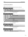
4.2.4 Channel-Related Diagnostic
Channel-related diagnostic Bytes 23 to 25 and following
Three bytes are assigned in the diagnostic telegram for each channel-related diagnostic. If, for example, 5 channel-related diagnostics are available, a total of 5 times 3 bytes channel-related diagnostic
information will follow from byte 23.
Byte 23
7
6
ID number
5
4
3
2
1
0
ID numbers 0 to 63
set to 10
Fig. 28: Channel-related diagnostic Byte 23
Byte 24
7
6
Channel Number
5
4
3
2
1
0
Channel numbers 0 to 63
Cube20:
00 to 07 (X0)
10 to 17 (X1)
20 to 27 (X2)
30 to 37 (X3)
Input/output
00 = reserved
01 = input
10 = output
11 = input/output
Fig. 29: Channel-related diagnostic Byte 24
35
Manual
Cube20 | BN-P DI8
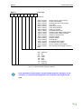
Byte 25
7
6
Fault Type
5
4
3
2
1
0
Fault type
01hex
02hex
04hex
06hex
07hex
08hex
09hex
10hex
11hex
13hex
15hex
17hex
18hex
1Ahex
1Bhex
1Chex
1Dhex
1Ehex
tage
(01dec)
(02dec)
(04dec)
(06dec)
(07dec)
(08dec)
(09dec)
(16dec)
(17dec)
(19dec)
(21dec)
(23dec)
(24dec)
(26dec)
(27dec)
(28dec)
(29dec)
(30dec)
Short circuit (in sensor supply)
I/O link undervoltage
Overload (sensor power supply)
Line break
Upper limit overshot
Lower limit undershot
Fault (e.g. I/O link)
Parameterization error
Actuator power supply undervoltage
Actuator power supply overload
Reference channel error
Actuator warning
Actuator disable
External fault
No actuator power supply
No sensor power supply
No ext. actuator power supply
Ext. actuator power supply undervol-
Channel type
000 = reserved
001 = bit
010 = 2 bits
011 = 4 bits
100 = byte
101 = word
110 = 2 words
111 = reserved
Fig. 30: Channel-related diagnostic Byte 25
If you set the bus node parameter "channel-related diagnostic messages" to "Do
not report", no channel-related diagnostics are contained in the diagnostic telegram.
36
Manual
Cube20 | BN-P DI8
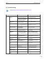
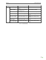
4.3 Troubleshooting
Rectify errors or incorrect modules in ascending slot order.
Diagnostic Message
Possible Cause
Action
Chan-
Overload or short-circuit of
sensor power supply to 0V.
Change cable to sensor or check
sensor for short-circuit.
Overload or short-circuit of
internal system connection
(channel type = 000)
Check cables on associated line.
Undervoltage
I/O link
I/O link undervoltage (events
0x5100 to x5119)
Check cable to sensor.
Overload
Current load on a line greater
than 4 A and less than 4.4 A
(100 to 110%)
Check current load and possibly
distribute to other lines.
I/O link overload
I/O link overload
(event 0x5410)
Check current load.
Line break
Defective line. Only for analog inputs and outputs.
Check connection to sensor or
sensor itself.
Line break
I/O link
I/O link device not plugged in
or incorrect (invalid data
length, cycle time too short,
etc.)
Check connection to I/O link
device. Check data length. Increase cycle time in parameters.
Upper limit overshot
Analog input measuring
range overshot.
Check connection to sensor or
sensor itself.
Upper limit overshot
(I/O link)
IO link event 0x8C10,
0x8C20
Check parameterization or measuring range.
Lower limit undershot
Analog input measuring
range undershot
Check connection to sensor or
sensor itself.
Lower limit undershot
(I/O link)
I/O link event 0x8C30
Check parameterization or measuring range.
Fault
I/O link fault not assignable to
another fault
Check I/O link devices or read
out their event memories.
Parameterization
error
Parameterization incorrect.
Check parameterization.
Actuator power
supply undervoltage
Actuator power supply < 18 V
Check power supply unit and
cable.
Reference channel
fault
TH module KTY not plugged
in
Install KTY correctly.
nel
Short-circuit (sensor
supply)
37
Manual
Cube20 | BN-P DI8
Diagnostic Message
Possible Cause
Action
Actuator warning
External power supply to an
output.
Check cable.
Actuator disable
Overload or short-circuit of
output signal to 0V.
Check wiring or actuator.
External fault
Desina diagnostic
Check sensor or wiring.
No actuator supply
Actuator power supply < 13 V
Check power supply unit and
cable.
No sensor voltage
Sensor power supply < 13 V
Check power supply unit and
cable.
No ext. actuator
power supply
External
actuator power supply < 13 V
Check power supply unit and
cable.
Ext. actuator power
supply undervoltage
Ext. actuator power supply <
18 V
Check power supply unit and
cable.
Tab. 8: Troubleshooting
38
Manual
Cube20 | BN-P DI8
5 DPV1 Support Cube20 BN-P DP-V1 DI8
Art. No. 56001
Cube20 BN-P DP-V1 DI8 Art. No. 56001 currently supports DP-V1 for each Master Class 1 and Master Class 2 access. Below is an overview of supported indices.
5.1 Supported DPV1 Indices
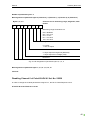
5.1.1 Index 10 "Machine Options Management"
Fig. 31: Configuration test within the parameter list
Slots 2 to 32 can be enabled or disabled in 4 bytes, provided "Machine Options Management" is parameterized. Slot 1 (bus node) can not be disabled.
Byte0 to Byte3 must always be written
39
Manual
Cube20 | BN-P DI8
Byte 0 Disable Slots 1 to 8:
Byte 0
7
6
5
4
3
2
1
0
Reserved
0 = Slot 2 enabled
1 = Slot 2 disabled
0 = Slot 3 enabled
1 = Slot 3 disabled
0 = Slot 4 enabled
1 = Slot 4 disabled
0 = Slot 5 enabled
1 = Slot 5 disabled
0 = Slot 6 enabled
1 = Slot 6 disabled
0 = Slot 7 enabled
1 = Slot 7 disabled
0 = Slot 8 enabled
1 = Slot 8 disabled
Fig. 32: Assignment of Byte 0
Corresponds to:
Byte 1: Disable Slots 9 to 16:
Byte 2: Disable Slots 17 to 24:
Byte 3: Disable Slots 25 to 32:
Placeholders may not be disabled If an attempt is made to do this, a configuration error is displayed.
Read/write requests in "Default Configuration" receive the negative reply "Feature not supported".
Read requests with "Machine Options Management" receive a positive reply. The response contains
the parameters that were previously written with Index 10.
If the configuration is invalid, Index 10 write requests always receive a positive reply. If the configuration is valid after an Index 10 write request, every following Index 10 write request receives a negative
reply with "State conflict".
If no valid configuration is set in "Machine Options Management", no "Static diagnostic" can be set in
the system.
40
Manual
Cube20 | BN-P DI8
If "Machine Options Management" is set and there is still no valid configuration
set, a diagnostic message "Missing module at Slot 1" is sent if the link to a module
is lost. The system most be reset after the link problem is rectified.
If a further error occurs at Slot 1 in relation to the missing module, this error is
NOT indicated in the default diagnostic but in the channel-specific diagnostic (see
Fig. 33: Fig. 33: ).
Fig. 33: Error display in default and channel-specific diagnostic
For more details on "Machine Options Management", please refer to Chapter 6.
41
Manual
Cube20 | BN-P DI8
5.1.2 Index 12 "BusControl"
Byte 0 "BusControl":
Byte 0
7
6
5
4
3
2
1
0
0 = no software reset netX
1 = software reset netX
unassigned
Fig. 34: BusControl byte DPV1 Index 12
Use the BusControl request to perform a bus node reset from the PLC.
5.1.3 Index 13 "Machine Options Management Configuration Test"
Byte 0 Configuration test:
Byte 0
7
6
5
4
3
2
1
0
0=
1=
Configuration test failed
or
System not "OPERATIONAL"
Configuration test successful
AND
System "OPERATIONAL"
unassigned
Fig. 35: Assignment of configuration test
Read request must be set with Index 13 to know whether a valid configuration was set in "Machine
Options Management". Here, 1 is returned if the configuration is valid and the system is "OPERATIONAL", otherwise 0.
If the bus node is parameterized with "Default configuration"; the negative reply "Feature not supported" is sent.
Write requests receive a negative reply "Feature not supported".
42
Manual
Cube20 | BN-P DI8
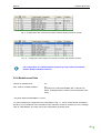
5.1.4 Index 255 "Identification and Maintenance" (I&M)
The bus node itself supports a read request to I&M Index 65000 (IM0) and the manufacturer-specific
Index 65100. If other Cube67+ modules are connected to the bus nodes, the Cube67+ modules can
then support additional I&M indices. For more details, please refer to the related module documentation.
The bus node supports the following read/write requests:
Read bus node
IM0
Read bus node
IM100
Write Not-IOL module
IM100
Read Not-IOL module
IM100
Write IOL module
IM98
Read IOL module
IM98
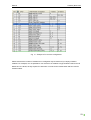
5.1.4.1 IM0 (65000)
Content
Size
Content
10 bytes
Manufacturer-specific
MANUFACTURER_ID
2 bytes
012Fhex, 303dec
ORDER_ID
20 bytes
'56001
SERIAL_NUMBER
16 bytes
'
HARDWARE_REVISION
2 bytes
Manufacturer-specific
SOFTWARE_REVISION
4 bytes
Manufacturer-specific
REVISION_COUNTER
2 bytes
Manufacturer-specific
PROFILE_ID
2 bytes
F600hex
PROFILE_SPECIFIC_TYPE
2 bytes
0003hex
IM_VERSION
2 bytes
0101hex for V1.1
IM_SUPPORTED
2 bytes
0hex
Header
Manufacturer-specific
I&M data
'
'
Tab. 9: IM0
43
Manual
Cube20 | BN-P DI8
5.1.4.2 IM100 (65100)
I&M Call
Index 255
65100
BN-P:
I&M
int. system link
Cube20 BN-P
Module:
Access via internal
Slot x
Fig. 36: IM100 request to Cube20 BN-P DP-V1 DI8 Art. No. 56001 or Cube67 modules
Using the manufacturer-specific I&M Index 65100 (IM100), you can send read or write requests to
module parameter bytes.
If the outputs of an analog module are enabled or reparameterized by means of
DP-V1 IM100 requests, the output data must be reset to 0 during the request. On
completion of reparameterization, the output data are re-updated.
44
Manual
Cube20 | BN-P DI8
Example:
In the simple example below, we will show you how to disable a channel of an analog output module
using two IM100 requests and enable another channel of the same module to switch a sensor off and
switch another sensor on. The example was carried out using a Siemens controller. DP-V1 requests
were handled using module that are available in the download section of the Murrelektronik website.
The configuration:
Fig. 37: Configuration example
Channel 0 of Cube20 module AO4 U/I Art. No. 56220 is enabled for the range 4 to 20 mA; here are
the parameters in detail:
Fig. 38: Example of parameters
The current he parameter string of the module is 03 00 00 00 00 00 00 00 00 00 00 00; this can also
be found in the parameter assignment of Cube20 AO4 U/I Art. No. 56220 (extract from the Cube20
Expansion Manual (Art. No. 56035):
45
Manual
Cube20 | BN-P DI8
Number of parameter bytes: 12
Bit assignment of parameter bytes 0 (Channel 0), 3 (Channel 1), 6 (Channel 2), 9 (Channel 3)
Bytes 0, 3, 6, 9
7
6
5
Channels 0 to 3: measuring range, diagnostic, data
format
4
3
2
1
0
Measuring range Channels 0 to 3
000 = disabled
001 = 0 to 10 V
010 = ± 10 V
011 = 4 to 20 V
100 = 0 to 20 V
Diagnostics
0 = report
1 = do not report
Data Format
0 = Byte sequence High/Low (Motorola)
1 = Byte sequence Low/High (Intel)
Reserved
Fig. 39: Bit assignment of parameter bytes 0, 3, 6, 9
Bit assignment of parameter bytes 1, 2, 4, 5. 7, 8, 10, 11:
reserved
Disabling Channel 0 of Cube20 AO4 U/I Art. No. 56220
In order to change the module parameters using DP-V1, the DP-V1 Write Request is sent:
5F 02 FF 08 08 00 FE 4C A0 01 01 00
46
Manual
Cube20 | BN-P DI8
Meaning of the characters in detail (all hexadecimal):
5F
Write Request
02
Slot Number
FF
Number of index used (255dec = IM)
08
Number of useful data in bytes
08
Call Function
00
Reserved
FE 4C
(65100 dec) = IM100
A0 01
Index 20 01, here the highest bit is set (2+8 = A), it means write request
01
The 1st parameter byte (parameter byte 0) is handled
00
Write parameter for the selected byte
Read Request
After the write request, a reply telegram is sent containing the written data length. According to the IM
standard, this must be followed by a read request (without parameters).
5E 02 FF F0
Meaning of the numerals in detail (all hexadecimal):
5E
Read Request
02
Slot Number
FF
Number of index used (255dec = IM)
F0
Number of useful data in bytes
The parameter change was successful, Channel 0 is now set to "disabled".
47
Manual
Cube20 | BN-P DI8
Enabling Channel 1 for the range 4 to 20 mA
The value 3 (binary 0000 0011) must be set for parameter byte 3. Here are the telegram data in detail:
5F 02 FF 08 08 00 FE 4C A0 01 04 03
Meaning of the numerals in detail (all hexadecimal):
5F
Write Request
02
Slot Number
FF
Number of index used (255dec = IM)
08
Number of useful data in bytes
08
Call Function
00
Reserved
FE 4C
(65100 dec) = IM100
A0 01
Index 20 01, here the highest bit is set (2+8 = A), it means write request
04
The 4th parameter byte (parameter byte 3) is handled
03
Write parameter for the selected byte
According to the IM standard, this must be followed by a read request (without parameters).
The parameter change was successful; Channel 1 is not enabled for the range 4 to 20 mA.
STEP7 libraries that contain modules for IM accesses are available in the download
section of the Murrelektronik website:
www.murrelektronik.com
48
Manual
Cube20 | BN-P DI8
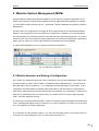
6 Machine Options Management (MOM)
Using the Machine Options Management ("MOM"), you can perform a module configuration on machines. If the machine comprises a Basic Module A and an optional Machine Module B, for example,
you can disable modules belonging to the – nonexistent – Machine Module B using Machine Options
Management.
For this reason, the configuration tool configures all the optional modules of the Machine Module B
modules. This configuration is then the "Maximum configuration". In addition, you can parameterize
the "Configuration test" parameter of the bus node with "Machine Options Management". The system
reports no error after runup and this is totally independent of the received configuration or parameterization. The bus node then reverts to data exchange, but the data are not yet updated.
In order to illustrate MOM, here is an example of maximum configuration:
Fig. 40: Maximal configuration
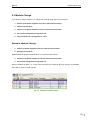
6.1 Module Selection and Setting a Configuration
If the system is in data exchange mode, set the configuration you require by disabling the slots of the
unused modules by means of DP-V1 Index 10 ("Machine Options Management"). You will find a detailed description of this in Section 5.1.1. A configuration text then takes place in the system, i.e. the
configuration set using MOM is compared to the actual setup. If this test is OK, the configuration is
valid and the system reverts to data exchange mode. If the test fails, the configuration is invalid and a
diagnostic is generated (missing or false module). The system is then no longer in data exchange
mode - the static diagnostic bit is set.
The test result can be requested using DP-V1 Index 13 ("Machine Options Management Configuration
Test"). A detailed description of this is in Section 5.1.3. If the configuration is invalid, you can continue
to try using MOM to set a valid configuration.
In our example, only the modules in Slots 1, 2, 4 and 5 are physically present. The module in Slot 3 is
not present. It is then disabled by a DP-V1 write request using Index 10.
49
Manual
Cube20 | BN-P DI8
Fig. 41: Example of an invalid configuration
The physical setup does not comprise the module highlighted by the red border (Slot 3).
Telegram parameters in detail:
5F 00 0A 04 04 00 00 00
Meaning of the numerals in detail (all hexadecimal):
5F
Write Request
00
Slot number (Slot 1)
0
A
Number of index used (10dec)
04
Number of useful data in bytes
04
1st parameter byte (parameter byte 0)
00
2nd parameter byte (parameter byte 1)
00
3rd parameter byte (parameter byte 2)
00
4th parameter byte (parameter byte 3)
Bit pattern of parameter bytes:
Byte 1:
Bit value:
0
0
0
0
0
1
0
0 Æ Hex: 04
Slot number:
8
7
6
5
4
3
2
1
Bit value:
0
0
0
0
0
0
0
0 Æ Hex: 00
Slot number:
16
15
14
13
12
11
10
9
Byte 2:
Byte 3 and Byte 4 are also 0, as is Byte 2.
50
Manual
Cube20 | BN-P DI8
A write request receives a positive reply telegram if it was successful, irrespective
of the fact whether the configuration is valid or not.
6.2 Configuration Test
A DP-V1 read request with Index13 can test whether the configuration is valid.
Telegram parameters in detail:
5E 00 0D 01
Meaning of the numerals in detail (all hexadecimal):
5E
Read Request
00
Slot Number
0D
Number of index used (13dec)
01
Number of useful data in bytes
If "Machine Options Management" is a default configuration, this results in a positive reply telegram
that looks like this:
5E 00 0D 01 01 (configuration is valid and system is OPERATIONAL) or 5E 00 0D 01 00 (otherwise).
If the configuration is valid, the system reverts to data exchange mode. If there are diagnostics
present, they are displayed, provided they were not disabled by bus node parameters.
If the configuration is invalid, the system does not revert to data exchange mode. Instead, the static
diagnostic is set and a slot error is displayed.
Our example shows a valid configuration. The system is in data exchange mode.
If a valid configuration is set, it is not possible to set another configuration using
MOM. If you attempt to do this, it results in a negative reply telegram.
In order to know which parameters were sent by Index 10, a read request can be made to Index 10
which returns the written parameters. If nothing was written, then zeros are returned.
If the bit is set for a slot that does not exist (example: Slots 1 to 9 are assigned and
Mask 00 00 02 00 was set (= Slot 18 is disabled), then this bit is ignored.
51
Manual
Cube20 | BN-P DI8
6.3 Module Change
If you want to change modules, i.e. change the physical setup, this is the procedure:
1. Switch off all power supplies of the bus node and all modules.
2. Replace the modules.
3. Switch on all power supplies of the bus node and all modules.
4. Set a valid configuration using Index 10.
5. Check whether the configuration is valid.
Example: Module Change
1. Switch off power supplies of the bus node and all modules.
2. Replace the modules.
Module 56220 is removed, Module 56221 is set at the same location.
3. Switch on all power supplies of the bus node and all modules.
4. Set a valid configuration using Index 10.
Now the modules of Slots 1, 3, 4, and 5 are connected; the module at Slot 2 is missing. It is disabled
using DP-V1 Index 10 write request.
Fig. 42: Example of module change
52
Manual
Cube20 | BN-P DI8
Telegram parameters in detail:
5F 00 0A 04 02 00 00 00
Meaning of the numerals in detail (all hexadecimal):
5F
Write Request
00
Slot number (Slot 1)
0
A
Number of index used (10dec)
04
Number of useful data in bytes
02
1st parameter byte (parameter byte 0)
00
2nd parameter byte (parameter byte 1)
00
3rd parameter byte (parameter byte 2)
00
4th parameter byte (parameter byte 3)
Bit pattern of 1st parameter byte:
Byte 1:
Bit value:
0
0
0
0
0
1
0
0 Æ Hex: 02
Slot number:
8
7
6
5
4
3
2
1
5. Check whether the configuration is valid.
Now a test can be made using DP-V1 V1 read request by Index13 whether the configuration is valid. If
this is the case, the system is in data exchange mode. The module change was successful.
53
Manual
Cube20 | BN-P DI8
7 Usable Modules
7.1 Cube20 Modules
All Cube20 modules are operable on the Cube20 BN-P DP-V1 DI8.
Please refer to the Cube20 System Manual for lists of the various Cube20 modules.
You will find a list of manuals in the section "List of Manuals and Layout" in this
manual.
7.2 Cube67 Modules
All Cube67 modules are operable on the Cube20 BN-P DP-V1 DI8.
Please refer to the Cube67 System Manual for lists of the various Cube20 modules.
You will find a list of manuals in the section "List of Manuals and Layout" in this
manual.
7.3 Cube67+ Modules
All Cube67+ modules are operable on the Cube20 BN-P DP-V1 DI8. The "+" of the Cube67+ stands
for the expanded functionality of these modules.
Please refer to the Cube67+ Manual for the lists and information on the various
Cube67+ modules.
You will find a list of manuals in the section "List of Manuals and Layout" in this
manual.
54
Manual
Cube20 | BN-P DI8
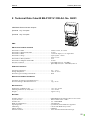
8 Technical Data Cube20 BN-P DP-V1 DI8 Art. No. 56001
PROFIBUS Slave IP20 with 8 inputs
[Terminal X1] Æ 4 inputs
[Terminal X2] Æ 4 inputs
EMC
EN 61131-2 Product standard
EN 61000-4-2 ESD ....................................................................
EN 61000-4-3 RF-Field & GSM ................................................
EN 61000-4-4 Burst ...................................................................
EN 61000-4-5 Surge ..................................................................
....................................................................................................
EN 61000-4-6 HF-asymmetric ..................................................
EN 61000-4-8 Magnetic field 50 Hz .........................................
EN 55011 Emission ....................................................................
....................................................................................................
Contact ± 4 kV, air ± 8 kV
10 V/m
± 2 kV DC inputs, ± 1 kV signal lines
Asym./symm. ± 500 V
Asym. ± 1 kV
10 V
30 A/m
QP 40 dBµV/m (30 - 230 MHz)
QP 47 dBµV/m (230 - 1000 MHz) Class A
Ambient Conditions
Operating temperature ............................................................... 0°C... +55°C
Storage temperature ................................................................... -20°C to +85°C
Enclosure type according to EN 60529 ..................................... IP 20
Mechanical Ambient Conditions
Oscillation according to EN 60068 Part 2-6 ............................... 5 g
Shock according to EN 60068 Part 2-27 .................................... 15 g / 11 ms
Miscellaneous
Dimensions (LxWxH) in mm .................................................... 117 x 56 x 47 mm
Mounting dimension (L xW)in mm ........................................... 117 x 56 mm
Weight ....................................................................................... Approx. 170 g
Bus Data
Transfer protocol ........................................................................
Acyclic services ..........................................................................
Transfer rate................................................................................
Baud rate identification ..............................................................
Operating mode ..........................................................................
Addressing ..................................................................................
Identity number ..........................................................................
Galvanic isolation .......................................................................
PROFIBUS-DP according to IEC 61158 / 61784
DP-V1 Master Class 1 and 2
9,6 - 12000 kBaud
Automatically
Sync-Mode, Freeze-Mode are supported
0 till 99 with BCD-rotary switch
0B3D hex
500 V between Bus and internal Logic
55
Manual
Cube20 | BN-P DI8
System connection
Transfer protocol ........................................................................ Internal system
Addressing .................................................................................. Automatic
Connection Possibilities
Internal system connection Out ..................................................
Sensor and actuator supply ........................................................
Bus connection ...........................................................................
Sensor .........................................................................................
10-pin male connector
Cage clamp 2.5 mm²
Sub-D 9-pin
2x4 terminal block connectors
Power Supply
Operating voltage range logic UB ............................................... 18 ... 30.2 V DC
Current consumption (only, UB ) ................................................ 110 mA
Sensor supply UI ......................................................................... 18 ... 30.2 V DC
Reverse voltage protection module electronics .......................... Yes
Reverse voltage protection sensor power supply ........................ yes
Overvoltage protection ............................................................... yes (suppressor diode )
Inputs
Delay time for signal change ..................................................... 2 ms
Input characteristics ................................................................... EN 61131-2, Type 3
Galvanic separation .................................................................... 500 V
Sensor power supply
Max. current ............................................................................... 0.7 A
Short circuit protection for sensors with automatic restart ......... Yes
Reverse polarity protection ......................................................... Yes
This is a class A product. The product may cause broadcast interferences in a
residential environment. In this case the applicant may have to take appropriate
measures.
56
Manual
Cube20 | BN-P DI8
Accessories
A list of Cube20 accessories is contained in the Cube20 System Manual.
Information on accessories is available in our catalog and our online shop at:
onlineshop.murrelektronik.com
57
Manual
Title
Glossary
Actuator shutdown
Short circuit or overload at an output leads to the shutdown
AI
Analog input
AO
Analog output
BN-P
Bus Node - PROFIBUS
Bus Run LED
LED that signals bus status
Bus segment
due to the electrical specification of the RS-485 interface, the number
of users in an RS485 network is limited to 32.
If there are more than 32 PROFIBUS users, the network must be divided into segments by means of repeaters.
1 byte
corresponds to 8 bits
Cfg F-LED
LED to signal a correct/incorrect configuration
DI
Digital input
DIN TH35
Standardized DIN rail (35x15mm, 35x7.5mm)
DO
Digital output
DP
Decentral Periphery. PROFIBUS protocol for rapid cyclical data exchange
E/A (I/O)
Input/output
EC Directive 2004/108/EEC
EMC Directive
EMC
Electromagnetic Compatibility
ESD
Electrostatic Discharge
FE
Function ground
Freeze Command
The input data of the slave are "frozen".
DDBF
The Device Master Data describes the technical features of a PROFIBUS product. This file is required to configure a PROFIBUS system
and is provided by the device manufacturer.
I
Current
I/O
Input/ Output
ID number
A 16-bit number that identifies a PROFIBUS product uniquely. It
represents a reference for the GSD file. Several devices have the
same ID number, provided they are described in a common GSD file.
This number is awarded by the PROFIBUS User Organization.
IEC 61158
Worldwide standard for PROFIBUS DP and FMS. Successor of international standard EN 50170, Volume 2
58
Manual
Title
IP20
Ingress Protection,
20 = Device protection against the ingress of solid foreign bodies
measuring a diameter of more than 12.5 mm (finger protection), the
device is not protected against ingress of water with deleterious impacts.
LSB
Least Significant Bit.
FO
Optical fiber
MSB
Most Significant Bit.
Ni
Nickel
PAA
Process map of outputs
PAE
Process map of inputs
PELV
Protective Extra Low Voltage
PNO
Profibus Nutzerorganisation e.V. (German Profibus User Organization)
Power-LED
LED to signal the operating status
Pt 100
Temperature sensor on platinum base (0° is equivalent to 100Ω)
+R
High potential sensor connection
-R
Low potential sensor connection
Repeater
Coupling element to process signals between PROFIBUS segments
RL
Sensor power supply in three-wire mode
RTD
Resistance Temperature Device
S
Reference potential
SELV
Safety Extra Low Voltage.
Simatic Manager
Programming software for program-logic controllers made by Siemens
PLC
Program-logic controller
TH
Thermocouple
TH+
High potential sensor connection
TH
Low potential sensor connection
Type E, Type J, Type K,
Type N, Type R
Thermocouples as per DIN EN 60584 standard
U
Voltage
U/I
Voltage / current
UA (brown terminal)
Actuator power supply
UA (red terminal)
Module power supply
UB
Operating voltage
UI (red terminal)
Module and sensor power supply
US (brown terminal)
Sensor power supply
59
Manual
Title
VDMA
Verband Deutscher Maschinen- und Anlagenbau e.V. (Association of
German Machinery and Industrial Equipment Manufacturers)
VZ
Sign
ZVEI
Zentralverband Elektrotechnik- und Elektronikindustrie e.V. (German
Electrical and Electronic Manufacturers' Association)
.
60
Manual
Title
Legal Provisions
Exclusion of Liability
Murrelektronik GmbH has checked the contents of this technical documentation for conformity with the
hardware and software described therein. Deviations can not be excluded in individual cases. For this
reason, Murrelektronik excludes the warranty for the correctness of its contents and any liability for
errors, in particular full conformity. The limitation of liability shall not apply if the cause for damage is
attributable to willful intent and/or gross negligence, or for all claims arising from the Product Liability
Law. Should a major contractual obligation be violated by criminal negligence, the liability of Murrelektronik GmbH shall be limited to damages that typically arise.
Subject to technical changes and alternations in content. We advise that you check at regular intervals
whether this documentation has been updated since corrections that may become necessary due to
technical advances are included by Murrelektronik GmbH at regular intervals. We are gratefully for any
suggestions for improvement.
Copyright
It is prohibited to transfer or photocopy the documentation either in paper or in digital form, reuse or
divulge its contents unless otherwise expressly permitted by Murrelektronik GmbH or in conjunction
with the production of documentation for third-party products that contain products made by Murrelektronik GmbH. Violations will result in liability for damages. All rights reserved, in particular in the event
of the award of patents or granting of utility models.
Right of Use
Murrelektronik GmbH grants its customers a non-exclusive right revocable at any time and for an indefinite period of time to use this documentation to produce their own technical documentation. For this
purpose, the documentation produced by Murrelektronik GmbH may be changed in parts, or
amended, or copied ,and transferred to the customer's users as part of the customer's own technical
documentation on paper or on electronic media. The customer shall then bear sole responsibility for
the correctness of the contents of the technical documentation produced by him.
If the technical documentation is integrated in part, or in full in the customer's technical documentation,
the customer shall refer to the copyright of Murrelektronik GmbH. Furthermore, special attention shall
be paid to compliance with the safety instructions.
Although the customer is obliged to make reference to the copyright of Murrelektronik GmbH, provided
the technical documentation of Murrelektronik GmbH is used, the customer shall market and/or use
the technical documentation on his sole responsibility. The reason is that Murrelektronik GmbH has no
influence on changes or applications of the technical documentation and even minor changes to the
starting product or deviations in the intended applications may render incorrect the specifications contained in the technical documentation. For this reason, the customer is obliged to identify the technical
documentation originating from Murrelektronik GmbH if and inasmuch as the documentation is
changed by the customer. The customer shall be obliged to release Murrelektronik from the damage
claims of third parties if the latter are attributable to any deficits in the documentation. This shall not
apply to damages to the rights of third parties caused by deliberate or criminal intent.
The customer shall be entitled to use the company brands of Murrelektronik GmbH exclusively for his
product advertising, but only inasmuch as the products of Murrelektronik GmbH are integrated in the
products marketed by the customer. The customer shall refer to the brands of Murrelektronik GmbH in
an adequate manner if the brands of Murrelektronik GmbH were used.
61
Murrelektronik GmbH|Falkenstraße 3, D-71570 Oppenweiler|P.O. Box 1165, D-71567 Oppenweiler
Phone +49 7191 47-0|Fax +49 7191 47-130|info@murrelektronik.com|www.murrelektronik.com
The information in this manual has been compiled with the utmost care. Liability for the correctness, completeness and topicality
of the information is restricted to gross negligence.