1
Abaqus Interface for Moldflow User’s Manual
Abaqus 6.12
Abaqus Interface for Moldflow
User’s Manual
Abaqus ID:
Printed on:
Abaqus Interface for Moldflow
User’s Manual
Abaqus ID:
Printed on:
Legal Notices
CAUTION: This documentation is intended for qualified users who will exercise sound engineering judgment and expertise in the use of the Abaqus
Software. The Abaqus Software is inherently complex, and the examples and procedures in this documentation are not intended to be exhaustive or to apply
to any particular situation. Users are cautioned to satisfy themselves as to the accuracy and results of their analyses.
Dassault Systèmes and its subsidiaries, including Dassault Systèmes Simulia Corp., shall not be responsible for the accuracy or usefulness of any analysis
performed using the Abaqus Software or the procedures, examples, or explanations in this documentation. Dassault Systèmes and its subsidiaries shall not
be responsible for the consequences of any errors or omissions that may appear in this documentation.
The Abaqus Software is available only under license from Dassault Systèmes or its subsidiary and may be used or reproduced only in accordance with the
terms of such license. This documentation is subject to the terms and conditions of either the software license agreement signed by the parties, or, absent
such an agreement, the then current software license agreement to which the documentation relates.
This documentation and the software described in this documentation are subject to change without prior notice.
No part of this documentation may be reproduced or distributed in any form without prior written permission of Dassault Systèmes or its subsidiary.
The Abaqus Software is a product of Dassault Systèmes Simulia Corp., Providence, RI, USA.
© Dassault Systèmes, 2012
Abaqus, the 3DS logo, SIMULIA, CATIA, and Unified FEA are trademarks or registered trademarks of Dassault Systèmes or its subsidiaries in the United
States and/or other countries.
Other company, product, and service names may be trademarks or service marks of their respective owners. For additional information concerning
trademarks, copyrights, and licenses, see the Legal Notices in the Abaqus 6.12 Installation and Licensing Guide.
Abaqus ID:
Printed on:
Locations
SIMULIA Worldwide Headquarters
SIMULIA European Headquarters
Rising Sun Mills, 166 Valley Street, Providence, RI 02909–2499, Tel: +1 401 276 4400,
Fax: +1 401 276 4408, simulia.support@3ds.com, http://www.simulia.com
Stationsplein 8-K, 6221 BT Maastricht, The Netherlands, Tel: +31 43 7999 084,
Fax: +31 43 7999 306, simulia.europe.info@3ds.com
Dassault Systèmes’ Centers of Simulation Excellence
United States
Australia
Austria
Benelux
Canada
China
Finland
France
Germany
India
Italy
Japan
Korea
Latin America
Scandinavia
United Kingdom
Fremont, CA, Tel: +1 510 794 5891, simulia.west.support@3ds.com
West Lafayette, IN, Tel: +1 765 497 1373, simulia.central.support@3ds.com
Northville, MI, Tel: +1 248 349 4669, simulia.greatlakes.info@3ds.com
Woodbury, MN, Tel: +1 612 424 9044, simulia.central.support@3ds.com
Mayfield Heights, OH, Tel: +1 216 378 1070, simulia.erie.info@3ds.com
Mason, OH, Tel: +1 513 275 1430, simulia.central.support@3ds.com
Warwick, RI, Tel: +1 401 739 3637, simulia.east.support@3ds.com
Lewisville, TX, Tel: +1 972 221 6500, simulia.south.info@3ds.com
Richmond VIC, Tel: +61 3 9421 2900, simulia.au.support@3ds.com
Vienna, Tel: +43 1 22 707 200, simulia.at.info@3ds.com
Maarssen, The Netherlands, Tel: +31 346 585 710, simulia.benelux.support@3ds.com
Toronto, ON, Tel: +1 416 402 2219, simulia.greatlakes.info@3ds.com
Beijing, P. R. China, Tel: +8610 6536 2288, simulia.cn.support@3ds.com
Shanghai, P. R. China, Tel: +8621 3856 8000, simulia.cn.support@3ds.com
Espoo, Tel: +358 40 902 2973, simulia.nordic.info@3ds.com
Velizy Villacoublay Cedex, Tel: +33 1 61 62 72 72, simulia.fr.support@3ds.com
Aachen, Tel: +49 241 474 01 0, simulia.de.info@3ds.com
Munich, Tel: +49 89 543 48 77 0, simulia.de.info@3ds.com
Chennai, Tamil Nadu, Tel: +91 44 43443000, simulia.in.info@3ds.com
Lainate MI, Tel: +39 02 3343061, simulia.ity.info@3ds.com
Tokyo, Tel: +81 3 5442 6302, simulia.jp.support@3ds.com
Osaka, Tel: +81 6 7730 2703, simulia.jp.support@3ds.com
Mapo-Gu, Seoul, Tel: +82 2 785 6707/8, simulia.kr.info@3ds.com
Puerto Madero, Buenos Aires, Tel: +54 11 4312 8700, Horacio.Burbridge@3ds.com
Stockholm, Sweden, Tel: +46 8 68430450, simulia.nordic.info@3ds.com
Warrington, Tel: +44 1925 830900, simulia.uk.info@3ds.com
Authorized Support Centers
Argentina
Brazil
Czech & Slovak Republics
Greece
Israel
Malaysia
Mexico
New Zealand
Poland
Russia, Belarus & Ukraine
Singapore
South Africa
Spain & Portugal
Abaqus ID:
Printed on:
SMARTtech Sudamerica SRL, Buenos Aires, Tel: +54 11 4717 2717
KB Engineering, Buenos Aires, Tel: +54 11 4326 7542
Solaer Ingeniería, Buenos Aires, Tel: +54 221 489 1738
SMARTtech Mecânica, Sao Paulo-SP, Tel: +55 11 3168 3388
Synerma s. r. o., Psáry, Prague-West, Tel: +420 603 145 769, abaqus@synerma.cz
3 Dimensional Data Systems, Crete, Tel: +30 2821040012, support@3dds.gr
ADCOM, Givataim, Tel: +972 3 7325311, shmulik.keidar@adcomsim.co.il
WorleyParsons Services Sdn. Bhd., Kuala Lumpur, Tel: +603 2039 9000, abaqus.my@worleyparsons.com
Kimeca.NET SA de CV, Mexico, Tel: +52 55 2459 2635
Matrix Applied Computing Ltd., Auckland, Tel: +64 9 623 1223, abaqus-tech@matrix.co.nz
BudSoft Sp. z o.o., Poznań, Tel: +48 61 8508 466, info@budsoft.com.pl
TESIS Ltd., Moscow, Tel: +7 495 612 44 22, info@tesis.com.ru
WorleyParsons Pte Ltd., Singapore, Tel: +65 6735 8444, abaqus.sg@worleyparsons.com
Finite Element Analysis Services (Pty) Ltd., Parklands, Tel: +27 21 556 6462, feas@feas.co.za
Principia Ingenieros Consultores, S.A., Madrid, Tel: +34 91 209 1482, simulia@principia.es
Taiwan
Thailand
Turkey
Simutech Solution Corporation, Taipei, R.O.C., Tel: +886 2 2507 9550, camilla@simutech.com.tw
WorleyParsons Pte Ltd., Singapore, Tel: +65 6735 8444, abaqus.sg@worleyparsons.com
A-Ztech Ltd., Istanbul, Tel: +90 216 361 8850, info@a-ztech.com.tr
Complete contact information is available at http://www.simulia.com/locations/locations.html.
Abaqus ID:
Printed on:
Preface
This section lists various resources that are available for help with using Abaqus Unified FEA software.
Support
Both technical engineering support (for problems with creating a model or performing an analysis) and
systems support (for installation, licensing, and hardware-related problems) for Abaqus are offered through
a network of local support offices. Regional contact information is listed in the front of each Abaqus manual
and is accessible from the Locations page at www.simulia.com.
Support for SIMULIA products
SIMULIA provides a knowledge database of answers and solutions to questions that we have answered,
as well as guidelines on how to use Abaqus, SIMULIA Scenario Definition, Isight, and other SIMULIA
products. You can also submit new requests for support. All support incidents are tracked. If you contact
us by means outside the system to discuss an existing support problem and you know the incident or support
request number, please mention it so that we can query the database to see what the latest action has been.
Many questions about Abaqus can also be answered by visiting the Products page and the Support
page at www.simulia.com.
Anonymous ftp site
To facilitate data transfer with SIMULIA, an anonymous ftp account is available at ftp.simulia.com.
Login as user anonymous, and type your e-mail address as your password. Contact support before placing
files on the site.
Training
All offices and representatives offer regularly scheduled public training classes. The courses are offered in
a traditional classroom form and via the Web. We also provide training seminars at customer sites. All
training classes and seminars include workshops to provide as much practical experience with Abaqus as
possible. For a schedule and descriptions of available classes, see www.simulia.com or call your local office
or representative.
Feedback
We welcome any suggestions for improvements to Abaqus software, the support program, or documentation.
We will ensure that any enhancement requests you make are considered for future releases. If you wish to
make a suggestion about the service or products, refer to www.simulia.com. Complaints should be made by
contacting your local office or through www.simulia.com by visiting the Quality Assurance section of the
Support page.
Abaqus ID:
Printed on:
Abaqus ID:
Printed on:
CONTENTS
Contents
1.
2.
3.
4.
Introduction
1.1
What information does this manual contain? . . . . . . . . . . . . . . . . . . . . . . . . . . . . . . . . 1–1
1.2
What is the Abaqus Interface for Moldflow? . . . . . . . . . . . . . . . . . . . . . . . . . . . . . . . . 1–1
1.3
What is the general procedure for using the Abaqus Interface for Moldflow? . . . . . . . . . . 1–2
Description of the translator
2.1
The Moldflow simulation . . . . . . . . . . . . . . . . . . . . . . . . . . . . . . . . . . . . . . . . . . . . . 2–1
2.2
The Moldflow interface files . . . . . . . . . . . . . . . . . . . . . . . . . . . . . . . . . . . . . . . . . . . 2–1
2.3
Assumptions used to translate the Moldflow data for midplane simulations . . . . . . . . . . . 2–3
2.4
Assumptions used to translate the Moldflow data for three-dimensional solid simulations. . 2–4
2.5
Files created by the Abaqus Interface for Moldflow . . . . . . . . . . . . . . . . . . . . . . . . . . . 2–5
2.5.1
Files created for a midplane simulation . . . . . . . . . . . . . . . . . . . . . . . . . . . . . . 2–5
2.5.2
Files created for a three-dimensional solid simulation. . . . . . . . . . . . . . . . . . . . . 2–6
Using the Abaqus Interface for Moldflow
3.1
Execution procedure for the Abaqus Interface for Moldflow . . . . . . . . . . . . . . . . . . . . . 3–1
3.2
Preparing the Abaqus input (.inp) file for analysis . . . . . . . . . . . . . . . . . . . . . . . . . . . 3–2
3.2.1
Preparing for a shrinkage and warpage analysis. . . . . . . . . . . . . . . . . . . . . . . . . 3–2
3.2.2
Preparing for a service loading analysis . . . . . . . . . . . . . . . . . . . . . . . . . . . . . . 3–3
3.2.3
Preparing for other analysis types . . . . . . . . . . . . . . . . . . . . . . . . . . . . . . . . . . 3–3
Examples
4.1
Extracting example problem files. . . . . . . . . . . . . . . . . . . . . . . . . . . . . . . . . . . . . . . . 4–1
4.2
Example 1: Natural frequency analysis of a fiber-filled bracket . . . . . . . . . . . . . . . . . . . 4–1
4.3
Example 2: Natural frequency analysis of an unfilled bracket. . . . . . . . . . . . . . . . . . . . . 4–5
4.4
Example 3: Deformation due to initial stresses in a three-dimensional filled bracket . . . . . 4–7
i
Abaqus ID:
Printed on:
INTRODUCTION
1.
Introduction
This chapter provides an overview of the Abaqus Interface for Moldflow. The following topics are
covered:
•
•
•
“What information does this manual contain?,” Section 1.1
“What is the Abaqus Interface for Moldflow?,” Section 1.2
“What is the general procedure for using the Abaqus Interface for Moldflow?,” Section 1.3
The installation of the Abaqus Interface for Moldflow is included in the Abaqus product installation. For
information on installing Abaqus, see the Abaqus Installation and Licensing Guide.
1.1
What information does this manual contain?
This manual explains how to use the Abaqus Interface for Moldflow for midplane (three-dimensional
shell) and three-dimensional solid simulations. For detailed information about using Moldflow, see the
Moldflow documentation collection available from Autodesk, Inc.
1.2
What is the Abaqus Interface for Moldflow?
Autodesk, Inc. creates simulation software that is used by the plastics injection molding industry. One
of these programs, Moldflow Plastics Insight (referred to as Moldflow in this manual), models the moldfilling process. The results of a Moldflow simulation include calculations of material properties and
residual stresses in the plastic part.
The Abaqus Interface for Moldflow translates finite element model information from a Moldflow
analysis into a partial Abaqus input file. The translator requires the Moldflow interface files that
are created by the Moldflow analysis. (See “The Moldflow interface files,” Section 2.2, for more
information.)
For midplane simulations, the Abaqus Interface for Moldflow reads the interface (.pat and .osp)
files created by Abaqus Interface for Moldflow Version MPI 3 or later.
For three-dimensional solid simulations using Moldflow Version MPI 6, the Abaqus Interface
for Moldflow reads the interface (.inp and .xml) files created using the Visual Basic script
mpi2abq.vbs. This script is part of the Abaqus Interface for Moldflow installation and is typically
found in the moldflow_install_dir/Plastic Insight 6.0/data/commands directory.
1–1
Abaqus ID:
Printed on:
INTRODUCTION
1.3
What is the general procedure for using the Abaqus Interface
for Moldflow?
The following procedure summarizes the typical usage of the Abaqus Interface for Moldflow. The
remaining sections of this manual discuss these steps in detail.
To use the Abaqus Interface for Moldflow:
1. Run a Moldflow simulation.
2. Export the data as follows:
•
•
For a midplane Moldflow simulation, export the finite element mesh data to a file named
job-name.pat and the results data (material properties and residual stresses) to a file named
job-name.osp.
For a three-dimensional solid Moldflow simulation using Moldflow Version MPI 6, run the
Visual Basic script mpi2abq.vbs to export the finite element mesh data to a file named
job-name_mesh.inp and the results data to .xml files.
3. Run the Abaqus Interface for Moldflow to create a partial Abaqus input file from the Moldflow
interface files.
4. Edit the Abaqus input file to add appropriate data for the analysis (for example, add boundary
conditions and step data).
5. Submit the Abaqus input file for analysis.
1–2
Abaqus ID:
Printed on:
DESCRIPTION OF THE TRANSLATOR
2.
Description of the translator
This chapter provides a short overview of the data generated by the Moldflow simulation. In addition,
this chapter lists the assumptions used to translate the Moldflow data for the purposes of an Abaqus
analysis and describes the resulting Abaqus files. The following topics are covered:
•
•
•
•
“The Moldflow simulation,” Section 2.1
•
“Files created by the Abaqus Interface for Moldflow,” Section 2.5
“The Moldflow interface files,” Section 2.2
“Assumptions used to translate the Moldflow data for midplane simulations,” Section 2.3
“Assumptions used to translate the Moldflow data for three-dimensional solid simulations,”
Section 2.4
2.1
The Moldflow simulation
The Moldflow injection molding simulation of polymers can provide information on the
thermo-mechanical properties and residual stresses of a part resulting from the manufacturing
process. This information is written to interface files for subsequent finite element stress analysis.
All mechanical properties (including the effects of oriented fibers, if present) are calculated by
Moldflow and written to the interface files as orthotropic constants at points through the thickness of the
part. Models that contain oriented fibers are referred to as “filled”; models without oriented fibers are
referred to as “unfilled.”
The temperature of the model at the end of the analysis is taken to be uniform at the ambient
temperature specified in the Moldflow analysis. Residual stresses due to cooling are also included, if
requested.
For detailed information on obtaining a solution with Moldflow and preparing the interface files,
please refer to the relevant Moldflow documentation.
Note: The Abaqus finite element mesh generated by the Abaqus Interface for Moldflow has the same
topology as the Moldflow mesh except for an option to convert 4-node linear tetrahedra to 10-node
quadratic tetrahedra for three-dimensional solid models. Therefore, when you create the mesh for the
original Moldflow analysis, you should design a topology that is appropriate for both the mold-filling
simulation in Moldflow and the structural analysis in Abaqus.
2.2
The Moldflow interface files
For midplane simulations, you must use Moldflow to create two interface files: job-name.pat and jobname.osp. Both files must use the same units.
2–1
Abaqus ID:
Printed on:
DESCRIPTION OF THE TRANSLATOR
For three-dimensional solid simulations using Moldflow Version MPI 6, the mesh and results files
for filled and unfilled models are listed in Table 2–1.
Table 2–1
Interface files generated using the Visual Basic script for Moldflow Version MPI 6.
Data type
Filled model
Unfilled model
Finite element
mesh data
job-name_mesh.inp
job-name_mesh.inp
Results data
job-name_v12.xml
job-name_PoissonRatios.xml
job-name_v13.xml
job-name_v23.xml
job-name_g12.xml
job-name_ShearModuli.xml
job-name_g13.xml
job-name_g23.xml
job-name_ltec_1.xml
job-name_Ltecs.xml
job-name_ltec_2.xml
job-name_ltec_3.xml
job-name_e11.xml
job-name_Moduli.xml
job-name_e22.xml
job-name_e33.xml
job-name_initStresses.xml
job-name_initStresses.xml
job-name_principalDirections.xml
The Moldflow interface files contain the following information:
Finite element mesh data:
•
•
For midplane simulations the mesh data are in a Patran neutral file containing nodal
coordinates, element topology, and element properties.
For three-dimensional solid simulations the mesh data are in an Abaqus input file containing
nodal coordinates, element topology, element properties, and boundary conditions sufficient to
eliminate the structure’s rigid body modes. Solid elements in the mesh files are always 4-node
tetrahedra. The translator has an option to convert these to 10-node tetrahedra.
Material property data:
Elastic and thermal expansion coefficients for each element. For midplane simulations, these
properties may be isotropic or orthotropic. For three-dimensional solid simulations of filled
2–2
Abaqus ID:
Printed on:
DESCRIPTION OF THE TRANSLATOR
models, these properties are orthotropic. For three-dimensional solid simulations of unfilled
models, the data files contain orthotropic data adjusted to represent physically isotropic materials.
Residual stress data:
The Moldflow simulation calculates residual stresses in the plastic part after it has cooled in the
mold. These residual stresses can be translated to initial stresses for the Abaqus structural analysis.
2.3
•
For midplane simulations, a plane stress initial stress state is defined in the same directions as
the material properties. The stress state in the material coordinates is defined in terms of the
principal stresses (the shear stress is zero).
•
For three-dimensional solid simulations, residual stresses for each element in jobname_initStresses.xml are in global coordinates. The translator transforms these
coordinates to the same directions as the material properties.
Assumptions used to translate the Moldflow data for midplane
simulations
For midplane simulations the Abaqus Interface for Moldflow translator makes a number of assumptions
regarding the topology and properties of the data. These assumptions, listed below, ensure compatibility
with the options available in the current release of Abaqus.
•
The Moldflow mesh can consist of 3-node, planar, triangular elements as well as 2-node, onedimensional elements that represent components such as runners and ribs. The Abaqus Interface
for Moldflow translates the triangular elements to an identical mesh of Abaqus S3R shell elements.
One-dimensional elements in the Moldflow mesh are not translated.
•
The number of layers in the Abaqus S3R shell elements created by the Abaqus Interface for
Moldflow is equal to the number of layers passed by Moldflow, which is 20. As a result, the
mechanical properties and stress data passed to the Abaqus Interface for Moldflow apply to 20
layers through the thickness.
•
The Abaqus input data created by the Abaqus Interface for Moldflow depend on the kind of material
defined in the interface (.osp) file as follows:
For unfilled isotropic materials Abaqus assumes the following:
– A homogeneous shell formulation.
– Isotropic material constants.
– Abaqus section point initial stresses are interpolated from the values at the Moldflow
through-thickness integration points.
For unfilled transversely isotropic materials Abaqus assumes the following:
– A homogeneous shell formulation.
2–3
Abaqus ID:
Printed on:
DESCRIPTION OF THE TRANSLATOR
– Transversely isotropic material constants defined for the section in terms of material
principal directions plus the orientation with respect to the local Abaqus coordinate
system.
– Abaqus section point initial stresses are interpolated from the values at the Moldflow
through-thickness integration points.
For fiber-filled materials Abaqus assumes the following:
– A composite shell formulation.
– Lamina material constants defined for each layer in terms of material principal directions
plus the orientation with respect to the local Abaqus coordinate system for each layer.
– Moldflow through-thickness integration points are taken as the midpoint of each Abaqus
layer.
– Material properties are constant for each layer.
– Abaqus section point initial stresses are the same as the values at the Moldflow throughthickness integration points and constant through each layer.
The Abaqus input file that the Abaqus Interface for Moldflow generates does not contain boundary
condition and load data. You must add this information to the input file manually.
2.4
Assumptions used to translate the Moldflow data for
three-dimensional solid simulations
For three-dimensional solid simulations the Abaqus Interface for Moldflow translator makes a number of
assumptions regarding the topology and properties of the data. These assumptions, listed below, ensure
compatibility with the options available in the current release of Abaqus.
•
•
•
•
•
•
The Abaqus Interface for Moldflow translates the tetrahedral elements to an identical
mesh of Abaqus C3D4 or C3D10 solid elements (see “Execution procedure for the
Abaqus Interface for Moldflow,” Section 3.1, for more information).
Orthotropic material constants are in terms of material principal directions.
Material properties are constant for each element.
Orientations are defined in job-name_principalDirections.xml by giving vectors defining
the local 1- and 2-directions.
Residual stresses computed by the WARP3D module of Moldflow in jobname_initStresses.xml are transformed from global coordinates to local
material directions and used as initial stresses in Abaqus.
Loads and boundary conditions representing service loads must be added to the input file manually.
For simulations using Moldflow Version MPI 6, the Abaqus input file created by the translator
contains boundary conditions sufficient to remove rigid body modes from the model so that an
analysis to solve for the response due to initial stresses can be performed easily.
2–4
Abaqus ID:
Printed on:
DESCRIPTION OF THE TRANSLATOR
2.5
Files created by the Abaqus Interface for Moldflow
The Abaqus Interface for Moldflow reads the Moldflow interface files and creates the relevant files.
The files created depend on which options you include on the command line when executing the
Abaqus Interface for Moldflow. The files are described in the following sections:
•
•
“Files created for a midplane simulation,” Section 2.5.1
“Files created for a three-dimensional solid simulation,” Section 2.5.2
2.5.1
Files created for a midplane simulation
For a midplane simulation the Abaqus Interface for Moldflow creates the following three files:
Partial Abaqus input (.inp) file
The partial Abaqus input file contains model data consisting of nodal coordinates, element topology,
and section definitions. It also contains a *STATIC step with default output requests. If you are
working with isotropic materials, the input file contains material property data. Each input file
begins with a series of comments that summarize the data provided by the Moldflow interface
files and how the data are translated to the Abaqus input file. Additional data, such as boundary
conditions and loads, and nondefault output requests must be added to this file manually.
Neutral (.shf) file containing material data for layered, spatially varying material properties
Material data are translated into an appropriately formatted ASCII neutral file. This file contains
lamina material property data for each layer of each element. The Abaqus keywords *ELASTIC,
TYPE=SHORT FIBER and *EXPANSION, TYPE=SHORT FIBER in the Abaqus input (.inp)
file direct Abaqus/Standard to read material data from this file during the initialization step.
Data lines in the neutral (.shf) file:
First line:
1. Number of elements in the .shf file.
2. Number of layers in each shell section.
Subsequent lines:
1. Element label.
2. Layer identifier.
3.
.
4.
.
5.
.
2–5
Abaqus ID:
Printed on:
DESCRIPTION OF THE TRANSLATOR
6.
.
7.
.
8.
.
9.
.
10.
.
11. Fiber orientation angle (in degrees), measured relative to the default element orientation.
This data line is repeated as often as necessary to define the above parameters for different
layers of a shell section within different elements.
Initial stress (.str) file
Residual stress data from the Moldflow analysis are translated into an appropriately formatted ASCII
neutral file. These data are defined in terms of the local Abaqus coordinate system at each section
point. The Abaqus keyword *INITIAL CONDITIONS, TYPE=STRESS, SECTION POINTS in
the Abaqus input (.inp) file directs Abaqus/Standard to read initial stress data from this file during
the initialization step.
2.5.2
Files created for a three-dimensional solid simulation
If you are using an unfilled model, the Abaqus Interface for Moldflow creates only the partial
Abaqus input file described below. For a three-dimensional solid simulation using a filled model, the
Abaqus Interface for Moldflow may create additional files, as described below:
Partial Abaqus input (.inp) file
The partial Abaqus input file contains model data consisting of nodal coordinates, element
topology, and section definitions. Additional data, such as service loads and boundary conditions,
and nondefault output requests must be added to this file manually.
Boundary condition data sufficient to remove rigid body modes are also included.
Material (.mpt) file containing orthotropic material properties data
Material data from the Moldflow analysis are collected and placed in a binary file. The data written
to the file are in the same form as the information provided for the Abaqus keyword *ELASTIC,
TYPE=ENGINEERING CONSTANTS. These are defined in terms of the local Abaqus coordinate
system of each element.
Orientation (.opt) file containing element orientation data
Orientations defining the directions for material properties and initial stresses are computed and
placed in this binary file.
2–6
Abaqus ID:
Printed on:
DESCRIPTION OF THE TRANSLATOR
Thermal expansion (.tpt) file containing element thermal expansion coefficient data
The orthotropic thermal expansion data from the Moldflow analysis are collected and placed in a
binary file. These are defined in terms of the local Abaqus coordinate system of each element.
2–7
Abaqus ID:
Printed on:
USING THE Abaqus Interface for Moldflow
3.
Using the Abaqus Interface for Moldflow
This chapter describes the procedure used to create the Abaqus input files from the Moldflow interface
files and how to prepare the input files for analysis. The following topics are covered:
•
•
“Execution procedure for the Abaqus Interface for Moldflow,” Section 3.1
“Preparing the Abaqus input (.inp) file for analysis,” Section 3.2
3.1
Execution procedure for the Abaqus Interface for Moldflow
Upon execution, the Abaqus Interface for Moldflow reads the Moldflow interface files and creates the
relevant Abaqus files. The files created depend on the options included on the command line. You
execute the Abaqus Interface for Moldflow using the following command:
abaqus moldflow
job=job-name
[input=input-name]
[midplane | 3D]
[element_order={1 | 2}]
[initial_stress={on | off}]
[material=traditional]
[orientation=traditional]
You can include the following options on the command line:
job
This option specifies the name of the Abaqus input files to be created. It is also the default name of
the files containing the Moldflow interface data.
input
This option is used to specify the name of the files containing the Moldflow interface data if it is
different from job-name.
midplane
This option is used to translate the results of a midplane simulation to an Abaqus model with threedimensional (shell) elements.
3D
This option is used to translate the results of a three-dimensional solid simulation to an Abaqus
model with solid elements.
3–1
Abaqus ID:
Printed on:
USING THE Abaqus Interface for Moldflow
element_order
This option is used to specify the order of elements created in the partial input file for
three-dimensional solid simulations. Possible values are 1 to create first-order elements (C3D4)
and 2 to create second-order elements (C3D10). The default value is 2. This option is valid only
when using the 3D option.
initial_stress
This option specifies whether or not initial stress will be included in the model. This option is valid
only when using the 3D option.
If the initial_stress option is not included or initial_stress=off, initial stresses will not be
translated.
If initial_stress=on, initial stresses will be written to the input file.
material
This option is used to specify where the material properties are written.
If
material=traditional, the material properties will be written to the input file.
Otherwise, the material properties will be written to the (binary) .mpt file.
Using
material=traditional is not recommended for large models for performance reasons, since
every element will have its own *MATERIAL definition.
orientation
This option is used to specify where the orientations are written. If orientation=traditional,
the orientations are written to the input file. Otherwise, the orientations will be written to the
(binary) .opt file. Using orientation=traditional is not recommended for large models for
performance reasons, since every element will have its own *ORIENTATION definition.
3.2
Preparing the Abaqus input (.inp) file for analysis
Once the Abaqus Interface for Moldflow has created the Abaqus input (.inp) file, you must complete
the input file manually before submitting it for analysis. Refer to the Abaqus Analysis User’s Manual
for detailed information on performing an Abaqus analysis.
3.2.1
Preparing for a shrinkage and warpage analysis
A shrinkage and warpage analysis calculates the deformation caused by the residual stresses in the model
after it is removed from the mold. Usually only rigid body modes must be removed.
In this case you must ensure that residual stresses have been translated. For three-dimensional solid
Moldflow simulations boundary conditions sufficient to restrain rigid body modes are automatically
3–2
Abaqus ID:
Printed on:
USING THE Abaqus Interface for Moldflow
translated to the input file. In other cases you are required to add appropriate boundary conditions to
remove the rigid body modes of the model.
In certain cases problems with convergence can occur when you must account for geometric
nonlinearity and large initial stresses are present. You can overcome these problems by using two
analysis steps:
•
•
In the first step constrain all displacement degrees of freedom.
In the second step use the OP=NEW parameter to apply boundary conditions that remove the rigid
body modes.
3.2.2
Preparing for a service loading analysis
A service loading analysis (with appropriate boundary conditions) assesses the performance of the model.
You can perform this analysis with or without initial stresses. You must specify the appropriate boundary
conditions and loads as history data in the Abaqus input file.
3.2.3
Preparing for other analysis types
Any Abaqus/Standard analysis procedure can be performed with the translated model provided that you
specify the correct boundary conditions and loading in the Abaqus input file. In addition, certain analysis
types may require you to specify additional material constants, model data, and/or solution controls in
the input file.
3–3
Abaqus ID:
Printed on:
EXAMPLES
4.
Examples
This chapter provides examples of Moldflow models translated to Abaqus input files by the
Abaqus Interface for Moldflow. All of the files associated with these examples are included with the
Abaqus release. The following topics are covered:
•
•
•
•
“Extracting example problem files,” Section 4.1
“Example 1: Natural frequency analysis of a fiber-filled bracket,” Section 4.2
“Example 2: Natural frequency analysis of an unfilled bracket,” Section 4.3
“Example 3: Deformation due to initial stresses in a three-dimensional filled bracket,” Section 4.4
4.1
Extracting example problem files
You can use the Abaqus fetch utility to extract example problem files from the compressed archive files
provided with the Abaqus release. To extract all of the relevant files for a particular example problem,
you must enter the following commands:
Example 1: Natural frequency analysis of a fiber-filled bracket
abaqus fetch job=moldflow_ex1*
Example 2: Natural frequency analysis of an unfilled bracket
abaqus fetch job=moldflow_ex2*
Example 3: Deformation due to initial stresses in a three-dimensional filled bracket
translated from Moldflow Version MPI 6
abaqus fetch job=bracket3d_mpi6*
For more information on using wildcard expressions with the Abaqus fetch utility, see “Fetching sample
input files,” Section 3.2.14 of the Abaqus Analysis User’s Manual.
4.2
Example 1: Natural frequency analysis of a fiber-filled bracket
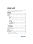
The bracket in this example consists of 926 nodes and 1719 S3R elements. The model contains seven
different element sets. Each element set has a different thickness and is modeled as a laminated composite
with 20 layers.
Ten unrestrained vibration modes are computed. The first six frequencies are approximately zero.
The frequencies for the first four flexible modes are listed in Table 4–1.
4–1
Abaqus ID:
Printed on:
EXAMPLES
Table 4–1
Frequencies for the first four flexible modes for the fiber-filled bracket.
Mode
Frequency,
Hz
7
334
8
430
9
740
10
752
The Abaqus finite element model is shown in Figure 4–1.
Figure 4–1
Finite element mesh of the fiber-filled bracket.
The complete input file, moldflow_ex1.inp, is shown below.
***************************************************************
**
** translated data from the Moldflow interface files named
4–2
Abaqus ID:
Printed on:
EXAMPLES
** "moldflow_ex1.pat"
** and
** "moldflow_ex1.osp"
**
** to the following Abaqus input files:
**
**
input file = moldflow_ex1.inp: YES
**
** neutral material file = moldflow_ex1.shf: YES
**
(for *ELASTIC/*EXPANSION data)
**
**
initial stress file = moldflow_ex1.str: YES
**
(for *INITIAL CONDITIONS data)
**------------------------------------------------------------** echo of header information from the Moldflow interface
** files:
**
** TITL information from .osp file:
** TITL
**
** FILE information from .osp file:
** FILE JUN14-2002 11:13:29 mpi310 Residual Stress &
** Properties
**
**
number of nodal properties = 0
**
number of element properties = 13
**
number of nodes = 926
**
number of TRI elements = 1719
**
number of 1D elements = 0
**
** Moldflow results were written with ISP coding, i.e.,
** this is a filled anisotropic material with residual stresses
**
------ -------------**------------------------------------------------------------** this input file was created with the following keyword data:
**
**
*NODE
(926 nodes)
**
**
*ELEMENT (1719 S3R elements)
**
**
*SHELL SECTION, COMPOSITE (7 ELSETs)
4–3
Abaqus ID:
Printed on:
EXAMPLES
**
**
*MATERIAL
**
*ELASTIC, TYPE=SHORT FIBER
**
*EXPANSION, TYPE=SHORT FIBER
**
(elastic and expansion data will be read from file
**
moldflow_ex1.shf)
**
**
*INITIAL CONDITIONS, TYPE=STRESS, SECTION POINTS,
**
INPUT=moldflow_ex1.str
**
**
*STEP
**
(Dummy step data. Loads and boundary conditions
**
may need to be added to complete the model.)
***************************************************************
*HEADING
TITL
***************************************************************
*NODE, NSET=NALL, INPUT=moldflow_ex1_nodes.inp
***************************************************************
*ELEMENT, TYPE=S3R, ELSET=EALL, INPUT=moldflow_ex1_elements.inp
***************************************************************
*INCLUDE, INPUT=moldflow_ex1_elsets.inp
***************************************************************
*INCLUDE, INPUT=moldflow_ex1_sections.inp
***************************************************************
*MATERIAL,NAME=moldflow_mat_01
*ELASTIC,TYPE=SHORT FIBER
*EXPANSION,TYPE=SHORT FIBER
*DENSITY
1500.,
***************************************************************
*INITIAL CONDITIONS,TYPE=STRESS,SECTION POINTS,
INPUT=moldflow_ex1.str
***************************************************************
*STEP
*FREQUENCY, EIGENSOLVER=LANCZOS
10,
*END STEP
**
** SIGN: ljoXzAUD!NPKmw==
**
4–4
Abaqus ID:
Printed on:
EXAMPLES
4.3
Example 2: Natural frequency analysis of an unfilled bracket
This example uses the same Abaqus finite element model as Example 1, but the material properties are
transversely isotropic. The shell section definition is homogeneous instead of composite. Twenty-one
equally spaced Simpson integration points are used through the shell thickness.
The frequencies for the first four flexible vibration modes of the unfilled bracket are listed in
Table 4–2. The unfilled material in this example is softer than the filled material in Example 1 and,
consequently, the frequencies are lower.
Table 4–2
Frequencies for the first four flexible modes for the unfilled bracket.
Mode
Frequency,
Hz
7
146
8
217
9
363
10
371
The complete input file, moldflow_ex2.inp, is shown below.
***************************************************************
**
** translated data from the Moldflow interface files named
** "moldflow_ex2.pat"
** and
** "moldflow_ex2.osp"
**
** to the following Abaqus input files:
**
**
input file = moldflow_ex2.inp: YES
**
** neutral material file = moldflow_ex2.shf: NO
**
(for *ELASTIC/*EXPANSION data)
**
**
initial stress file = moldflow_ex2.str: YES
**
(for *INITIAL CONDITIONS data)
**-------------------------------------------------------------
4–5
Abaqus ID:
Printed on:
EXAMPLES
** echo of header information from the Moldflow interface
** files:
**
** TITL information from .osp file:
** TITL
**
** FILE information from .osp file:
** FILE JUN14-2002 11:19:59 mpi310 Residual Stress &
** Properties
**
**
number of nodal properties = 0
**
number of element properties = 45
**
number of nodes = 958
**
number of TRI elements = 1719
**
number of 1D elements = 32
**
** Moldflow results were written with IST coding, i.e.,
** this is an unfilled anisotropic material with residual
** stresses
**
-------- -------------**------------------------------------------------------------** this input file was created with the following keyword data:
**
**
*NODE
(926 nodes)
**
**
*ELEMENT (1719 S3R elements)
**
**
*SHELL SECTION, COMPOSITE (7 ELSETs)
**
**
*MATERIAL
**
*ELASTIC, TYPE=SHORT FIBER
**
*EXPANSION, TYPE=SHORT FIBER
**
(elastic and expansion data will be read from file
**
moldflow_ex2.shf)
**
**
*INITIAL CONDITIONS, TYPE=STRESS, SECTION POINTS,
**
INPUT=moldflow_ex2.str
**
**
*STEP
**
(Dummy step data. Loads and boundary conditions
**
may need to be added to complete the model.)
4–6
Abaqus ID:
Printed on:
EXAMPLES
***************************************************************
*HEADING
TITL
***************************************************************
*NODE, NSET=NALL, INPUT=moldflow_ex2_nodes.inp
***************************************************************
*ELEMENT, TYPE=S3R, ELSET=EALL, INPUT=moldflow_ex2_elements.inp
***************************************************************
*INCLUDE, INPUT=moldflow_ex2_elsets.inp
***************************************************************
*INCLUDE, INPUT=moldflow_ex2_sections.inp
***************************************************************
*MATERIAL,NAME=moldflow_mat_01
*ELASTIC,TYPE=SHORT FIBER
*EXPANSION,TYPE=SHORT FIBER
*DENSITY
1500.,
***************************************************************
*INITIAL CONDITIONS,TYPE=STRESS,SECTION POINTS,
INPUT=moldflow_ex2.str
***************************************************************
*STEP
*FREQUENCY, EIGENSOLVER=LANCZOS
10,
*END STEP
4.4
Example 3: Deformation due to initial stresses in a
three-dimensional filled bracket
This example uses a solid Abaqus finite element model that is similar to the model used in Example 1.
To execute the Abaqus Interface for Moldflow, enter the following command:
abaqus moldflow job=bracket3d_mpi6 3D initial_stress=on
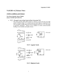
A contour plot of initial stresses is shown in Figure 4–2.
4–7
Abaqus ID:
Printed on:
EXAMPLES
S, Mises
(Avg: 75%)
+8.424e+07
+7.787e+07
+7.150e+07
+6.513e+07
+5.876e+07
+5.239e+07
+4.601e+07
+3.964e+07
+3.327e+07
+2.690e+07
+2.053e+07
+1.416e+07
+7.791e+06
Figure 4–2
Contour plot of the initial stresses for the filled bracket using Moldflow Version MPI 6.
4–8
Abaqus ID:
Printed on:
About Dassault Systèmes
As a world leader in 3D and Product Lifecycle Management (PLM) solutions,
Dassault Systèmes brings value to more than 100,000 customers in 80 countries.
A pioneer in the 3D software market since 1981, Dassault Systèmes develops and
markets PLM application software and services that support industrial processes
and provide a 3D vision of the entire lifecycle of products from conception to
maintenance to recycling. The Dassault Systèmes portfolio consists of CATIA for
designing the virtual product, SolidWorks for 3D mechanical design, DELMIA for
virtual production, SIMULIA for virtual testing, ENOVIA for global collaborative
lifecycle management, and 3DVIA for online 3D lifelike experiences. Dassault
Systèmes’ shares are listed on Euronext Paris (#13065, DSY.PA), and Dassault
Systèmes’ ADRs may be traded on the US Over-The-Counter (OTC) market (DASTY).
For more information, visit www.3ds.com.
Abaqus, the 3DS logo, SIMULIA, CATIA, SolidWorks, DELMIA, ENOVIA, 3DVIA, and Unified FEA are trademarks or registered trademarks of Dassault Systèmes or its
subsidiaries in the US and/or other countries. Other company, product, and service names may be trademarks or service marks of their respective owners. © Dassault Systèmes, 2012
SIMULIA is the Dassault Systèmes brand that delivers a scalable portfolio of
Realistic Simulation solutions including the Abaqus product suite for Unified Finite
Element Analysis; multiphysics solutions for insight into challenging engineering
problems; and lifecycle management solutions for managing simulation data,
processes, and intellectual property. By building on established technology,
respected quality, and superior customer service, SIMULIA makes realistic
simulation an integral business practice that improves product performance,
reduces physical prototypes, and drives innovation. Headquartered in Providence,
RI, USA, with R&D centers in Providence and in Vélizy, France, SIMULIA provides
sales, services, and support through a global network of regional offices and
distributors. For more information, visit www.simulia.com.
www.3ds.com
About SIMULIA