1
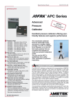
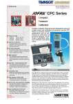
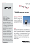
Reference Manual Compact Pressure Calibrator AMETEK JOFRA CPC Copyright 2005 AMETEK Denmark A/S 1. Introduction The AMETEK JOFRA CPC is designed to verify and calibrate pressure gauges, transducers, pressure switches, safety valves, P/I transmitters, perform pressure switch tests, and measure current and pressure. Current and pressure measurements are simultaneously displayed on the calibrator. The calibrator can measure vacuum and pressure up to 10 psi / 0.7 bar, 30 psi / 2 bar, or 200 psi / 15 bar depending on sensor type and current up to 24mA. 1.1 Contacting Ametek US, Canada, Latin America Europe, Africa, Middle East Asia AMETEK TCI at 1-800-527-9999 AMETEK Denmark A/S at + 45 4816 8000 AMETEK Singapore Pte. Ltd. at + 65 (64) 842 388 1.2 Standard Equipment Inspect the unit carefully upon receipt. Save packing carton in case reshipment is necessary. If there appears to be any damage, equipment missing or if there are any questions about the unit, contact AMETEK. Check to see if your calibrator is complete. It should include: • CPC Calibrator • Instruction Manual • Test Leads • Carrying Case 1.3 Safety information Symbols Used The following table lists the International Electrical Symbols. Some or all of these symbols may be used on the instrument or in this manual. Symbol Description AC (Alternating Current) AC-DC Battery CE Complies with European Union Directives 1 DC Double Insulated Electric Shock Fuse PE Ground Hot Surface (Burn Hazard) Read the User’s Manual (Important Information) Off On Canadian Standards Association This calibrator must be recycled or disposed of properly (2002/95/EC). The following definitions apply to the terms “Warning” and “Caution”. • “Warning” identifies conditions and actions that may pose hazards to the user. • “Caution” identifies conditions and actions that may damage the instrument being used. Use the calibrator only as specified in this manual, otherwise injury and damage to the calibrator may occur. Warning To avoid possible electric shock or personal injury: • Do not apply more than the rated voltage. See specifications for supported ranges. • Pressure switches must not be connected to any other voltage source during a test. 2 • Follow all equipment safety procedures. • Never touch the probe to a voltage source when the test leads are plugged into the current terminals. • Do not use the calibrator if it is damaged. Before you use the calibrator, inspect the case. Look for cracks or missing plastic. Pay particular attention to the insulation surrounding the connectors. • Select the proper function and range for your measurement. • Make sure the battery cover is closed and latched before you operate the calibrator. • Remove test leads from the calibrator before you open the battery door. • Inspect the test leads for damaged insulation or exposed metal. Check test leads continuity. Replace damaged test leads before you use the calibrator. • When using the probes, keep your fingers away from the probe contacts. Keep your fingers behind the finger guards on the probes. • Connect the common test lead before you connect the live test lead. When you disconnect test leads, disconnect the live test lead first. • Do not use the calibrator if it operates abnormally. Protection may be impaired. When in doubt, have the calibrator serviced. • Do not operate the calibrator around explosive gas, vapor, or dust. • When using a pressure module, make sure the process pressure line is shut off and depressurized before you connect it or disconnect it from the CPC or pressure module. • Disconnect test leads before changing to another measure or source function. • When servicing the calibrator, use only specified replacement parts. • To avoid false readings, which could lead to possible electric shock or personal injury, replace the battery as soon as the battery indicator appears. • To avoid personal injury or damage to the calibrator, use only the specified replacement parts and do not allow water into the case Caution To avoid possible damage to calibrator or to equipment under test: • Disconnect the power and discharge all high-voltage capacitors before testing resistance or continuity. • Use the proper jacks, function, and range for your measurement or sourcing application. 3 • If the message changes to "OL" the range limit is exceeded and the pressure source must immediately be removed from the CPC to prevent damage to the pressure transducer inside. • Maximum torque allowed is 13.5 Nm /10 ftlbs. NEVER exceed the torque allowed. • To avoid damaging the plastic lens and case, do not use solvents or abrasive cleansers. Clean the calibrator with a soft cloth dampened with water or water and mild soap. 2. Calibrator Display and Controls 2.1 Display and Inputs The calibrator display has two numeric displays. The large display shows the measured pressure, and the small display shows the measured current. The measured current may be displayed in mA or in percentage of mA range (4mA - 20mA), where 0% corresponds to 4mA and 100% to 20mA. Pressure units are located on the right side of the display. For a listing of all the units supported refer to the table in the Specifications section. The calibrator has two sets of input terminals located on top of the unit, and a pressure fitting located on the bottom of the unit. The input terminals on the right are used for measuring current. The terminals on the left are used for pressure switch connection. 2.2 Key Functions Figure 1 shows the layout of the calibrator keypad while Table 1 lists the calibrator keys and their functions. 4 Table 1: Key Functions Key Function 1 Turns the unit on and off 2 Select different pressure units. Press and hold while unit is powering up to change the power saver setting. 3 Switches the mA numeric display between mA and percentage of range. 4 Zeroes the pressure sensor. 5 Turns on the switch test mode. Hold to clear previous test. 6 Displays the minimum and maximum pressure and current measured since power up. Figure 1 5 2.3 Power Saver The calibrator has an adjustable power saver option that allows it to shut down after being dormant for a period of 1 to 30 minutes. To set the shutoff time: 1. Press and hold the (UNITS) key while powering up the unit. 2. A number from 1 to 30 or OFF will appear on the bottom of the display. 3. Use the units key to scroll the numbers up, and the(MAX/MIN) key to scroll down. 4. Press the (ZERO) key to set the time. 3. Measuring Pressure and Current Warning Make sure the process pressure line is shut off and depressurized before you connect it or disconnect it from the APC or pressure module. Caution • If the message changes to "OL" the range limit is exceeded and the pressure source must immediately be removed from the APC to prevent damage to the pressure transducer inside. • Maximum torque allowed is 13.5 Nm /10 ftlbs. NEVER exceed the torque allowed. To measure pressure, connect the calibrator using an appropriate fitting. Choose a pressure unit for measurement with the (UNITS) key. Pressure will be displayed on the large numeric display. Use the (ZERO) key to zero the pressure sensor when vented to atmospheric pressure Important NOTE: It is critical to ensure accuracy of the calibrator to zero the CPC before a device is calibrated. To measure current use the mA input terminals on the top of the calibrator. Current can be measured in mA or percentage of range. The range on the calibrator is set to 0% at 4mA and 100% at 20mA. For for example if the current measured is displayed as 75% then the mA value is 16mA. 6 3.1 Media Compatibility The CPC calibrator utilizes a media isolated sensor to prevent sensor contamination. Whenever possible clean, dry air is the media of choice, but if that is not always possible, make sure that the media is compatible with the following wetted parts: 1) Nickel plated brass 2) Glass 3) RTV (silicone) 4) BUNA-N 3.2 Minimum and Maximum Measurements The calibrator automatically records the maximum and minimum values for pressure that were read by the calibrator since it has been turned on or reset. The current or mA reading is also stored for the corresponding pressure value. To call up the recorded values from memory press the (MAX/MIN) key. To clear the memory press and hold the MAX/MIN key until “CLR” is displayed. 4. Calibrating a P/I Transmitter Warning • Do not apply more than the rated voltage. See specifications for supported ranges. • Pressure switches must not be connected to any other voltage source during a test Caution • Disconnect the power and discharge all high-voltage capacitors before testing resistance or continuity. To calibrator a pressure-to-current transmitter, perform the following steps: 1. Connect the calibrator and the pump to the transmitter as shown in the setup in Figure 2. 2. Apply pressure with the pump. 3. Measure the current output of the transmitter. 4. Ensure the output is correct. If not, adjust the transmitter as necessary. 7 Figure 2 5. Performing a Pressure Switch Test Warning • Do not apply more than the rated voltage. See specifications for supported ranges. To perform a switch test, follow these steps: 1. Connect the calibrator to the switch using the pressure switch terminals, and connect the pump to the calibrator and the pressure switch. The polarity of the terminals does not matter. This set up is shown in Figure 3. 2. Make sure the vent on the pump is open, and zero the calibrator if necessary. Close the vent after zeroing the calibrator. 3. Press the (SWITCH TEST) key to enter pressure switch test mode. The calibrator will display CLOSE instead of a mA measurement. 4. Apply pressure with the pump slowly until the switch opens. Important Note: In the switch test mode the display update rate is increased to help capture changing pressure inputs. Even with this 8 enhanced sample rate pressurizing the device under test should be done slowly to ensure accurate readings. 5. Once the switch is open, OPEN will be displayed, bleed the pump slowly until the pressure switch closes. RECALL will appear on the display. 6. Press the (SWITCH TEST) key to read the pressure values for when the switch opened, for when it closed, and for the dead band. 7. Hold the (SWITCH TEST) key to clear the data and perform another test. 8. Press the (mA/%) key to cancel the test. Important NOTE: The above example uses a normally closed switch. The basic procedure is still the same for a normally open switch, the display will just read OPEN instead of CLOSE. Figure 3 9 6. Specifications Table 1: Pressure Pressure range in bar Vacuum to 0.7, 2, or 15bar Pressure range in psi Vacuum to 10, 30, or 200psi Supported pressure units psi, bar, mbar, kg/cm2, inH2O @ 4°C, inH2O @20°C, inH2O @60°C, mH2O @4°C, mH2O @20°C, cmH2O @4°C, cmH2O @20°C, ftH2O @4°C, ftH2O @20°C, ftH2O @60°C, inHg @0°C, mmHg @0°C, kPa Overload maximum +50%F.S. Overload alarm Activates at +20%F.S. Connection 1/8in NPT female Positive accuracy ± 0.05% of F.S. Vacuum accuracy ± 0.1% of F.S. Operating temperature -10°C to 50°C / 14°F to 122°F Storage temperature -20°C to 60°C / -4°F to 140°F Temperature Compensation for pressure and electrical ± 0.005% F.S./ °C outside 18 to 28°C ± 0.003% F.S./ °F outside 64 to 82°F Table 2: General Specifications LCD Dual information LCD plus icon indicators Display resolution 5 digits Display update Approximately 4 times per second Switch test capture 50 milliseconds mA input 0-24mA Accuracy: ± 0.015% of reading ± 2µA Switch test Supply max 9V Batteries 1x9V Alkaline Low battery indicator 7V Size 188mm x 84mm x 52mm / 7.37in x 3.31in x 2.05in Weight 400g / 14.1oz All above specifications are specified at 23°C ± 5°C / 74.3°F ± 9°F unless otherwise noted. 10 7. Maintenance 7.1 Replacing Batteries Replace batteries as soon as the battery indicator turns on to avoid false measurements. Note: Use only 9 Volt alkaline battery. 7.2 Cleaning the Unit Warning To avoid personal injury or damage to the calibrator, use only the specified replacement parts and do not allow water into the case. Caution To avoid damaging the plastic lens and case, do not use solvents or abrasive cleansers. Clean the calibrator with a soft cloth dampened with water or water and mild soap. 11 7.3 Service Center Calibration or Repair Only qualified service personnel should perform calibration, repairs, or servicing not covered in this manual. If the calibrator fails, check the batteries first, and replace them if needed. Verify that the calibrator is being operated as explained in this manual. If the calibrator is faulty, send a description of the failure with the calibrator. Be sure to pack the calibrator securely, using the original shipping container if it is available. 7.4 Replacement Parts & Accessories Order Number Description SPK-CPC-001 Operating Manual SPK-HHC-002 124109 124110 Soft carrying case System A carrying case System B carrying case 104203 Test Lead Set 65R191 BSP Fittings and Tape - 1/4 BSP Male x 1/8, 3/8, and 1/2 BSP Female NPT Fittings and Tape - 1/4 BSP Male x 1/8, 3/8, and 1/2 NPT Female Set of Seals for 65R191 or 65R192 Fitting Kits System Quick Connect Fitting - for use with T-910 - 3/8" BSP Male termination System Quick Connect Fitting - for use with T-730/740 - 1/4" NPT Male termination Fitting - 1/8 NPT Male x 1/4 BSP Female Fitting - 1/8 NPT Male x 1/4 NPT Female Teflon Tape RS232 - Stereo to Serial connection Shoulder strap with snap hooks Adapter - 1/4" NPT Male x 1/4" BSP Female - For use with AMETEK handpump hoses 65R192 60R191 SPK-HPC-001 SPK-HPC-002 60R178 60R166 60I104 123958 124004 T-786 T-730 T-740 T-750 T-910 T-746 T-747 75P012 12 Pneumatic Handpump - 0 to 30 psi / 0 to 2 bar Pneumatic Handpump - 0 to 300 psi / 0 to 21 bar Pneumatic Handpump - Vacuum to 0 psi / Vacuum to 0 bar Pneumatic Handpump - Vacuum to 600 psi / Vacuum to 40 bar Service Kit for T-730 and T-740 Handpumps Service Kit for T-750 Handpump Service Kit for T-910 Handpump SPK-CPC-001 Rev C 6/05 0219104 ...because calibration is a matter of confidence AMETEK Calibration Instruments offers a complete range of calibration equipment for pressure, temperature, and signal - including software. JOFRA Temperature standards Portable precision thermometer. Dry-block calibrators: 4 series, more than 20 models - featuring speed, portability, accuracy, and advanced documenting functions. M&G Primary pressure standards Pneumatic floating-ball or hydraulic piston deadweight testers - easy-to-use with accuracies up to 0.015% of reading. JOFRA Pressure standards Convenient electronic systems ranging from -1 to 700 bar (25 inHg to 10,000 psi) - multiple choices of pressure ranges, pumps, and accuracies, fully temperature-compensated for problem-free and accurate field use. JOFRA Signal calibration Process signal measurement and simulation for easy control loop calibration and measurement tasks from handheld field instruments for multi or single signals to laboratory reference level bench top instruments. AMETEK is a leading global manufacturer of electrical and electromechanical products for niche markets. Listed on the New York Stock Exchange (AME) since 1930. AMETEK’s annual sales exceed $1 billion. Operations are in North America, Europe, and Asia, with about one third of sales to markets outside the United States. CALIBRATION INSTRUMENTS www.ametekcalibration.com www.jofra.com AMETEK Test & Calibration Instruments • Florida, USA (Western Hemisphere) Tel: +1 727-536-7831 • Tel: +1 800-527-9999 • calinfo.us@ametek.com AMETEK Denmark A/S • Denmark (Europe and the Middle East) Tel: +45 4816 8000 • ametek@ametek.dk AMETEK Precision Instruments Europe GmbH • Germany (Germany only) Tel: +49 2159 91360 • info@ametek.de AMETEK Singapore Pte. Ltd. • Singapore (Asia) Tel: +65 6 484 2388 • aspl@ametek.com.sg Information within this document is subject to change without notice. All rights reserved.