1
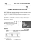
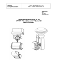
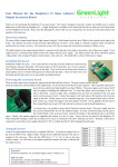
Siemens
Energy & Automation
INSTALLATION AND SERVICE INSTRUCTION
SD73
Rev 12
December 2005
Supersedes Rev 11
MODEL 73N BUILT-IN VALVE POSITIONER
The Model 73N is a Built-in Valve Positioner which is mounted directly on the topworks of a valve. It is capable of
utilizing the full force of its air supply to drive the piston or diaphragm, in a pneumatic actuator, to a position called
for by the control instrument. The positioner incorporates a single-axis force-balance principle of operation to insure
accurate and stable positioning of a control valve.
MODEL DESIGNATION
73N
12
F
Basic Model Number
Input Span – psig
Special Feaures
F — Fast response
R — Reverse acting
E — Tapped Exhaust
USM — U.S. Electrical Motors Type
Fast Response: The fast response positioner is used on actuators with large volume topworks requiring a fast
response action. Due to increased pilot plunger travel and larger ports in the fast response positioner, greater filling
and exhausting capacities result. This permits a quicker response to a change in control conditions, plus increased
speed of valve operation.
Tapped Exhaust: The Model 73N Positioner can be ordered with a tapped exhaust port. This feature permits piping
of the pilot exhaust to a safe atmosphere on applications where noxious gases are used as a control medium instead
of air.
USM: On actuators with small topworks and a low volume, a special hi-response positioner may be used. This
positioner is denoted by the letters USM in the model number. There is no bleed on this model due to the low
volume. A special valve plunger is used to ensure fast response for close control.
GENERAL SPECIFICATIONS
Instrument Input Pressure Range...................3-15, 3-9, 9-15, and 3-27 psig
Supply Pressure
Minimum................................................3 psi above required actuator pressure
Maximum ...............................................100 psi
Air Consumption ...........................................0.25 SCFM (in balance condition with 20 psi supply and 9 psi dead
ended output)
Valve Travel
Minimum................................................1/4"
Maximum ...............................................4"
Ambient Temperature Limits ........................-40°C to +82°C (-40°F to +180°F)
SD73
INSTALLATION
Refer to Figure 1 for mounting dimensions and connections. A centering washer (customer provided) which fits the
I.D. of the range spring should be used. This acts as a spring seat and keeps the spring from shifting.
Mounting hardware is included with the positioner in a plastic bag numbered 10448-88. It contains (6) mounting
screws and washers, (1) range spring seat and (1) gasket.
CAUTION
Exceeding the specified ambient temperature limits can adversely affect performance
and may cause the positioner to fail.
1.
Place centering washer on the actuator's diaphragm or piston.
2.
Place the positioner range spring on the center of the actuator diaphragm or piston.
3.
Place the gasket on the mounting flange of the actuator top works. Substitute the P/N 10636-59 centering
diaphragm for the gasket if the P/N 12388-6412 or 12395-6412 range spring is used.
4.
Place the positioner range spring seat on the center nut of the positioner diaphragm assembly.
5.
Hold the spring seat and guide the positioner and seat onto the range spring.
6.
Orient the positioner for desired location of connections.
7.
Insert mounting screws and washers and tighten screws.
PNEUMATIC CONNECTIONS
1.
All connections are 1/4" NPT.
2.
The piping recommended for the positioner is 1/4" O.D. tubing for the INSTRUMENT (input) connection and
3/8" O.D. tubing for the supply connection. However, any scale-free piping may be used.
3.
Blow out all piping before connections are made to prevent dirt, chips, etc., from entering the positioner.
4.
Use pipe sealant sparingly and then only on the male threads. A non-hardening sealant is strongly
recommended.
5.
Connect the positioner to a source of clean, dry, oil-free instrument air supply (see INSTRUMENT AIR
REQUIREMENTS).
CAUTION
Pressure in excess of 150 psig to any connection may cause damage.
INSTRUMENT AIR REQUIREMENTS
Connect the positioner to a source of clean, dry, oil-free supply air. Failure to do so will increase the possibility of a
malfunction or deviation from specified performance.
CAUTION
Use of process fluids other than instrument air is not recommended. No claim is made as to
the suitability of this product for use with other process fluids, such as hazardous gases,
except as listed on the appropriate certificate. Non-approved instruments are suitable for
use with instrument air only. Optional features and modifications such as tapped exhaust do
not imply suitability for use with hazardous gases except as listed on the approval
certificate.
CAUTION
Synthetic compressor lubricants in the air stream at the instrument may cause the positioner
to fail.
2
SD73
There are many types of synthetic lubricants. Some may not be compatible with the materials used in the
construction of the positioner. Wetting of these materials by such an oil mist or oil vapor, etc., may cause them to
deteriorate. This may ultimately result in failure of the positioner. The following materials are in contact with supply
air: Aluminum, Brass, Stainless Steel, Neoprene and Buna-N.
The requirements for a quality air supply can be found in the Instrument Society of America's "Quality Standard for
Instrument Air" (ISA-S7.3). Basically this standard calls for the following:
Particle Size — Maximum particle size in the air stream should be no larger than 3 microns.
Figure 1 Installation Dimensions and Connections
3
SD73
Dew Point — Dew point at line pressure should be at least 10°C (18°F) below the minimum temperature to which
any part of the instrument air system is exposed at any season of the year. Under no circumstances should the dew
point at line pressure exceed 2°C (35.6°F).
Oil Content — Maximum total oil or hydrocarbon content, exclusive of non-condensables, should not exceed 1 ppm
under normal operating conditions.
CAUTION
Exceeding the specified ambient temperature limits can adversely affect performance and
may cause damage.
ADJUSTMENT
The only adjustment that can be made on the positioner is a zero adjustment. The zero adjusting screw is located
under the positioner top cover.
To adjust the zero, set the instrument pressure to the midpoint of its span, and turn the zero adjustment until the
valve is at the mid-point of its stroke.
In some cases, valve shut-off or opening may be required at a specific instrument pressure. To zero the positioner at
this point, set the instrument pressure at the specific pressure and turn the zero adjustment screw until the valve
reaches the required position.
A slight change of the instrument pressure should start to move the valve.
The valve stroke for a given span may also be suppressed or shifted to the desired range by means of the zero
adjusting screw.
RANGE SPRING SELECTION
Range springs for the positioner are selected from the table in Figure 2. Color coding of the range springs is given
by the table in Figure 3.
To find the proper spring, select the stroke listed which most nearly agrees with the desired stroke, and the pressure
span which most nearly agrees with the desired span. The proper spring will be found at the intersection of these two
columns.
Series 4090 and 12395 range springs are available for stroke range tolerances of ±10%. Series 12388 range springs
are available, at extra cost, for stroke range tolerances of ±5%.
4
SD73
4
Valve Stroke
(inches)
1/4
5/16
3/8
7/16
1/2
9/16
5/8
3/4
7/8
1
1-1/8
1-1/4
1-1/2
1-5/8
1-3/4
2
2-1/4
2-1/2
2-3/4
3
3-1/2
4
5
Input Pressure Span (see Special Notes below)
6
8
10
12
16
20
24
Item No. of Range Spring Series 12395 Series +/- 5% stroke range tolerance
1212
1812
1812
2012
2412
2812
3212
3612
4412
4812
5612
6412
1012
1212
1412
1812
2012
2012
2412
2812
3612
4012
4412
4812
6412
6412
6412
812
1012
1212
1412
1612
1812
2012
2412
2812
3212
3612
4012
4812
4812
5612
6412
6412
612
712
1012
1012
1212
1412
1612
1812
2012
2412
2812
3212
3612
4012
4412
4812
5612
6412
6412
512
612
712
812
1012
1012
1212
1412
1812
2012
2012
2412
2812
3212
3612
4012
4412
4812
4812
6412
412
512
612
712
812
1012
1012
1212
1412
1612
1812
2012
2412
2612
2812
3212
3612
4012
4412
4812
5612
6412
624
824
1024
1024
1224
1424
1624
2024
2424
2824
4024
4024
4024
4824
524
624
724
824
1024
1024
1224
1464
1624
2024
2024
2424
2824
3224
3224
4024
4024
4824
4824
424
524
624
724
824
1024
1224
1424
1624
2024
2424
2824
3224
4024
4824
4824
Special Notes:
1) All range springs are identified as Part No. (P/N) 12395-______(# from table)
2) Input pressure span = pressure @ max. input – (minus) pressure @ min input, e.g. @ 3-15 psig range = @ 12
psig span
Spring Selection:
1) Find valve stroke nearest desired valve stroke.
2) Find instrument input pressure span nearest desired instrument input pressure span.
3) Select proper range spring at intersection of valve stroke and instrument input pressure span columns.
Springs purchased with models are quoted as model discounts all others get spare parts pricing.
Notes:
1) The maximum zero pressure for the Model 73N12F is 9 psig when the 12395 series range spring is used.
2) The maximum zero pressure for the Model 73N24F is 15 psig for instrument pressure spans of 16 psi or greater
and 28 psig when used for spans of 12 psi or less.
3) The maximum instrument pressure for the Model 73N-FR is 15 psig for instrument pressure spans of 12 psi or
less and 27 psi for spans of 16 psi or greater.
Figure 2 Range Spring Index
5
SD73
MAINTENANCE GENERAL
Clean, dry, oil-free instrument air will reduce most
problems associated with pneumatic instruments.
Refer to INSTRUMENT AIR REQUIREMENTS.
If these requirements are observed, no routine
maintenance is recommended. Cleaning the
plunger is to only maintenance which may be
required on an occasional basis.
The system should be shut down or the valve
isolated from the system before service or removal
of the positioner is accomplished.
CLEANING (Refer to parts list)
The plunger can be cleaned without dismantling
the positioner. Use the following procedure:
1.
Turn off the supply air.
2.
Remove the positioner top cover.
3.
Remove the retaining nut.
4.
Remove the plunger.
5.
Use a non-abrasive solvent to clean the
plunger.
6.
Replace the plunger.
7.
Replace and tighten the retaining nut.
8.
Replace the top cover.
DISASSEMBLY (Refer to parts list)
1.
Loosen the six socket head mounting screws
holding the positioner to the actuator.
2.
Remove the positioner.
3.
Remove the two body screws holding the
diaphragm stack assembly to the positioner
body (located on the underside of the stack).
4.
The diaphragm stack assembly can be further
disassembled by removing the diaphragm jam
nut.
ASSEMBLY (Refer to parts list)
To assemble, reverse the disassembly procedures.
Take care to insure proper alignment of the
diaphragms and rings. When tightening the jam nut
on the diaphragm assembly, make sure the
diaphragms do not rotate out of position.
Figure 3 Range and Zero Spring Color Codes
An alignment slot is provided on the rings to
facilitate proper assembly.
6
SD73
Figure 4 Schematic – Direct Acting
Figure 5 Schematic – Reverse Acting
7
SD73
PRODUCT SUPPORT
This section provides the Internet site addresses, e-mail addresses, telephone numbers, and related information for
customers to access Siemens product support.
When contacting Siemens for support:
•
•
Please have complete product information at hand:
•
For hardware, this information is provided on the product nameplate (part number or model number,
serial number, and/or version).
•
For most software, this information is given in the Help > About screen.
If there is a problem with product operation:
•
Is the problem intermittent or repeatable? What symptoms have been observed?
•
What steps, configuration changes, loop modifications, etc. were performed before the problem
occurred?
•
What status messages, error messages, or LED indications are displayed?
•
What troubleshooting steps have been performed?
•
Is the installation environment (e.g. temperature, humidity) within the product’s specified operating
parameters? For software, does the PC meet or exceed the minimum requirements (e.g. processor,
memory, operating system)?
•
A copy of the product Service Instruction, User’s Manual, or other technical literature should be at hand. The
Siemens public Internet site (see the table) has current revisions of technical literature, in Portable Document
Format, for downloading.
•
To send an instrument to Siemens for repair, request a Return Material Authorization (RMA).
IMPORTANT
An instrument must be thoroughly cleaned (decontaminated) to remove any process materials,
hazardous materials, or blood born pathogens prior to return for repair. Read and complete the
Siemens RMA form(s).
Contact Information
United States
of America
Telephone
Fax
E-mail
Hours of Operation
Public Internet Site
Repair Service
+1 800 569 2132, option 2 for Siemens and Moore brand instruments
+1 215 646 3547
PITechSupp@sea.siemens.com
8 a.m. to 4:45 p.m. eastern time
Monday – Friday (except holidays)
www.sea.siemens.com/ia/
+1 215 646 7400 extension 3187
For contact information outside the U.S.A., visit the Siemens public Internet site (see the above table for the URL),
locate “Customer Support Process Instrumentation,” and click on the Contact Tech Support link to access the Global
Support link.
Current revisions of instructions and manuals, in Portable Document Format (PDF), can be found at the Siemens
public Internet site.
8
SD73
WARRANTY
(a) Seller warrants that on the date of shipment the goods are of the kind and quality described herein and
are free of non-conformities in workmanship and material. This warranty does not apply to goods
delivered by Seller but manufactured by others.
(b) Buyer's exclusive remedy for a nonconformity in any item of the goods shall be the repair or the
replacement (at Seller's option) of the item and any affected part of the goods. Seller’s obligation to repair
or replace shall be in effect for a period of one (1) year from initial operation of the goods but not more
than eighteen (18) months from Seller’s shipment of the goods, provided Buyer has sent written notice
within that period of time to Seller that the goods do not conform to the above warranty. Repaired and
replacement parts shall be warranted for the remainder of the original period of notification set forth above,
but in no event less than 12 months from repair or replacement. At its expense, Buyer shall remove and
ship to Seller any such nonconforming items and shall reinstall the repaired or replaced parts. Buyer shall
grant Seller access to the goods at all reasonable times in order for Seller to determine any nonconformity
in the goods. Seller shall have the right of disposal of items replaced by it. If Seller is unable or unwilling
to repair or replace, or if repair or replacement does not remedy the nonconformity, Seller and Buyer shall
negotiate an equitable adjustment in the contract price, which may include a full refund of the contract
price for the nonconforming goods.
(c) SELLER HEREBY DISCLAIMS ALL OTHER WARRANTIES, EXPRESS OR IMPLIED, EXCEPT THAT
OF TITLE. SPECIFICALLY, IT DISCLAIMS THE IMPLIED WARRANTIES OF MERCHANTABILITY,
FITNESS FOR A PARTICULAR PURPOSE, COURSE OF DEALING AND USAGE OF TRADE.
(d) Buyer and successors of Buyer are limited to the remedies specified in this article and shall have no
others for a nonconformity in the goods. Buyer agrees that these remedies provide Buyer and its successors
with a minimum adequate remedy and are their exclusive remedies, whether Buyer's or its successors’
remedies are based on contract, warranty, tort (including negligence), strict liability, indemnity, or any
other legal theory, and whether arising out of warranties, representations, instructions, installations, or nonconformities from any cause.
(e) Note: The above does not apply to any software which may be furnished by Seller. In such cases, the
attached Software License Addendum applies.
9
SD73
PARTS LIST
SIEMENS MODEL SERIES 73N BUILT-IN VALVE POSITIONER
Drawing No. 10636PL
3/91 Supersedes 8/88
IMPORTANT
Service Parts Kits are available for servicing the instrument. Contact Siemens for available kits; refer to the Product
Support section of this instruction. Some parts in this Parts List may not be available for separate purchase.
10
SD73
PARTS LIST
SIEMENS MODEL SERIES 73N12FUSM BUILT-IN VALVE POSITIONER
Drawing No. 10976PL
3/91 Supersedes 5/86
IMPORTANT
Service Parts Kits are available for servicing the instrument. Contact Siemens for available kits; refer to the Product
Support section of this instruction. Some parts in this Parts List may not be available for separate purchase.
11