1
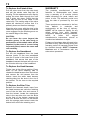
T5
Operating and Maintenance Instructions
WARNINGS
T system users must be familiar with workplace hazards prior to using the equipment and must be fully
trained in the use of the apparatus.
T head-tops must be used with a T/POWER blower. Read this Manual and the T/POWER and T/FILTER User
Manuals, prior to using the equipment.
T/POWER must be fitted with filters selected from the PF or TF range of filters which are appropriate for the
workplace hazard.
This product must only be used with Protector-branded filters manufactured by Scott Health and Safety
Limited. The use of any other filters will negate the approval and will be likely to reduce the level of
protection provided.
DO NOT confuse the AS/NZS1716 : 2003 filter markings with filter markings relating to any other standard.
DO NOT use T5 in confined spaces, oxygen deficient atmospheres (<19.5%), oxygen enriched atmospheres
(>23%) or where there is an immediate hazard to life or health.
Ensure that your selection of respiratory protective devices conform to the requirements AS/NZS1715 :
2009.
T5 helmets are safe to use at -30°C. The respiratory equipment MUST NOT be used below -10°C.
DO NOT use if the apparatus is damaged. The head-top and air hose must be inspected on every occasion
before use to ensure that no damage of any kind is evident, (e.g. chemical damage, splits or broken
stitching), which could cause leakage or reduced levels of protection. A monthly inspection of the
apparatus is strongly recommended.
Exposure to substances such as petrol, paint, adhesives, aerosol sprays or cleaning agents may cause
serious damage to the helmet.
The helmet MUST be replaced if damage is sustained due to severe impact or deterioration.
DO NOT modify or remove individual component parts of the helmet. If it is necessary to replace the head
harness, the replacement head harness MUST be fitted as a complete assembly.
Protection will only be obtained if the unit is fitted correctly.
Protection levels may be reduced if wind speed exceeds 2 metres per second.
In the unlikely event that the T/POWER air supply fails while in a hazardous area, there may be a depletion
of oxygen within the head-top. DO NOT remove the head-top, LEAVE THE AREA IMMEDIATELY.
T head-tops can be used in certain explosive and flammable atmospheres when used with T/POWER which
is marked as intrinsically safe. It is the employer’s responsibility to ensure that the intrinsic safety approval
is compatible with the particular environment.
At very high workrates, pressure in the device may become negative at peak inhalation flow.
Filters must not be fitted directly to the helmet/hood.
1
T5
SPECIFICATION
Description:
Helmet-mounted visor with optional ear
defenders
Classification when used with:
T/POWER
Minimum Design Flow Rate:
AS/NZS1716 : 2003 PAPR-P1
140 L/min
Required Minimum Protection Factor (RMPF) *
when used with:
Particulate Filters
Gas/Vapour Filters
Upto 10 x RMPF
Upto 10 x RMPF
Maximum Gas/Vapour Concentration present in the air:
1000 ppm (by volume)
Operating Temperature Limits:
-10°C to +50°C
Material:
Visor
Weight:
Polycarbonate or Acetate options
890 Grams
* According to AS/NZS1715 : 2009
CAUTION:
•
It is difficult to predict the life of
visors or helmets in use. In
everyday use, and particularly
when used outdoors, we would
recommend
that
visors
or
helmets are discarded after two
years service. In some extreme
instances
there
may
be
deterioration over a shorter
period of time. For indoor or
occasional
use
we
would
anticipate a service life of about
five years, provided that the
equipment is stored in cool dry
conditions out of direct sunlight.
•
Whilst all the materials which
may come into contact with the
wearer's skin are not known to
be likely to cause skin irritation
or any other adverse effect to
health, they may cause allergic
reactions
in
particularly
susceptible individuals.
•
Regardless
of
the
above
recommendations, the visor or
helmets should be examined for
damage such as deep scratches,
abrasions, cracks, etc. before
use and should also be examined
for deterioration. Damaged parts
which have come into contact
with solvents and parts which
have received significant impact
should be replaced.
MARKINGS AND MEANINGS
The T5 head-top
conformance with
follows:
markings are in
AS/NZS1716, as
Head-top Markings:
Marking
Meaning
SCOTT
Manufacturer - Scott Health &
Safety
T5/AC
Product name T5 with Acetate Visor
T5/PC
Product name T5 with Polycarbonate Visor
0086
Certifying body - (BSI)
AS/NZS1716
Australian/New Zealand Standard
PAPR-P1
Class designation
Helmet Markings:
Marking
SHS
Protector
Tuffmaster II
T5
PAPR-P1
AS/NZS1337
AS/NZS1801
Type 1
50 - 64cm
Meaning
Manufacturer’s identification mark
Helmet type
Apparatus type
Class designation - AS/NZS1716
Standard for level of eye protection
Helmet certification - industrial
User head size: lower and upper
limits
WEARING
Note:
Remove the protective transit film from
the outside and inside surfaces of the
visor before donning.
2
T5
1.
Check that the head-top is in good
condition and free from damage that
might reduce respiratory protection and
that the visor is free from blemishes that
might impair vision.
AFTER USE
1.
DO NOT remove the head-top until
safely clear of the hazardous area.
Observe any site decontamination
procedures.
2.
Check that the helmet and helmet
cradle are in good condition and free from
cracks or crazing. Flex the helmet and
check that crazing does not appear.
2.
Disconnect the air hose and use a
synthetic sponge moistened in a warm
soap and water solution to clean the
head-top and air hose. DO NOT permit
water to enter the air hose.
3.
Loosen the head harness using the
handwheel at the back of the harness and
put on the facepiece, slipping the
faceseal under the chin.
3.
Rinse the sponge in clean water
and remove all traces of soap from the
apparatus.
4.
Tighten the handwheel so that the
head harness fits comfortably over the
forehead. It may be necessary to adjust
the helmet cradle so that visor is at the
correct height. If the cradle is adjusted the
head-top fit must be re-adjusted.
4.
Allow the head-top to dry in air at
room temperature. DO NOT store until
thoroughly dry. DO NOT use heat or
sunlight to dry the apparatus. DO NOT
scratch the visor.
5.
Replace
apparatus.
5.
Pull the facepiece back so that it fits
comfortably and securely under the chin
and around the cheeks and the faceseal
around the head, above the ears and
below the head harness.
damaged
items
or
STORAGE
When not in use, the equipment should
be stored in a clean, dry environment,
away from direct heat sources between
+10ºC and +30ºC, at a humidity of less
than 65% RH.
6.
Arrange the air hose so that it trails
freely down the back and is not kinked or
looped; and not likely to snag. Please
refer to the T/POWER User Manual for
further information.
MAINTENANCE
Carry out a thorough inspection of all
component parts before and after each
occasion of use, paying particular
attention to the exhale valve flap. The
valve flap must be replaced annually
regardless of condition. Valve flaps in
storage have a shelf-life of five years,
after which time they should be
discarded.
Exhalation valve flaps are marked with a
code indicating the year of manufacture.
The code ‘07' corresponds to 2007 and a
dot is added each year thereafter, so ‘07.'
would equate to 2008.
3
T5
RECORD INSPECTION AND
MAINTENANCE DETAILS
NOTIFIED BODIES
Inspec International Limited (0194)
56 Leslie Hough Way,
Salford,
Greater Manchester,
M6 6AJ,
England.
Record test and maintenance details on
the Inspection and Maintenance Record
Sheet provided at the back of this
Manual.
Information recorded usually includes:
•
Name of employer responsible for
the apparatus.
•
Make,
model
number
or
identification mark of the apparatus,
together with a description of any
distinguishing features, sufficient to
enable clear identification.
•
Date
of
the
inspection/
maintenance together with the
name,
signature
or
unique
authentication
mark
of
the
examiner.
•
Condition of the apparatus, details
of any defects found and any
remedial action taken.
BSI Product Services (0086)
Kitemark House,
Maylands Avenue,
Hemel Hempstead,
HP2 4SQ,
England.
SAI Global
286 Sussex Street,
Sydney,
NSW 2000,
Australia.
Certificate No. SMK1214
4
T5
SPARE PARTS
Item No.
1
1
2
3
4
5
6
7
8
9
Description
Visor
Visor
Exhale Valve Flap
Exhale Valve Cover
Carrier Arm
Visor Mounting Post
Head Harness
Sweatband
Brim Trim
Breathing Hose
Part No.
Polycarbonate
Acetate
(Pack of 2)
(Pack of 5)
(Pack of 2)
(Pack of 20)
(Pack of 3)
T5/VISOR/PC
T5/VISOR/AC
TOR/VALVE
2017146
TOR/5/ARM
FXVP30
HXHG71RH
HXSB40T
T5/BT
T/HOSE/EPDM
FITTING SPARES
To Replace a Carrier Arm:
To Replace the Visor:
Use side clip to release carrier arm and
withdraw arm from pivot post. Slide new
carrier arm into pivot post and secure with
side clip.
Release the elastic loops from the head
harness, tilt the visor fully up until the
visor is released from side arm. Pull the
exhale valve from the faceseal and fit to
the new visor faceseal. Check that the
faceseal is fully located around the valve
body. Locate the visor to the side arms in
a tilted-up attitude and tilt downward to
clip into place.
To Replace the Hose:
Unscrew the old hose from the duct and
screw in the new one.
5
T5
To Replace the Exhale Valve:
WARRANTY
Pull the valve cover from the valve body
and pull the exhale valve flap from its
housing. Fit the replacement valve flap by
pulling the stem back through the hole
until it clicks into place. Check that the
valve flap lies flat on the frame in the
valve body. The sealing edge of the valve
should be checked to ensure that it is
perfectly clean and free from damage.
The products manufactured at our
factories in Skelmersdale and Vaasa
carry a warranty of 12 months (unless
stated otherwise) for parts, labour and
return to site. The warranty period runs
from the date of purchase by the end
user.
These products are warranted to be free
from
defects
in
materials
and
workmanship at the time of delivery.
SCOTT will be under no liability for any
defect arising from wilful damage,
negligence, abnormal working conditions,
failure
to
follow
the
original
manufacturer’s instructions, misuse or
unauthorised alteration or repair.
Align the valve cover with the slots in the
valve body and press together so that the
cover engages into the location groove on
the outside edge of the body.
CAUTION:
Do not force the cover beyond the
location groove in the valve body or
performance of the exhale valve will be
impaired. In the event of a cover being
incorrectly fitted, remove the cover and
refit correctly.
Evidence of purchase date will need to be
provided for any claims arising during the
warranty period. All warranty claims must
be directed through SCOTT Customer
Services and in accordance with our
sales return procedure.
To Replace the Sweatband:
Pull the old sweatband from the head
harness hooks. Fit the new sweatband
onto the 5 hooks in the lower front of the
headband, fold across that part of the
headband nearest the head and clip on to
the 2 hooks at the top of the headband.
To Replace the Head Harness:
Tilt the visor to the fully-up position. Press
down on the white retaining tabs to
release the head harness from the helmet
and remove the old harness from the
helmet. Insert the white head harness
retaining tabs into the slots in the rim of
the helmet. Tilt the visor to the required
position.
To Replace the Brim Trim:
Release the faceseal elastic loops from
the head harness and untie the retaining
cord of the old brim trim and remove it
from the helmet. Locate the rectangular
slots in the new brim trim over the ducts
at the front of the helmet, arrange the
brim trim around the brim of the helmet
with the sponge pads tucked under the
helmet brim and tie the retaining cord.
6