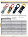
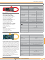
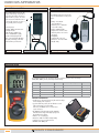
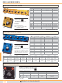
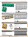
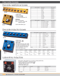
1
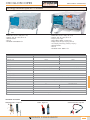
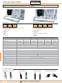
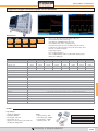
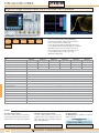
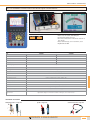
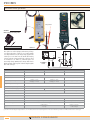
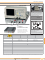
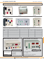
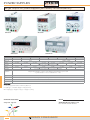
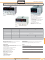
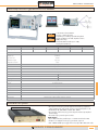
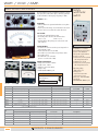
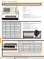
MEASURING APPARATUS
Oscilloscopes & probes
PAGES 211 - 218
Power supplies
PAGES 219 - 221
Generators
PAGES 222 - 223
Multimeters
PAGES 224 - 226
Clamps
PAGES 227 - 231
Wattmeters - Volt - Amp
PAGES 232 - 237
Various apparatus
PAGES 238 - 243
Decade boxes
PAGES 244 - 245
OSCILLOSCOPES
MEASURING APPARATUS
Analog oscilloscopes 20 to 30MHz
620
630FC
• Cathode tube screen 8 x 10 div (1div = 1cm)
• Magnifier: 100 – 50 – 20 ns/div non cal
• Wehnelt modulation
• XY mode
• CEI1010 CL1 CATII 300Vrms Pol2
REF.
• Cathode tube screen 8 x 10 div (1 div = 1cm)
• Magnifier: 100 – 50 – 20 ns/div non cal
• Frequency meter 5 digits
• Ranges 50Hz to 30MHz – sensitivity 2 mV
• Display Volt/div, Time/div, Frequency, XY mode
• Screen display: vertical range, Time base, Frequency
• Wehnelt modulation
• XY mode
• CEI1010 CL1 CAT II 300Vrms Pol2
620
630FC
2
2
Bandwidth -3dB
20MHz
30MHz
Rise time
17.5ns
Channels
11.7ns
Input impedance
Sensitivity
Magnifying control
1mΩ / 25pF
5mV to 5V/div (10 pos)
1mV to 5V/div (12 pos)
x 5 up to 1mV/div
1mV/div
Coupling
AC - DC - Ground
Max input voltage
400Vcc
Operating modes
CH1 - CH2 - CH1 & CH2 (ALT & CHOP)
Sum & difference / XY mode
CH1 ± CH2 / XY
Time base / accuracy
20 steps: 200ns to 0,5s/div / 3%
Synchronisation
Autoset
Power source
Auto - Normal - TV
no
Time base autoset
100 - 120 - 230VAC 70VA
115 - 230VAC
Dimensions
310 x 150 x 455mm
Weight
Supplied with
8.2kg
2 probes 10/1 and 1/1 0 à 60MHz - User’s manual
ADDITIONAL ACCESSORIES
Differential probes - Page 216
Probes - Pages 218
PRODUCTS 2 YEARS GUARANTEE
Coaxial accessories - Page 255
211
OSCILLOSCOPES
Digital storage oscilloscopes 50 to 150MHz
GDS1000-U serie
USB
GDS1000A-U serie
PC
software
Labview
Driver
USB
Labview
Driver
PictBridge
• Color screen TFT LCD - backlight - Vision 45 ° - 234 x 320 points
• save/recall: 15 waveforms and 15 setups
• GO – NO GO functions
• ΔV ΔT ΔF cursors
• Data logger
• Assistant for test probes x0.1 to x2000
• HELP key
• Multilangage
• Color screen TFT LCD - backlight - Vision 45 ° - 234 x 320 points
• save/recall: 15 waveforms and 15 setups
• GO – NO GO functions
• ΔV ΔT cursors
• Data logger
• HELP key
• Multilangage
REF.
PC
software
GDS1052-U
GDS1072-U
GDS1102-U
GDS1072A-U
GDS1102A-U
GDS1152A-U
2
2
2
2
2
2
50MHz
70MHz
100MHz
70MHz
100MHz
150MHz
Rise time
7ns
5ns
3,5ns
5ns
3,5ns
2,3ns
Sampling rate
250MSa/s real time, 25GSa/s equivalent time
1GSa/s real time, 25GSa/s equivalent time
4.000 points
2.000.000 points
Channels
Bandwidth -3dB
Record length by channel
Vertical resolution
8 bits
Sensitivity / Accuracy
2mV/div to 10V/div increment 1 - 2 - 5 / 3%
Time base / Accuracy
1ns/div to 50s/div increment 1 - 2 - 5 / 0,01%
Modes
Auto - Normal - Single - Edge - Pulse - Width - TV - (↑↓ 1000A-U series only)
Math functions - FFT
+ - FFT, XY
+ - x FFT, FFTrms, Zoom FFT, XY (dephas. 3%)
Auto measurements
19
27
Autoset
yes (deactivation possible)
USB device
USB1.1 & USB2.0 full speed compatible
Power source
100 - 240VAC
Dimensions
310 x 142 x 140mm
Weight
2.5kg
Supplied with
Software on CD - User’s manual
ADDITIONAL ACCESSORIES
Differential probes - Pages 216
212
Probes - Pages 218
Clamps - Pages 228
PRODUCTS 2 YEARS GUARANTEE
Coaxial accessories - Page 255
MEASURING APPARATUS
Digital storage oscilloscopes 70 to 300MHz
GDS2000A serie
USB
PC
software
Labview
Driver
PictBridge
full speed
GPIB
(option)
Ethernet
(option)
LAN
(option)
VGA
(option)
REF.
Channels
Bandwidth -3dB
Rise time
RS-232
• Colour screen 20cm TFT high resolution (800 x 600 points)
• Save/recall: 24 waveforms and 20 setups
• Fast update rate of 80,000 waveform per second
• Curve plotting: points, vectors , variable persistence
• Acquisition by segments at your choice (2048 possible observations)
• Search function of the wave form by criteria in the entire memory. Zoom.
• XY mode : 2 simultaneous displays
• 6 digits frequencymeter
• 8 or 16 logic inputs (option)
• 8 or 16 additional chanels, either 12 or 20 with time chanels (option)
• HELP touch / Multilangage
GDS2072A
GDS2102A
GDS2202A
GDS2302A
GDS2074A
GDS2104A
GDS2204A
GDS2304A
2
2
2
2
4
4
4
4
70MHz
100MHz
200MHz
300MHz
70MHz
100MHz
200MHz
300MHz
5ns
3,5ns
1,75ns
1,17ns
5ns
3,5ns
1,75ns
1,17ns
Sampling rate
2GSa/s real time, 100GSa/s equivalent time
Record length by channel
2.000.000 points
Vertical resolution
8 bits
Sensitivity
1mV to 10V/div
Time base
10ns to 10s/div
Modes
Auto (mode ROLL) - Normal - Single - Front - TV - Pulse width - Video - Runt - Rise & Fall - Alternate
Math functions - FFT
+ - x ÷ d/dt, ∫dt, √, FFT, FFTrms, ZOOM FFT
Auto measurements
36
Autoset
USB device
yes
USB - RS232 - LAN (in option) - VGA (in option) - PictBridge (GPIB in option)
Power source
100 to 240VAC - 48 to 63Hz
Dimensions
380 x 220 x 145mm
Weight
Supplied with
4.2kg
Labview driver - Complete software - User’s manual
OPTIONS
Logic analyzer
• Sample rate : 500MSa/s
• Bandwidth : 200MHz
• Record length : 2MSa max
• Input channels 16 / 8
• Triggering on 2 fronts, pattern, pulse, width, serie
BUS (I2C, SPI, UART) parallel.
Range
• Max input voltage : ±40V
• Mini voltage swing : ±500mV
• Input impedance : 100KΩ
• Vertical resolution : 1 bit
PRODUCTS 2 YEARS GUARANTEE
ref. DS2-16LA 16 channels
ref. DS2-8LA 8 channels
ref. DS2-GPIB
213
OSCILLOSCOPES
Digital storage oscilloscopes 2 & 4 channels 150 to 350MHz
Split screen
GDS3000 serie
USB
PC
high speed
software
Labview
Driver
PictBridge
• Color screen 20cm TFT high resolution 800x600pixels
• Internal memory 64Mbits - 25kpts for each input channel
• Save / Recall 24 waveforms and 20 setups
• Screen split to show both the standard signal and his zoom
• Screen split with independant setting and display for each channel
• Adjustable persistence for less frequently occurred signal
• Autoset and Autoranges, automatic measurements, cursors
• 3 input impedance selections: 50Ω - 75Ω - 1MΩ
• Online help multilanguages
VGA
output
GPIB
(option)
REF.
GDS3152
Channels
Bandwidth -3dB
Rise time
GDS3252
GDS3352
GDS3154
GDS3354
2
2
2
4
4
4
150MHz
250MHz
350MHz
150MHz
250MHz
350MHz
2,3ns
1,4ns
1s
2,3ns
1,4ns
1s
Sampling rate
2,5GSa/s to 5GSa/s (100GSa/s equivalent time)
Record length by channel
25.000 points
Vertical resolution
8 bits
Sensitivity
2mV to 5V/div
Time base
1ns to 100s/div
Modes
GDS3254
Auto (mode ROLL) - Normal - Single - Front - Pulse - Width - Video - Runt - Rise & fall - Alternate
Math functions - FFT
+ - x ÷ FFT, FFTrms, FFT, amplitude spectral, RMS, dBVrms, FFt window, Hamming, Hanning,Blackman
Auto measurements
28
Autoset
yes
Interfaces
USB - RS232 - LAN - VGA - PictBridge (GPIB in option)
Power source
100 to 240VAC - 48 to 63Hz
Dimensions
400 x 200 x 130mm
Weight
4kg
Supplied with
Driver LabView - Software - User’s manual
OPTIONS
Serial BUS analysis software
The serial bus analysis software has full analysis
tools for triggering and decoding commonly used
serial bus interfaces, including I2C, SPI and UART.
ref. DS3SBD
214
Electrical network analysis software
It measures: VRMS, peak Vfactor, frequency, Irms,
peak Ifactor, active, reactive, apparent power, cos φ,
phase angle. Harmonics: Freq., Amplit., Amplit.rms,
phase, THD-F, THD-R, RMS
ref. DS3PWR
PRODUCTS 2 YEARS GUARANTEE
Standard Interfaces
One GPIB USB adapter is available as an option for
interface conversion
ref. GUG001
MEASURING APPARATUS
20 to 60MHz hand-held oscilloscope multimeter
RS-232
REF.
Channels
• Colour screen 75 x 56mm, 640 x 480 points
• Save/Recall 4 waveforms & 4 setup
• Zoom on the window. Choise of the window and zoom as
far as 5ns/div
• Autoset and Autoranges, auto. measurements, cursors
• Digital multimeter TRMS
USB
1022MN
2062MN
2
2
Bandwidth -3dB
20MHz
60MHz
Rise time
17.5ns
5.8ns
Sampling rate
100MSa/s
250MSa/s
Record length by channel
6.000 points
Vertical resolution
8 bits
Sensitivity
Modes
5mV to 5V/div in séquence 1 - 2 - 5
Auto., normal, single, edge ↑↓, video
Fonctions Math - FFT
± x ÷ FFT
Mesures automatiques
20
Measurement cursors
V1/zero V2/zero ΔV T1/zero T2/zero ΔT
Fonctions Autoset
yes
Interfaces
USB - RS232
Multimeter
VDC - VAC - IDC - IAC - RΩ - CµF - Test diodes
Power source
Battery Li-ion. Operate time 6 hours.
Dimensions / Weight
Supplied with
180 x 113 x 40mm / 700g
2 oscilloscope probesx1 & x10 / 2 test leads for multimeter / Mains adaptor / USB lead
Capacitance adaptor / Shunt 20A / Software / Transport case / User’s manual.
ADDITIONAL ACCESSORIES
Differential probes - Pages 216
probes - Pages 218
PRODUCTS 2 YEARS GUARANTEE
Coaxial accessories - Page 255
215
PROBES
Differentials probes
Mains adapter
supplied
Safety connectors
OPTIONS
Mains adapter for ISOL probes
ref. ADA6
ISOL-710
DP25
OSCILLOSCOPE
These probes are used for displaying and measuring of dangerous voltages with a Class I oscilloscope, in accordance with the
user safety standards. In fact, the image voltage applied to the
oscilloscope is no more than a few volts. On the other hand, by
using two probes the voltages applied to the oscilloscope inputs
are isolated from one another. So, differential probes can
measure high voltages (DP50) and/or voltages which relate to
different potentials, without any risk of short-circuiting through the
base of the oscilloscope.
REF.
Channel
Y1
MAINS
RÉSEAU
Measurable input voltage DC + AC
SONDES
DIFFERENTIAL
DIFFERENTIELLES
PROBES
ISOL-710
ISOL-720
DP25
1
1
1
DC to 25MHz
1/10 and 1/100
1/20 and 1/200
1/20 1/50 1/200
140Vpp on 1/10
1400Vpp on 1/100
280Vpp on 1/20
2000Vpp on 1/200
respect. 200Vpp / 500Vpp / 1400Vpp
Output voltage to oscilloscope
+/- 7V
Max. differential input voltage
Max common mode voltage (1)
Input impedance
M
+
- 7V max
Bandwidth to -3dB
Attenuation ratio
Y2
+/- 5V
1000Vrms
500Vrms
1000Vrms
4 MΩ / 5pF
4 MΩ / 1,2pF
Rise time
14 ns
Accuracy
2%
CEI1010 cat III Pol 2
600Vrms
1000Vrms
600Vrms
Battery (4 x LR6) and mains adapter
Mains adapter 230V 50/60Hz
Dimensions / Weight
158 x 62 x 20mm / 290g
210 x 58 x 35mm / 200g
Supplied accessories
Rubber jacket
+ test clip
Holster + test clips
+ mains adapter
Power source
(1) Common mode voltage: voltage between, on one hand, the interconnected inputs and on the other hand the ground or the BNC terminal on the oscilloscope
216
PRODUCTS 2 YEARS GUARANTEE
MEASURING APPARATUS
RMS CONVERTER
FOR CURRENT PROBES
Oscilloscope not supplied
ref. ADA-SONDE
ADA-SONDE converts any complex signal, even
with superimposed continuous component, into a
continuous signal image of the RMS value of the
input signal. Connects between a current or
voltage probe and an oscilloscope.
Accuracy*
1%
10%
Bandwidth
DC to 30KHz
DC to 100KHz
* For input sine-wave signal 100mV
I tore
t
ISOL-712
Vs
COMPACT
DIFFERENTIALS PROBES
t
Gain is 1
Thus if Ve = 1Vrms , Vs = 1VDC
Max input voltage: ± 1V
Ergonomic solutions of differential probes,
supplied from mains, with 2 or 4 channels
according the models. The housing is strong
enough to put an oscilloscope on top.
REF.
Channel
ISOL712
ISOL714
ISOL722
ISOL724
2
4
2
4
Bandwidth to -3dB
Attenuation ratio
Measurable input voltage DC + AC
DC to 25MHz
1/10 and 1/100
1/20 and 1/200
140Vpp on 1/10
1400Vpp on 1/100
280Vpp on 1/20
2000Vpp on 1/200
Output voltage to oscilloscope
+/- 7V
Max. differential input voltage
1000Vrms
Max common mode voltage (1)
Input impedance
500Vrms
1000Vrms
4 MΩ / 5pF
Rise time
14 ns
Accuracy
2%
CEI1010 cat III Pol 2
Power source
Supplied with mains adapter and 2 BNC cables
1000Vrms
Mains 230V
Dimensions / Weight
300 X 65 X 350mm
Supplied accessories
2 or 4 BNC leads (25cm)
(1) Common mode voltage: voltage between, on the one hand, the interconnected inputs and on the other hand the ground or the BNC terminal on the oscilloscope
PRODUCTS 2 YEARS GUARANTEE
217
PROBES
True RMS DC and AC low current probes
Ø21
Ø8
VA15
Ø9
Ø9
DCA60
PSY500
PSY510
These probes are used with an oscilloscope, a multimeter or a recording instrument. They deliver a secondary image voltage of the primary current (a few dozen millivolts),
thereby allowing the user to take measurements in complete safety and without having to switch off the power to the circuit. The Hall sensor fitted in them can detect a DC component overlaid onto the AC component. When used with a true RMS multimeter, these probes will provide a true RMS current measurement.
REF.
VA15
DCA60
PSY500
PSY510
Output voltage /
Input current
100mV/A range 4A
10mV/A range 30A
1000mV/A range 400mA AC only.
100mV/A range 20A
10mV/A range 60A
200mV/A range 5A
20mV/A range 50A
1 V / A range 4A
0,1V / A range 40A
Ranges DC + AC
4A & 30A
20A & 60A
5A & 50A
4 & 40 A
Range AC only
400mA AC
Accuracy
Diameter
of the jaws
Power source
-
1% DC ~ 1kHz
21mm
8mm
9mm
battery : 2 x LR6
battery : 1 x 6LR61
Mains or battery 1LR61 (9V)
CEI100
2% DC ~ 50Hz
3% 50Hz ~ 100kHz
5% 100kHz ~ 120kHz
CATIII 300Veff pol2
2 safety leads
1 BNC adapter
1 BNC adapter
1 BNC lead
1 BNC adapter
1 mains adapter
Supplied with
218
2% DC to 80Hz
3% 80Hz to 180kHz
5% 180kHz to 270kHz
6% 270kHz to 350khz
2% 40Hz ~ 2kHz
4% 2kHz ~ 10kHz
6% 10kHz ~ 40kHz
PRODUCTS 2 YEARS GUARANTEE
1 BNC lead
1 BNC adapter
1 mains adapter
POWER SUPPLIES
MEASURING APPARATUS
Multi-outputs power supplies
AL841B
ALF1501D
AL890NX
AM061205
AL843A
AM061210
Complete range of DC or AC&DC power supplies, fixed or variable, fully protected for various type of use in laboratory.
Ref
DC OUTPUTS
AC OUTPUTS
Power
Informations
3V / 4,5V / 6V / 7,5V / 9V / 12V - 1A
-
12 W
6 selectable voltage
AL890NX
±15v / 0,5mA
-
15 W
symmetric
ALF1501D
±15V 1A or 24V 1 A or 12V 2,5A
-
30 W
±15V (Aj. ±10 à ±15V)
AL841B
AL843A
6V, 12V / 10A or 24V / 5A
6V, 12V / 10A or 24V / 5A
120 W
AC & DC simultaneous
AM061205
6V , 12V / 5A
6V , 12V / 5A
120 W
AC & DC simultaneous
AM061210
6V / 20A , 12V / 10A
6V / 20A , 12V / 10A
120 W
AC & DC simultaneous
STABILIZED POWER SUPPLY, RS232, LABVIEW, USB*
CURRENT GENERATOR AC/DC POWER SUPPLY
Réf. ALR3002M
Réf. AL991S
*USB OPTION
Set comprising an USB/RS232
adapter + null modem lead
Réf. USBRS232
• ± 0-15V / 1A or 0-30V / 1A and
2-5,5V / 3A and -15 - 0 - +15V / 200mA
• Power : 48 Watts
• Display: Digital
• Interface: RS-232
• Software: Windows95 minium, LabVIEW
• 0 to 5V, 6V, 12V or 30V / 0 - 25 mA, 250 mA or 2,5A DC
• 6V or 12V or 24V / 5 A AC
• Power : 120 Watts
Reading of voltages and currents on separate displays.
AC & DC voltages available at the same time.
PRODUCTS 2 YEARS GUARANTEE
219
POWER SUPPLIES
Single output DC power supplies (with safety terminals Ø4mm)
GPS3030A
GPS3030D
GPR3510HD
REF.
Display type
GPS3030A
GPR30H10A
GPS3030D
TYPE A
GPS1850D
GPR3060D
GPR3510HD
0 to 30V
GPR30H10A
TYPE A
90VA
0 to 30V
GPR6030D
TYPE DD
180VA à 1000VA
0 to 18V
Adjustable
Current
GPS3030DD
TYPE D
Power
Voltage
GPS3030DD
0 to 30V
0 to 30V
0 to 35V
0 to 60V
0 to 300V
0 à 10A
0 à 3A
0 à 1A
by 2 knobs coarse and fine from 0 to Vmax
0 à 3A
0 à 3A
0 à 5A
0 à 3A
0 à 6A
Adjustable
by 2 knobs coarse and fine from 0 to I max or 0 to Imax/2
Regulation
Output voltage variation : < 0,01% + 3mV - Output current variation < 0,2% + 3mA
by mains variation of 15% or load variation 0 ~ 100%
Ripple & noise
Protection
0.5mVrms
Electronic by current limitation against overload and short circuit
Power source
Mains 120-240V - 50/60Hz
Supplied with
Power lead and user’s manual
DISPLAY TYPE
A : analogue type (with voltmeter & ammeter) Class 2,5%
D : digital type. (1 switchable display for Voltage/current)
DD : 2 digital type (1 display for voltage + 1 display for current)
ADDITIONAL ACCESSORIES
OPTION
Safety leads - Page 254
GREEN/YELLOW male earthing socket
Put a «-M» at the end of the references
220
PRODUCTS 2 YEARS GUARANTEE
MEASURING APPARATUS
Multi output power supplies (with safety terminals Ø4mm)
SPD3606
GPD3303 - WITH USB CONNECTOR
High resolution 1mV – 1mA,
can be remotely controlled via the USB connection.
Adjustable by numeric keypad or encoder
• Accuracy of programming: voltage 0.03%+10dgt,
current 0.3%+10dgt
• Accuracy of reading: voltage 0.03%+10dgt,
current 0.3%+10dgt
Saving of 4 different configurations
High-resolution display: 30,000V – 3,000 A.
Labview driver.
GPS3303
REF.
SPD3606
INDEPENDENT 1
2 x 0 to 30V - 2 x 0 to 6A
INDEPENDENT 2
GPS2303
GPS3303
2 x 0 to 30V - 2 x 0 to 3A
2 x 0 to 60V - 2 x 0 to 3A
-
SERIAL 1
0 to 60V - 0 to 6A
0 to 60V - 0 to 3A
SERIAL 2
0 to 120V - 0 to 3A
-
PARALLELE
0 to 30V - 0 to 12A
AUXILIARY
0,1 to 5V - 3A
Dims
255 x 145 x 265mm
Weight
GPD3303
0 to 30V - 0 to 6A
-
5V - 3A
255 x 145 x 265mm
6kg
2,5 - 3,3 - 5V - 3A
210 x 130 x 265mm
8kg
Power source
Mains 120-240V - 50/60Hz
Multiple power supplies consist of two or three power sources which are
galvanically isolated from each other.
• 2 adjustable power supplies with rectangular features
PROTECTIVE DEVICES
All of the outputs are protected against short-circuits, even those lasting a long time.
In this case, the power supply will automatically switch to a current source.
AC POWER SOURCES
• Voltage can be adjusted progressively from 0 to Vmax.
• Voltage variation: <0.01% + 3mV or <0.02% + 3mA for 100% load variation
or 15% mains variation.
• Current can be adjusted progressively from 0 to Imax.
• Regulation: background noise <1mVrms.
• Slave repeater error: <0.5% of the master voltage.
• Response time: 0 to Vmax. = 0.1ms.
DISPLAYS
Digital: 3 digits 1/2 LED 13mm. 0.5%
AUXILIARY SOURCE (except for GPS2303)
• Auxiliary fixed voltage: 5V, 3A rating
• Voltage regulation:
<10mV for 100% charge variation
<5mV for 15% mains variation
• Background noise <2mVrms
THREE OPERATING MODES
Independent mode
Both power supplies are completely independent from each other.
Tracking Series mode
Allow the two power supplies to be used as a 0 to double rating voltage supply.
Tracking Parallel mode
Allow the two power supplies to be used as a 0 to double rating current supply.
PRODUCTS 2 YEARS GUARANTEE
221
GENERATORS
Function generators 2 & 3MHz with or without frequency counter
GFG8219 - 3MHz - AM - FM
GFG8215 - 3MHz
SFG1013 - 3MHz - DDS
GFG8020G - 2,2MHz
REF.
GFG8219
Waveforms
GFG8215
0,01Hz to 3,3 MHz - 7 ranges
Output voltage
0,01Hz to 2,2 MHz - 7 ranges
2 : -20dB ±1dB
Offset
1 : -40dB
Continuously variable from -10V to +10V into 600Ω
variable from 10% to 90%
Calibrate to 50%
variable from 25% to 75%
Calibrate to 50%
≥ 3Vpp . Rise time ≤25ns. Load : 20 TTL gates
TTL output
CMOS output
Adjust 4Vcc to 14,5Vpp. Rise time < 120ns
Sinus
1% from 0,3Hz to 200kHz.
Triangle
no
1% from 0,2Hz to 200kHz.
Linear and symetry > 98% from 0.1Hz to 100kHz
Square
>-55dBc 0,1Hz to 200kHz.
>95% after
Rise time < 100ns (120ns for GFG8020G) - Symétry : 2% from 0,2Hz to 100kHz (5% for SFG1013)
Input impedance 10kΩ - Δf/f = 1/10 for a voltage step of 10VDC
VCF
Δf/f variable from 1/1 to 1/100
Depth of modulation
0 to 100 %
yes
Frequency ranges
Internal 0,01 Hz to 3,3 MHz
External 0,01 Hz
to 150 MHz / 6digits
Protection
CEI1010
Power source
Dimensions
Weight
no
no
no
no
no
no
no
no
no
no
no
internal : 0,01 Hz
to 2,2MHz / 4digits
internal : 0,1 Hz
o 3MHz / 6digits
against overload
CATII 250Vrms pol2
CATII 300Vrms pol2
115 - 230 VAC 50/60Hz
120 - 230 VAC 50/60Hz
115 - 230 VAC 50/60Hz
251 x 91 mm. Depth 291mm
230 x 95 mm. Depth 280mm
251 x 91 mm. Depth 291mm
2kg
2kg
2,1kg
ADDITIONAL ACCESSORIES
Coaxial accessories - Page 255
222
0,1Hz to 3 MHz - 7 ranges
1 : -20dB ±1dB
variable from 20% to 80%
Calibrate to 50%
Duty
Frequency modulation
sine - square - pulse - TTL
20 Vpp on 600Ω 10Vpp on 50Ω
Attenuators
Amplitude modulation
SFG1013
sine - square - triangle - pulse - TTL - CMOS - (GFG8219 only : AM - FM)
Frequency
Internal sweep
GFG8020G
PRODUCTS 2 YEARS GUARANTEE
MEASURING APPARATUS
Arbitrary function generators 5 to 25MHz
11cm TFT LCD resolution 480x272
Frequency + voltage and settings.
Programming of an arbitrary signal with the keyboard.
Sample rate 20MSa/s and 10 bits amplitude resolution.
4000 points memory.
AM FM FSK SWEEP Modulation (série 2100).
Frequencymeter (2100 serie).
USB
PC
software
REF.
Frequency range
AFG2105
AFG2112
AFG2125
AFG2005
AFG2012
AFG2025
0,1Hz à 5MHz
0,1Hz à 12MHz
0,1Hz à 25MHz
0,1Hz à 5MHz
0,1Hz à 12MHz
0,1Hz à 25MHz
Waveforms
Sinus, Carré, Triangle, Rampe, Bruit et arbitraire
Arbitrary functions
- Sample rate
- Repetition rate
- Waveform lenght
- Amplitude resolution
20 Mech/s
10 MHz
4 kpoints
10 bits
Amplitude
2mV à 20Vcc (à vide) - 10Vcc sur 50Ω
Rise / Fall time
< 25ns avec l’amplitude maximale sur 50Ω
Offset ranges
± 10V (à vide) / ± 5V sur 50Ω
Rise time
< 25ns (50Ω)
AM / FM Modulation
FSK Modulation
Frequency
Sweeping
Memory
oui
non
oui
non
5Hz à 150MHz
non
yes
10 storage memory
TTL output
yes
Interface
USB
Power source
100 - 240VAC - 50/60Hz - 25VA
Dimensions
266 x 107mm. Depth 293mm.
Weight
3.2kg
Supplied with
Arbitrary waves editing software and user’s manual
Follower amplifier
REF. AS150
• The output of a low frequency generator applied to the AS150 input, amplifies the
voltage until 80V peak to peak, and the current up to 7A with an impedance ≥ 4Ω.
• Bandwidth at 0.1dB: 20Hz-20kHz. (at 0.7dB: 10Hz - 50kHz)
• The output level of the low frequency generator adjusts the AS150 output amplitude
from 0 to 80Vpp.
• The AS150 output is protected against overloads.
OTHER FEATURES
• Input on BNC terminal Two parallel outputs: on 2 ∅4mm terminals and on BNC
• AS150 does not amplify the low frequency generator DC component
• 100 – 240VAC 50-60Hz power supply. Dimensions/weight: 500 x 300 x 65mm 4.7kg
PRODUCTS 2 YEARS GUARANTEE
223
MULTIMETERS
Auto ranging multimeters
ST9929
ST9919
Range of reliable and robust automatic multimeters.
Sturdy ABS housing, protected by a shock resistant soft
moulded holster, waterproof (IP67)
REF.
ST9927T
• Peak hold function. Min et Max (exept ST9915)
• Relative measurements
• Bargraph (exept ST9915)
ST9929
ST9919
Display
ST9915
40.000 points
• Hold (ST9929)
• Data recording, max 200s (ST9929)
• Auto power-off after 15min
ST9927T
ST9915
6.000 points
4.000 points
-
Converter
TRMS AC+DC
TRMS AC
TRMS AC
Bandwidth
40Hz to 10kHz
40Hz to 1kHz
40Hz to 1kHz
-
VDC
accuracy
400mV to 1000V
0,06% + 4dgt
600mV to 1000V
0,09% + 2dgt
400mV to 1000V
1,2% + 2dgt
VAC
accuracy
400mV to 1000V RMS
1% + 30dgt - 5% + 30dgt from 1kHz to 10kHz
6 to 1000V TRMS
1 to 2% +3dgt
400mV to 1000V
1,5% + 3dgt
IDC
accuracy
400µA to 10A
1% + 3dgt
600µA to 10A
1% + 3dgt
400µA to 10A
1,5% + 3dgt
IAC
accuracy
400µA to 10A RMS
1,5% + 30dgt - 5% + 30dgt from 1kHz to 10kHz
600µA to 10A TRMS
1,5% +3dgt
400µA to 10A
1,8% + 5dgt
OHM
accuracy
400Ω to 40MΩ
0,3% +4 to 9dgt
600Ω to 60MΩ
0,3% + 4dgt
400Ω to 40MΩ
1,2% + 2dgt
Farad
accuracy
40nF to 40mF
3,5% +10 to 40dgt
60nF to 1000µF
3,5% + 4dgt
4nF to 200µF
3% + 5dgt
40Hz to 10MHz
0,50%
10Hz to 40MHz
0,1% + 1dgt
10Hz to 40MHz
1,2% + 3dgt
Frequency
accuracy
Diode test
. ))))
Duty
accuracy
)
°C (type K)
accuracy
4 - 20mA
Test 0,9mA - 2,8V
Test 0,3mA - 1,5V
Ring for R < 35Ω
Ring for < 100Ω
Ring for < 150Ω
0,1% to 99,9%
1,2% + 2dgt
0,1% to 99,9%
1,2% + 2dgt
0,1% to 99,9%
1,2% + 2dgt
-50 to 1000°C
1% + 2,5°C
-45 to 750°C
3% + 5°C
-
-
-
4mA~0% ; 20mA~100%
Ranging
Auto & Manual
Protection
Power source
Dimensions / Weight
Supplied with
1 battery 9V type 6LR61
182 x 82 x 55mm / 430g
Input impedance as voltmeter: 10MΩ
224
182 x 82 x 55mm / 375g
Test leads, thermocouple, carrying case, battery, user’s manual.
PRODUCTS 2 YEARS GUARANTEE
MEASURING APPARATUS
Manual ranging multimeters
ST9905
2005DMM
Range of reliable and robust manual multimeters.
Sturdy ABS housing, protected by a shock resistant
soft moulded holster, waterproof (IP65)
REF.
TRG2106
UM2010
ST9905 - 2005DMM - TRG2106
• Auto power-off after 15min
UM2010
• Length of the scale: 90mm
• Safety sockets 4mm
ST9905
2005DMM
TRG2106
UM2010
2.000 points
2.000 points
20.000 points
Analogical
VDC
Accuracy
200mV to 1000V
0,5% + 2dgt
200mV to 1000V
0,5% + 3dgt
200mV to 1000V
0,05% + 3dgt
100mV to 1000V
1,5 %
VAC
Accuracy
200mV to 700V
1,2% + 3dgt from 50Hz to 400Hz
IDC
Accuracy
2mA to 10A (20A during 30s)
1,5% + 3 dgt (3% +10dgt/20A)
2mA to 10A (20A during 10s)
1,2% + 3 dgt (20A ±2%)
2mA to 20A
0,8% + 5dgt
50µA to 10A
1,5 %
IAC
Accuracy
2mA to 10A (20A during 30s)
2% + 3dgt (3% +10dgt/20A)
2mA to 10A (20A during 10s)
1 to 2% + 5dgt from 40Hz to 200Hz
3% à 20A
2mA to 20A
2% + 10dgt
2,5mA to 10A
2,5 %
OHM
Accuracy
200Ω to 200MΩ
1,2% + 1dgt up to 20MΩ
200Ω to 2GΩ
0,8% + 3dgt up to 2MΩ
200Ω to 200MΩ
0,2% + 3dgt up to 20MΩ
1 to 1000 kΩ
2%
Farad
Accuracy
2nF to 200µF
4% + 3dgt to 2µF
20nF to 200µF
2,5% + 20dgt up to 20µF
2nF to 200µF
4% + 10dgt
-
Henry
Accuracy
-
2mH to 20H
2,5% + 20dgt
-
-
Frequency
Accuracy
-
2kHz to 10MHz
1% + 10dgt
20kHz
1,5% + 5dgt
-
Display
Diode test
. ))))
)
°C (type K)
Accuracy
200mV to 200V from 40Hz to 400Hz
200mV to 700V
750V from 40Hz to 100Hz
0,8% + 10dgt from 50Hz to 400Hz
1,2% + 3dgt
1mADC under 2,8VDC max
Ring for R< 50Ω
Ring for R< 90Ω
Ring for R< 70Ω
Ring for R< 50Ω
-
-20 to 1000°C 1% thermocouple K
-
-
CAT III 1000V Pol 2
CAT III 1000V Pol 2
CAT III 300V Pol 2
CAT III 600V Pol 2
Ranging
Protection
Manual
Power source
Dimensions
Fuses
Supplied with
10 to 1000V
2,5 %
1 battery 9V type 6LR61
3 batteries LR6
182 x 82 x 55mm / 360g
190 x 95 x 45mm / 400g
200 x 90 x 40mm / 600g
170 x 110 x 53mm / 500g
0,2A/250V - 5x20mm - fast
20A/250V - 6,3x25mm - fast
200mA - 5 x 20 fast
20A - 5 x 20 fast
0,5A/250V - 6,3x25mm - fast
HPC 600V 1A
HPC 600V 10A
Housing, user’s manual, test lead
User’s manual, test lead
PRODUCTS 2 YEARS GUARANTEE
225
07-mesure-export_cata 09-10 24/11/14 12:00 Page226
MULTIMETRES
Multimètres de table
TRG803
• Mesures efficaces vraies RMS
- composante alternative seule
- signal composite DC + AC efficace vrai
• Mesure des valeurs min et max
• Logiciel
• Capacimètre et fréquencemètre
• Températures . Test de transistor
• Automatique et manuel
GDM8251
GDM8145G
• Mesures efficaces vraies:
- composante continue seule
- composante alternative efficace seule
- signal composite DC + AC eff. vrai
• Contrôle à distance
• Ohmmètre 2 et 4 fils
• dBm, dB, Max Min, compare, mémorise,
• Fonctions math : ax + b, 1/x, %
• Deuxième afficheur pour Hz, dB, bruit
• Option: carte scanner 16 canaux
• Mesures efficaces vraies
- composante continue seule
- composante alternative efficace seule
- signal composite DC + AC efficace vrai
REF.
Affichage
GDM8251
GDM8145G
TRG803
120.000 points
20.000 points
6.000 points
Convertisseur
Largeur de bande
TRMS AC+DC
100kHz
50kHz
100kHz
VDC
100mV à 1000V
200mV à 1200 V
600mV à 1000V
VAC
100mV à 750V
200mV à 1000 V
600mV à 1000V
IDC
10mA - 10A
200µA à 20A
600µA à 10A
IAC
10mA - 10A
200µA à 20A
600µA à 10A
100Ω à 100MΩ
200Ω à 20MΩ
600Ω à 60MΩ
-
-
6nF à 6mF
10Hz à 800kHz
-
10 Hz - 60MHz
OHM
Farad
Fréquencemètre
Test diodes . ))))
)
Température °C (type K)
Tension max : 2V
Beeper
0 à 300°C type J, K, T
Changement gamme
Interface
- 40°C - 1000°C
Automatique et Manuel
RS232 - USB
Protection
Alimentation
affiche la chute de tension
-
RS232 - USB
CEI1010 CATIII 300Veff pol2
115- 230VAC 50/60Hz
230VAC 50/60Hz
Secteur ou piles
Dimensions / Poids
267 x 107 x 350mm / 2,6kg
245 x 95 x 280mm / 2,6kg
240 x 105 x 310mm / 2,4kg
Livré avec
Logiciel PC et Driver Labview
Notice
Notice
Logiciel, Notice
226
PRODUITS
GARANTIS 2 ANS
CLAMPS
MEASURING APPARATUS
High sensitivity RMS test clamp
REF. VA21
MEASUREMENTS
ACTIVE POWER
REACTIVE POWER
ENERGY
AC VOLTAGE
AC CURRENT
LEAKAGE CURRENT
HARMONICS AC VOLTAGE
HARMONICS AC CURRENT
TOTAL HARMONIC DISTORTION
Batteries : 2 x LR6
POWER FACTOR
PHASE ANGLE
CREST FACTOR
• Auto ranging
• Auto power-off after 30min.
• Dim: 210 x 62 x 36mm. Weight: 500g
• Supplied with test leads and carrying case
SINGLE & BALANCED THREE PHASES POWER
W or VA or VAR
RANGES
KW or kVA or kVAR
0.050 ~ 9.999
10.00 ~ 99.99
100.0 ~ 999.9
1.000 ~ 9.999
10.00 ~ 99.99
RESOLUTION
0,001
0,01
0,1
0,001
0,01
ACCURACY★
1%
1%
1%
1%
1%
AC CURRENT RMS
in mA
RANGES
in A
0.30 ~ 60.00
60.00 ~ 600.0
0.030 ~ 3.000
3.00 ~ 30.00
30.00 ~ 50.00
0,01
0,1
0,001
0,01
0,01
0,5%
0,5%
0,5%
0,5%
1%
RESOLUTION
★
ACCURACY
AC VOLTAGE RMS
RANGES
3,0 to 250,0VAC
250 to 600VAC
Accuracy : 0,5% ★
★
Bandwith 50Hz ~ 5kHz Accuracy 5% from 50Hz to 10kHz
HARMONICS of AC VOLTAGE in % or in VAC order 1 to 99
ORDER
RESOLUTION in %
RESOLUTION in VAC
Accuracy
1 to 99
0,1%
0,1 VAC
1 to 35% as per order
HARMONICS of AC INTENSITY in % or in IAC order 1 to 99
in mA
RANGES
in A
0.10 ~ 60.00
60.00 ~ 600.0
0.600 ~ 3.000
3.00 ~ 30.00
30.00 ~ 50.00
RESOLUTION in mA - A
0,01
0,1
0,001
0,01
0,01
RESOLUTION in %
0,1%
0,1%
0,1%
0,1%
0,1%
ACCURACY as per order
1-10: 1% + 7dgt
11-20: 5% + 7dgt
21-50: 15% + 7dgt
51-99: 35% + 7dgt
OTHER FUNCTIONS
RANGES
RESOLUTION
ACCURACY
0.000 ~ 1.000
0.001
± 0.04
-180 ~ 180°
0.1°
± 2°
THD * 1 to 99 order
0.0 ~ 999.9%
0.10%
2 ~ 20% **
CREST FACTOR
1.00 ~ 99.99
0.01
5% + 30 dgt
POWER FACTOR
PHASE ANGLE
ENERGY
*THD total harmonics distortion
mWh Wh et kWh SINGLE & BALANCED 3-PHASE
** according the rate
PRODUCTS 2 YEARS GUARANTEE
227
CLAMPS
AC, DC, AC&DC clamps
PWM
MS330 - AC
MS332 - AC & DC
• Peak hold function Max
• Auto power off after 15mn
PWM
MS3347 - DC & TRMS AC
• Duty 0,5 ~ 99%
• Auto power off after 10mn
PWM
PWM
PWM
MS337
• Peak hold function Min & Max
• Auto power off after 20mn
• Bargraph
MS223
• Auto power off after 25mn
• Recopy output 10mV/A 20kHz
• Back lighting of the screen
• Peak hold function Min & Max
• Auto power off after 10mn
• Recopy output 10mV/A 20kHz
The clamps with the PWM logo are compatible with PWM variator.
REF.
MS330
Display
MS332
MS3347
2.000 points
Converter
MS337
AC
AC & DC
Bandwidth
10.000 points
DC & TRMS AC
50 to 100Hz
Opening of the jaws
25mm
29mm
2 to 600V
4 to 600VDC / 400mV to 600VAC
2 to 400A AC only
40 to 400A
VDC / VAC
IDC / IAC
MS223
4.000 points
AC & DC
AC & DC
50Hz to 500Hz
50Hz to 20kHz
35mm
12mm
400mV to 600V
600V
40 to 1000A
4 to 80A
9,999 to 99,99 A
OHM
200Ω to 20MΩ
4Ω to 40MΩ
9,999 kΩ
Farad
-
40nF to 100µF
4nF to 40mF
40nF to 100µF
-
Frequencymeter
-
5Hz to 150kHz
0 to 4,000 kHz
5Hz to 10MHz
-
Diode test
400Ω to 40MΩ
0,4mA - 1,5VDC test
. ))))
)
Ring for R< 50 Ω
Ring for R< 150 Ω
-
-
°C
Ranging
0,3mA - 1,5VDC test
Auto & Manual
Ring for R< 35 Ω
-40°C to 1000°C
Auto
Protection
2 batteries LR03
205 x 70 x 37 mm / 200g
Supplied with
1 battery 6LR61
200 x 50 x 35 mm / 200g
230 x 80 x 50 mm / 300g
Ring for R< 100Ω
-
-
Auto & Manual
Auto
Oscilloscopes - Pages 221 - 215
2 batteries LR03
210 x 70 x 37mm / 200g
Test lead, soft carry case, batteries
ADDITIONAL ACCESSORIES
228
-
Ring for R< 150Ω
CATIII 600Vrms pol2
Power source
Dimensions / Weight
-
Coaxial leads - Pages 255
PRODUCTS 2 YEARS GUARANTEE
202 x 70 x 34 mm / 180g
MEASURING APPARATUS
High sensitivity clamps
UT251A
ST9809
ULTRA SENSITIVE CLAMP
• Allows to measure AC current of some µA (50/60Hz)
• A memory function: storage of 99 measurements
• PEAK measurement
• Autoranging: 0,001mA to 60,00A
• Resolution 1 µA, accuracy ± 1,5% +5dgt
• Allows to measure a current difference between two conductors (differential).
LEACKAGE CURRENT CLAMP
• Allows to measure AC currents of some hundred µA
• Peak hold function: max & min
• Auto power off after 30min
• Bargraph
REF.
UT251A
ST9809
10.000 points
4.000 points
IAC (accuracy)
0,001mA to 60A, automatic ±1,5%
40mA to 100A (2,5% + 15dgt)
VAC (accuracy)
-
400V (2% + 4dgt)
Display
OHM (accuracy)
Protection
-
400Ω (1% + 2dgt)
CEI1010 CAT III 600Vrms Pol2
CEI1010 CAT III 300V
Power source
1 battery 6LR61
Dimensions / Weight
Supplied with
175 x 70 x 38mm / 120g
210 x 62 x 35mm / 200g
Acquisition software, specific USB cable, briefcase.
Test leads, soft carry case
RMS converter for MS223 clamp
I tore
t
Vs
ADA-RMS plugs on clamp MS223 (see page 228).
The ADA-RMS output supplies DC voltage image of the rms current flowing
in the clamp core, even for current with superimposed continuous component.
The output voltage is viewed with the oscilloscope.
• Output voltage: 10mV/A
• Accuracy of the MS223+ADA-RMS system: 5% of DC at 20kHz
• Automatic shutdown
• Power supply: 9V pressure battery.
• Supplied with BNC cable
t
ref. ADA-RMS
only the converter
PRODUCTS 2 YEARS GUARANTEE
229
PINCES
Pinces multifonctions
MLI
MLI
MLI
MLI
MS232
ST3348
ST3353
VA6600
• Puissance active RMS AC + DC
• Capture de la valeur Max
• Arrêt automatique à 30mn
• Puissance active RMS AC + DC
• Fréquence
• V et I TRMS en AC
• Arrêt automatique à 30mn
• Rétroéclairage
• Double affichage (W & VA, W & ϕ etc…)
• Vrms – Irms - W - VA - VAR - cosϕ - kWh
• Mono et triphasé (3 & 4 fils)
• TRMS en IAC & VAC
• Mesure de crêtes Min et Max
• Interface USB + logiciel fourni
• Mémoire (99 mesures)
• Arrêt automatique à 30mn
• Ecran LCD 4 digits et bargraph (éclairé)
• RMS AC + DC
• double afficheur
• U et I , U et Hz , I et Hz , W et cosϕ , VA et VAR.
• Puissances actives, réactives, apparentes
• Mémoire : stockage de 4 mesures
MLI
Les pinces marquées de ce logo sont compatibles
avec un variateur MLI
REF.
Affichage
MS232
ST3348
ST3353
VA6600
10.000 points
4.000 points
10.000 points
2 x 4 chiffres
RMS AC
RMS AC+DC
50 à 60Hz
50 à 200Hz
DC à 400Hz
Ø 53mm
Ø 55mm
Convertisseur
Largeur de bande
DC + TRMS AC
50 à 500Hz
Diamètre des mâchoires
Ø 30mm
VDC
600V (1% + 5dgt)
400mV à 600V (1,5% + 3dgt)
-
-
VAC
600V (1% + 5dgt de 50 à 500Hz)
400mV à 600V (1,5% + 3dgt)
15 à 750V (1,2% + 5dgt)
VAC+VDC 200 à 600V 2%+5dgt
IDC
600A (1,5% + 5dgt)
1000 A (1,8% + 5dgt)
-
-
IAC
600A (1,5% + 5dgt de 50 à 500Hz)
1000 A (1,8% + 5dgt)
40 à 1000A (2% + 5dgt)
IAC+IDC 200 à 2000A 2%+5dgt
WDC
100 à 360kW
40 à 240kW
-
-
WAC
100 à 360kW RMS
40 à 240kW RMS
0,6 à 750kW
99,99 à 1200kW 2%+5dgt
VA
-
-
0,6 à 750kVA (3% + 5dgt)
99,99 à 1200kVA 2%+5dgt
VAR
-
-
0,6 à 750kVAR (4% + 5dgt)
99,99 à 1200kVAR 2%+5dgt
-
OHM
10 000Ω (1% + 5dgt)
400Ω à 40MΩ (1,5% + 2dgt)
-
Fréquencemètre
-
5Hz à 100kHz
20 à 200Hz
-
Energie kWh
-
-
1 à 9999kWh (3% + 2dgt)
-
Test diodes
-
. ))))
Cosφ
Changement gamme
Alimentation
Livré avec
230
-
-
-
0,3 à 1Capacitif ou inductif
(0,02 + 2 dgt)
Automatique
0,999 2%+5dgt
CATIV 600Veff pol2
CATIII 600Veff pol2
Automatique
Protection
Dimensions / Poids
Test sous 0,3mA
sonne pour R< 100Ω
)
Automatique et Manuel
CATIII 600Veff pol2
Automatique
2 piles LR03
1 pile 6LR61
4 piles LR6
1 pile 6LR61
218 x 84 x 30 mm / 270g
229 x 80 x 49 mm / 300g
295 x 100 x 46 mm / 540g
Cordon, housse, notice, piles,
câble USB, logiciel.
270 x 100 x 45mm / 800g
Cordons, housse, piles et notice.
PRODUITS
GARANTIS 2 ANS
Sacoche , pile et notice
MEASURING APPARATUS
REF.
A138
Display
10.000 points - digital height 12mm
Converter
RMS AC AC+DC
Bandwidth
50 to 400Hz (500Hz VAC)
Opening of the jaws
Ø 42mm
VDC*
100,00 - 1000,0V
VACrms* & VDC+VACrms
A138 : 25 functions
100,00-1000,0V
MAX & MIN (VAC only)
• Manual or auto measurements
• RMS measurements in AC and AC+DC
• 10mV to 1000V in DC, ACrms, DC+ACrms
• 10mA to 1000A in DC, ACrms, DC+ACrms
• Measurement of the call current up to 1400A AC
• Max and Min peaks in voltage and current
• Active power from 1W to 1000kW
• Power factor cosφ from -1.00 to +1.00
• Measurement of the THD and harmonics to row 25
• Resistance from 0.1ohm to 100kohms
• Sound continuity R< 30ohms and LED test
• Frequencemeter 0.01Hz to 10kHz
• Measurement of capacitances from 1nF to 4000µF
• Measurement of temperatures from -50°C to 1000°C
• Indication of the direction of rotation of the phases
• Contactless voltage detector
• Low-pass filter (removes noise)
• Reset button
• Bar graph
• Illumination of the cable to be tested when jaws open
• Display blocking. Backlit display
• Automatic shutdown after 15 minutes
• Low battery indicator
IDC
Best accuracy 0.7% + 2dgt
Best accuracy 1% + 5dgt
140,0 - 1400V
Best accuracy 3% + 15dgt
100,00 - 1000,0A
Best accuracy 1,5% + 5dgt
IACrms & IDC+ IACrms
100,00-1000,0A
Best accuracy 1,5% + 5dgt
MAX & MIN (IAC only)
140,0 - 1400,0A
Best accuracy 3% + 15dgt
100,00-1000,0Hz-10,000kHz
Best accuracy 0.5% + 3dgt
THD total harmonic distorsion
100,0 %
Best accuracy 3% + 10dgt
Harmonic distorsion 1 to 12
100,0 %
Best accuracy 5% + 10dgt
Harmonic distorsion 13 to 25
100,0 %
Best accuracy 10% + 10dgt
100,00-1000,0A
Best accuracy 2,5% + 5dgt
10,000-100,00-1000,0 kW
Best accuracy V x A +10dgt
Frequency
Inrush current
Active power WAC+WDC
Power factor cos ϕ
Resistance
-1,00 to +1,00
Best accuracy 3% + 1dgt
1000,0Ω-10,000-100,00 kΩ
Best accuracy 1% + 3dgt
.))))
Capacitance
Ring for R< 30Ω / Max voltage 1,8V
4,000-40,000-400,0-4000µF
Temperature °C
-50°C to 1000°C
Overload protection
Best accuracy 1% + 1°C
1000Vrms 1000Arms
Ranging
Auto & Manual
Protection
CATIV 600Vrms pol2 / CATIII 1000Vrms pol2
Power source
1 battery 6LR61
Dimensions / Weight
Supplied with
Best accuracy 1,9% + 8dgt
257 x 87 x 50mm / 470g
Soft carry case, test leads, probe, battery, user’s manual.
*Impedance : 3.5MΩ //100pF AC & DC
REF.
Display
Converter
TRMS AC
Bandwidth
50/60Hz
Opening of the jaws
VAC
VA6200 : Mains analysis clamp RMS AC
IAC
The screen on this clamp can be used either as a numeric display or as
a graphical screen like an oscilloscope, or as a logging instrument. The
clamp measures the true RMS voltage and current, apparent, reactive,
active, balanced three-phase and single-phase power, cosϕ, peak factor,
total distortion, power consumption and max power demand. In graphics
mode, it displays and quantifies the first 50 harmonics of the signal, the
form of the U and I signals, the single-phase and three-phase diagram.
In logging mode, the clamp stores information in its memory.
The sampling frequency and the start/stop cues can be programmed.
Long acquisitions at high frequencies, with several simultaneous quantities, are possible by using an RS232 output to a PC and special software.
• Measurement of the maximum demand in kW and kVA
• Programmable threshold for transient capture (128 events)
• 32 to 256 points/cycle can be saved on the internal memory
• Memory size: 50,000 logs can be programmed.
• Real time output of: oscillograms, power, settings and harmonics
• Autopower off automatically if not used
• Opto insulated interface (RS232)
VA6200
128 x 64 pts
Power W - VA - VAR
Energy Wh kWh
Crest factor CF
THD total harmonic distortion
Power factor
Phase angle
Ø 55mm
4 to 600Vac (0,5% + 5 dgt)
4 to 1500Aac (0,5% + 5 dgt)
1000W to 1000kW (1% + 20 dgt)
0 Wh to 999 999 kWh (resp VAh &VARh) (1% + 20dgt)
1,00 - 99,99 (5% + 30 dgt)
0,0 to 1000,0 % (2% - 6% - 10% as per range)
0,000 - 1,000 Accuracy 0,4
- 180° à +180° Accuracy 0,1°
Harmonics of AC voltage in V and in %
0,0 to 100,0% (2% Rang 1 to 20 / 4% Rang 20 to 50)
Harmonics of AC current in V and in %
0,0 to 100,0% (2% Rang 1 to 20 / 4% Rang 20 to 50)
Peak IAC and VAC
Capture of transient events (32000)
Ranging
Auto
Interface
RS232
Protection
Power source
Dimensions / Weight
Supplied with
PRODUCTS 2 YEARS GUARANTEE
CATIII 600Vrms pol2
2 batteries LR06
270 x 100 x 45mm / 800g
RS232 Interface & software, probes
soft carry case. User’s manual.
231
WATT. / VOLT. / AMP.
Moving-iron voltmeters & ammeters (true RMS)
Used for measuring TRMS values in DC, AC, DC with alternative component, rectified single and double alternation,
square wave currents, hatched currents. This ammeter has one semi-linear scale with a precision of 0.5% from 0 to
500Hz (except PSY122B : 1,5%), and of 2% up to 2kHz. Its resistance to surges is excellent as it has a single coil
wound with high-capacity copper wire.
• Safety terminals
• Lenght of scale 110mm.
• Dim. 154 x 210 x 86mm.
• Weight 1.5kg.
DC & AC
AC ONLY*
REF. P7478
REF. P7480
REF. PSY122B**
REF. P7481
750mA
75mA
1,2A
600mA-1,2A
1,5A
150mA
3A
3A-6A
info fuse : 5x20mm
2,5AT
6A
12A-30A
info fuse : 5x20mm
3,15AT
12A
*Special case of the P7481 : this ammeter uses a current transformer. As a result, it only measures in AC current.
** Special case of the PSY122B : accuracy of 1,5% from 0 to 500Hz and 2% up to 2kHz.
Used for measuring TRMS voltages in DC, AC, AC with offset, rectified currents, chopped currents, squares....
This voltmeter is particulary good for electro-mechanical measurements, such as rotary machines, thyristors, rectifiers.
It has a very good surge suppression and can withstand prolonged overvoltages.
• Safety terminals.
• Lenght of scale 110mm.
• Dim. 154 x 210 x 86mm.
• Weight 1.5kg.
Ref.
P7475
P7476
RANGES
7,5-15-30-60V
75-150-300-600V
ACCURACY DC to 500Hz
0,5%
0,5%
ACCURACY 500Hz to 2kHz
2%
2%
Varmeters
• VAR varmeters measure the reactive power absorbed by a 50Hz sinusoidal curve.
• Varmeters VAR01 to VAR05 are protected against any overloads in their current
and voltage circuits, by fuses.
• Scale length: 110mm graduated from 0 to 100.
• Dimensions: 154 x 210 x 86mm.
• Weight: 1.5kg.
CEI1010 CATIII 1000Veff pol2
Ref
I (Imax=1,5 x I)
V (Vmax=1,5 x V)
VAR01
500 mA - 1 A
100 - 200 - 400 V
VAR02
1A-2A
100 - 200 - 400 V
VAR03
2,5 A - 5 A
100 - 200 - 400 V
VAR04
5 A - 10 A
100 - 200 - 400 V
VAR05
10 A - 20 A
100 - 200 - 400 V
232
PRODUCTS 2 YEARS GUARANTEE
MEASURING APPARATUS
Magnetoelectric Ammeter & Voltmeter (easy to read)
V1001
PSY600V
A11
PSY30UA
Shock absorbers
PSY600V - PSY30UA
V1001 - A11
• Sturdy ABS housing, protected by a shock resistant soft moulded
holster, waterproof (IP65)
• The four salient corners act as shock absorbers.
• All ranges are selected by one rotary switch.
• Anti-flash switch with silver contacts
• The 2mm space between contacts protects the switch from arcing due to voltage overload.
• Taut band mechanism
RANGES 10A and 20A OF THE PSY30UA**
Designed for tests on rotary machines, these ranges support permanent nominal
currents of 10 and 20A. They are unprotected, but take the following overloads
without being destroyed:
• 10A range: 20A for 5 minutes, 40A for 5 seconds
• 20A range: 40A for 5 minutes, 80A for 5 seconds
REF.
PSY600V
V1001
PSY30UA
Voltmeter
A11
Ammeter
VDC
30mV to 600V (1,5%)
100mV to 1000V (1,5%)
-
-
VAC
1V to 600V (1,5%)
3 to 1000V (2%)
-
-
IDC
-
-
IAC
-
-
30µA to 20A (1,5%)**
1mA to 20A (2,5%)**
100µA to 10A (1,5%)
10mA to 10A (2%)
mV
Scale length
-
-
125mm with antiparallax mirror
90mm
Protection
Safety terminals
Fuses
Impedances
Dimensions / Weight
Supplied with
100mV for the use of external shunts
125mm with antiparallax mirror
90mm
CAT III 600V Pol 2
yes
yes
yes
yes
5 x 20mm 0,05A/250V
HPC 500V 500mA
Gas tube and diodes protection
HPC 500V 3A + HPC 500V 10A
VDC : 30kΩ/V - VAC : 5kΩ/V
VDC : 20kΩ/V - VAC : 6,3kΩ/V
-
-
196 x 147 x 70mm / 1,4kg
170 x 110 x 53mm / 500g
196 x 147 x 70mm / 1,4kg
170 x 110 x 53mm / 500g
Notice
PRODUCTS 2 YEARS GUARANTEE
233
WATT. / VOLT. / AMP.
RMS AC+DC Wattmeters
The PSY wattmeters measure true RMS and instantaneous power,
DC, single phase, balanced three-phase, alternating signal with
or without DC offset in the frequency range DC up to 2kHz.
Safety
wattmeter
switch
ACCURACY : 0.5 %
PROTECTION
• All PSY wattmeters are guaranted within their accuracy limits
for 5 years.
• A fuse to protect the voltage circuit and another for the current.
• The fuses can be accessed from the outside of the meter.
EASY TO READ
• A single scale graduated from 0 to 100.
• The reading on the scale shows the maximum values:
I max = 1.5 x I
V max = 1.5 x V
• A lookup table for three phase power can be found on the
back of the unit.
EXAMPLE READING
• For instance we wish to measure the power dissapated in a
load with 0.6A at 125V.
• Put the selector knobs to 1A and 100V.
• The needle moves to the marking corresponding to 75W.
• The reading is direct.
• The 100V scale is not overloaded.
(V max = 1.5 x V therefore 150V).
ARS
GUARANTEE 5 YE
REF. PSY12
GENERAL SPECIFICATIONS
• Voltage circuit resistance: 150Ω/V
• Length of scale: 110 mm
• Dimensions 154 x 210 x 86mm.
• Weight: 1.5kg
• CEI1010 CATIII 1000Vrms pol2
The COWAT11 is a wattmeter
switch enabling the measurement
of power on an unbalanced
network, with a single wattmeter.
3 positions on the unit:
1 - Measure the current on phase R
with voltage between R & T
2 - Wattmeter out of work.
3 - Measure the current on phase S
with voltage between S & T.
• Operating voltage:
400V 3-phase + N
• Cutting power
at power factor 0.3=10A
at power factor 1=16A
• Plastic case: 145x185x100mm
• Weight 1kg.
• CEI1010 CATIII 1000Vrms pol2
UF30 FUSES OPTION
Spare voltage fuse
ref. UF30
REF. P7401
ref. COWAT11
REF. PSY13
Ref.
CONTINUOUS - SINGLE PHASE
3-PHASE
I (I max = 1,5 x I)
V (V max = 1,5 x V)
V (V max = 1,5 x V)
INTENSITY FUSE
5 x 20 mm
PSY10
100 - 200mA
10 - 20 - 50 - 100 - 200 - 400V
380 - 220 - 100 - 50 - 20V
315mA temp.
UF30
PSY11
500mA - 1A
10 - 20 - 50 - 100 - 200 - 400V
380 - 220 - 100 - 50 - 20V
2A temp.
UF30
PSY12
1 - 2A
10 - 20 - 50 - 100 - 200 - 400V
380 - 220 - 100 - 50 - 20V
3,15A temp.
UF30
PSY13
2,5 - 5A
10 - 20 - 50 - 100 - 200 - 400V
380 - 220 - 100 - 50 - 20V
8A temp.
UF30
PSY14
5 - 10A
10 - 20 - 50 - 100 - 200 - 400V
380 - 220 - 100 - 50 - 20V
16A temp.
UF30
PSY15
10 - 20A
10 - 20 - 50 - 100 - 200 - 400V
380 - 220 - 100 - 50 - 20V
/
UF30
PSY16*
500mA-1-2,5-5-10-25A
10 - 20 - 50 - 100 - 200 - 400V
380 - 220 - 100 - 50 - 20V
/
UF30
* only measures in AC current
Ref.
P7401
CONTINUOUS - SINGLE PHASE
I (I max = 1,5 x I)
V (V max = 1,5 x V)
INTENSITY FUSE
5 x 20 mm
OPTION BOX OD41
for 3-phase
500mA - 1A
100 - 200 - 400V
2A temp.
400 - 200 - 100V
P7402
1 - 2A
100 - 200 - 400V
3,15A temp.
400 - 200 - 100V
P7403
2,5 - 5A
100 - 200 - 400V
8A temp.
400 - 200 - 100V
P7404
5 - 10A
100 - 200 - 400V
16A temp.
400 - 200 - 100V
P7405
10 - 20A
100 - 200 - 400V
/
400 - 200 - 100V
234
PRODUCTS 2 YEARS GUARANTEE
VOLTAGE
FUSE
MEASURING APPARATUS
Electrodynamic wattmeter
ref. PSY44
Power factor meter
ref. PSYPHI
PSY44 measures the true RMS active power of single phase AC, balanced three
phase alternating current signal with or without DC offset.
PSY44 has 44 ranges to measure from 1.2W full scale to 6kW.
RANGES
INTENSITY
200mA - 1A - 5A - 10A
VOLTAGE
6 - 12 - 24 - 36 - 48 - 60 - 120 - 240 - 360 - 480 - 600V
ACTIVE POWER 1,2W to 6kW in 44 ranges
• Frequency range: DC and 15Hz ~ 500Hz
• Accuracy 1%
• Protection : one fuse on each intensity input
READING
• A single scale graduated from 0 to 120 and a lookup table shows the factor
to apply to the reading according to the selected intensity and voltage ranges.
GENERAL CHARACTERISTICS
• Voltage circuit resistance: 333Ω/V
• Length of scale: 120mm
• Dimensions: 150 x 200 x 72mm
• Weigh: 1,2kg
• CEI1010 Pol2 CATIII 600Vrms
PSYPHI measures the power factor of single phase and three phase circuits.
No source of energy (battery or mains) is needed for it to operate.
• Spread of power factor measurement: -0.4 - 1 - 0.4
• Current ranges: 1A 5A 10A
• Single phase voltage ranges: 30 - 100 - 240 - 380V
• Three phase voltage ranges: 120 - 240 - 380V
• Accuracy: 2.5%
Protection by 2 current circuit fuses.
• Safety terminals
• Dimensions: 200 x 150 x 70mm.
• Weight: 1.7kg
• CEI1010 CATII 300Vrms pol2
1MHz AC Millivoltmeter
GVT417 is a millivoltmeter for the measuring of sinusoidal voltages from 10µV
to 100V, in the 10 Hz to 1MHz band. The dial is graduated in volts and dB for
the direct measurement of amplifier increases.
RANGES V
300 µV - 1 - 3 - 10 - 30 - 100 - 300mV 1 - 3 - 10 - 30 - 100V
RANGES dB
-70 -60 -50 -40 -30 -20 -10 0 +10 +20 +30 +40 dB
ACCURACY
3 % from 20 Hz to 200kHz
IMPEDANCE
1 MΩ - 40 pF
OVERLOAD
from 300µV to 0,3V: 150VAC / from 1 to 100 VAC: 300 VAC
-
10% from 10 Hz to 1MHz
OUTPUT
A 100mVrms copy output for the full
deviation allows the GVT417 to be used
as an attenuator/ amplifier at a constant
signal input level.
OTHER FEATURES
Power supply: 115–230VAC 50Hz.
Dim. 142 x 210mm. Depth: 235mm
Weight: 3kg
CEI1010 CATII CL1 300Vrms pol2
PRODUCTS 2 YEARS GUARANTEE
ref. GVT417
235
WATT. / VOLT. / AMP.
Single-phase digital wattmeter
The WECO wattmeter is a multimeter able to measure the following values:
• Active power
• Apparent power
• Power factor
• DC and AC voltage or intensity
• Resistance
• Frequency
• Energy
MEASURING CHARACTERISTICS
WECO displays up to 4 values at the same time, e.g.
U – I – W - PF or U – I – VA – Hz
The WECO energy meter displays the energy consumed in the load in real time in
Wh – kWh and elapsed time in hours, minutes, and 1/10 min.
ref. WECO
FUNCTION
RANGES
RESOLUTION
ACCURACY
WATT
6000W
99,99 VA
999,9 VA
9999 VA
1,00
1W
0,01 VA
0,1 VA
1 VA
0,01
1,5%
1,5%
1,5%
1,5%
1,5%
299,9 V
600 V
299,9 V
600 V
0,1 V
1V
0,1 V
1V
1% + 1dgt
1% + 1dgt
1% + 1dgt
1% + 1dgt
IDC
10,00 A
0,01 A
1% + 1dgt
IAC
10,00 A
0,01 A
1% + 1dgt
9999 ohms
19,99 kohms
10,0 to 99,9 Hz
999 Hz
1 ohm
10 ohms
0,1 Hz
1 Hz
1% + 1dgt
1% + 1dgt
1% + 1dgt
1% + 1dgt
10Wh to 10MWh
as per range
1% + 1dgt
VA
cosφ
VDC
VAC
OHM
Hz
Wh
• Auto ranging mode
• Accuracy specified in the 40 Hz – 400 Hz frequency range for sine wave signals.
• It has an alarm with adjustable upper and lower set points.
• Voltmeter input impedance: 10 MΩ
• Circuit intensity resistance: 10 mΩ
• 4 mm safety connector terminals
• Dimensions: 240 x 100 x 280 mm. LCD display: 93 x 52 mm
• CEI1010 CATIII 300Vrms pol2
• Supply: 6x 1.5V AA Batteries (mains adapter ref. ADAX in option)
+ 1dgt
+ 1dgt
+ 1dgt
+ 1dgt
+ 2dgt
MAINS ADAPTER OPTION
The wattmeter WECO works with 6x1.5V
batteries in standard, but it has a 9V DC
input. It can be supplied from mains
230VAC 50/60Hz
ref. ADAX
TRMS AC+DC - wattmeter 70kHz
Function
Ranges
Accuracy
in % of reading
ref. DIGIWATT
CEI1010 CATIII 600Veff pol2 / CEI1010 CATII 1000Veff pol2
U
I
W
400Vrms single-phase
700Vrms 3-phase
20Arms
0,2 - 2 - 20kW
2% from 0 to 20kHz
3% from 20 to 30kHz
5% from 30 to 70kHz
Protection
Electronic breaker
2% from 0 to 20kHz
3% from 20 to
70kHz
20A delayed fuse
Impedance
1,5MΩ
<5mΩ
10VDC/1000Vrms
10VDC/20Arms
Recopy output
1% from 0 to 70kHz
10VDC / 0,2kW - 2kW - 20kW
DIGIWATT is a digital multimeter with floating inputs simultaneously displaying the 3 electric values: voltage, current and power. DIGIWATT measures the TRMS effective
values of the U I W measurements, possibly with direct component superimposed. The wide bandwidth of the apparatus allows measurements to be made from DC to 70kHz
or on chopped signals (frequency converters, industrial choppers, rectified supplies etc.). The apparatus voltage and current inputs are insulated between each other and
relative to earth. DIGIWATT measures single phase and balanced three phase powers.
236
PRODUCTS 2 YEARS GUARANTEE
MEASURING APPARATUS
Low ranges AC wattmeters
Data acquisition program
These single-phase wattmeters are very easy to connect
and use. Double display, clear marking, low ratings and
accuracy are among the advantages of these wattmeters.
Also, two free acquisition programs, very simple to use,
make the product complete and very accessible.
All measurements are AC RMS between 40 and 400 Hz.
Ref
Data acquisition program for Excel®
• RMS power
• Automatic rating change (PSY6063)
• Integrated phase-meter 0.01 to 1.00
• Voltage measurement
• Current measurement
• Double display: W & cosϕ or by simple press U & I
• Automatic reset
• Memory: Min. / Max. / Hold
• Backlit display
• Voltage impedance: 10 Mohms
• Data acquisition program giving characteristic plots
in Windows® with PC USB connection cable.
• Data acquisition program for Excel® type
spreadsheets in Windows® with PC USB
connection cable.
PSY6063
PSY6163
U
260 VAC x 0,1V
600 VAC x 0,1V
I
1A x 0,1mA / 2A x 1mA
10A x 0,01A
W
Accuracy
0 to 99,99W x 0,01 W / 0 to 520W x 0,1 W
0 to 6000W x 1W
+/- 1% + 0,5W / 50Hz
+/- 1% + 5W / 50Hz
DISPLAY:
By two 3 1/2 and one 4 1/2 digits displays, height of digits 15mm.
Power ranges are switched automatically.
INPUTS
Voltage inputs: Three floating potential voltage terminals, situated at the rear of the
apparatus allowing either the application of an alternating, continuous or composite
voltage, or a balanced three phase voltage. These inputs are electronically protected
against over voltages.
Max. voltage: 400Vrms single phase, 700Vrms three phase
Current inputs: Two floating potential current terminals, situated at the rear of the
apparatus allowing the application of an alternating, continuous or composite
current. Imax = 20A. The current input is protected by a delay fuse, allowing
measurements on starting up a motor
RECOPY OUTPUTS
Voltage output:
Current output:
Power output:
0 to 10V DC signal for 0 to 1000Vrms entering.
0 to 10V DC signal for 0 to 20Arms entering.
0 to 10V DC for 0 to 0.2kW - 0 to 2kW - 0 to 20kW;
these three ratings are switched automatically.
Important: these three outputs are insulated from the voltage and currents applied to
the input terminals of the apparatus.
OTHER CHARACTERISTICS
A switch on the front panel selects the mode single or three-phase.
A diode informs the user that an overvoltage has been applied to the voltage input;
he must remove it and reset the voltage circuit.
Input and outputs through 4mm safety terminals
Dims: 375 x 80 x 275 mm - 5kg
Supply: 220-240V 50/60Hz 30VA.
PRODUCTS 2 YEARS GUARANTEE
237
VARIOUS APPARATUS
Single phase and three phase multifunctional counters
CMPT
CMPM
UL37
Ref.
CONNECTION
ELECTRICAL NETWORK
SPAN RANGE 1
COMMUNICATION
DIMENSIONS
CMPT
3-phase
230/400VAC 50/60Hz
20mA…30A
Ethernet
330 x 200 x 80mm
CMPM
Single-phase
230…240VAC 50/60Hz
20mA…30A
Ethernet
330 x 200 x 80mm
UL37
3-phase
230/400VAC 50/60Hz
20mA…30A
-
250 x 150 x 110mm
Energy counters (ULYS type) for the counting and the measuring of
consumed powers.
For the communicating versions, the direct reading of values is possible
on embedded web pages thanks to the Ethernet module.
The connection is done on safety terminal 4mm.
Common features
• Works by direct measuring without current transformer
• Backlit LCD display
• Measuring range: from 0 to 9 999 999.9 kWh
• Programming and simple use thanks to navigation keys.
• Indicator of capacitive or inductive values
Direct screen
reading
Via
communication
Active energy receptor and generator (L1, L2, L3, total)
•
•
Reactive energy (L1, L2,L3, total)
•
•
Apparent energy (L1, L2, L3, total)
•
•
Zero reset partial energy counter (kWh, kVarh, kVah)
•
•
4 quadrants energy balance (kWh, kVarh, kVah)
•
•
Direct screen
reading
Via
communication
Record values
Instant values
• Energy balance between consumed energy and produced energy
• Phases rotation direction indicator
• One All-or-Nothing input - tariff change
• Two All-or-Nothing output – assignable à P, Q and S
• The apparatus is protected up to 80A
V1, V2, V3, V
•
U12, U23, U31
•
I1, I2, I3, In, I
•
FP1, FP2, FP3, FP
•
S1, S2, S3, S
•
•
P1, P2, P3, P
•
•
Q1, Q2, Q3, Q
•
•
Frequency
•
Energy meter
Energy counter (ME type) commonly encountered in housing buildings.
Easy to use thanks to 3 intuitive navigation keys
Works by direct measuring without current transformer
• LCD display
• Current up to 63A
• Totalizer counter
• Partial counter with zero reset
• Autonomous supply
238
Ref
ME66 single-phase
ME71 3-phase + N
Voltage and
frequency of use
230/400V – 50/60Hz
230V – 50/60Hz
Measuring range
0 to 99 999 999,99 kWh
0 to 99999 kWh
Display of date and
hour of zero-reset
No
Yes
Impersonal output
-
Adjustment from 1Wh to 1 kWh
Counter indicator light
1000 lightnings by kWh
500 lightnings by kWh
PRODUCTS 2 YEARS GUARANTEE
MEASURING APPARATUS
Mains analyser
V A W VAR VA POWER FACTOR THD HARMONICS
The 6830 analyser is well suited to taking measurements in both living and educational spaces due to low
current ratings (999.9mA) and low power ratings (999.9 W – 999.9VAR – 999.9VA). It is also suitable
for industry due to its high ratings, the analysis of 3-wire and 4-wire unbalanced three-phase and single
phase networks, the detection of transience, a comprehensive current and voltage analysis, and harmonic
distortion. 4 display modes: electrical quantities (35 simultaneous parameters), dual-trace oscilloscope,
harmonic analysis and Fresnel diagram.
FUNCTIONS
RANGES
999,9 W - 9,999 - 99,99 - 999,9 - 9999 kW
ACTIVE POWER
REACTIVE POWER 999,9 VAR - 9,999 - 99,99 - 999,9 - 9999 KVAR
APPARENT POWER 999,9 VA - 9,999 - 99,99 - 999,9 - 9999 kVA
1% + 8dgt
1% + 8dgt
6kHz
1% + 8dgt
999,9 mA - 9,999 - 99,99 A
12kHz
0,5% + 5 dgt
VOLTAGE TRMS
600,0 V
12kHz
0,5% + 5 dgt
POWER FACTOR
0,00 à 1,00
0,04
PHASE ANGLE
-180° to 180°
1°
Capture of pics V
600,0 V
5%
Capture of pics A
999,9 mA - 9,999 - 99,99 A
5%
CREST FACTOR
1,00 to 99,99
0,0 to 20,0 %
20,0 to 100,0 %
5%
1%
3%
100,0 to 999,9 %
10%
HARMONICS order 1 ~ 100
RANGES
ACCURACY
measured in / expressed in
Supplied accessories
• 3 multiple-rating hook-on ammeters: 1 - 10 - 100A
• 4 measurement leads + crocodile clips
• 1 RS232/USB cable + software + handbook
• 1 mains adapter
• 1 carry case
ACCURACY
INTENSITY TRMS
THD-F
ref. 6830
Bandwidth
6kHz
6kHz
as per order
VOLTAGE / in VOLT
600.0 V
2 ~ 6%
VOLTAGE / % of the fundamental
0.0 ~ 100.0%
2 ~ 6%
CURRENT / in mA or A
999.9 mA - 9.999 - 99.99 A
0.2 ~ 35%
CURRENT / % of the fundamental
0.0 ~ 100.0%
0.2 ~ 35%
Networks
• 2- and 3-wire single-phase
• 3- and 4-wire three-phase Balanced or otherwise.
Displayed measurements
• phase-to-ground and composite RMS voltages
• RMS voltage of the neutral/earth
• RMS currents in phases and neutral
• RMS voltages and current peaks
• average current, average voltage
• Power, W, VAR and VA in each phase
• total power W, VAR and VA in the charge
• average power W, VAR and VA
• power peaks W, VAR and VA
• Power factor and average Power factor
• phase shift of the phase-to-ground and composite
voltages
• phase shift of currents in the phases
• consumption WH, VARH and VAH
Harmonics 1 to 99
• RMS currents and voltages of harmonics
• harmonic currents and voltages as a % of the fundamental component
• frequency and distortion of harmonics
• THD-F (total harmonic distortion)
• Imbalance ratio between voltages
• Fluctuation ratio between voltages
• Imbalance ratio between currents
• Fluctuation ratio of currents
PRODUCTS 2 YEARS GUARANTEE
Capture of transients
• overvoltages – undervoltages – lack of a phase
Memory capacity
• up to 28 files of transients
(from all of the measurements)
• 2.4 MB
Data transfer
• screen files (measurements, harmonics, Fresnel
diagrams and transients)
• RS232 – USB optical link.
• Supplied software.
Screen hard copy
• table of measurements, oscillograms,
harmonics and Fresnel diagrams
Miscellaneous
• Internal calendar:
year-month-day-hour-min-sec
• Power supply 230VAC 50/60Hz
• 106 x 60mm backlit LCD screen
• Dim: 25 x 155 x 57mm Weight: 1.2kg
239
VARIOUS APPARATUS
Residual Current Circuit Breaker Tester
• Measurement & check possible under voltage
• Rechargeable apparatus (batteries supplied)
• LCD display
• TRMS converter
• Automatic test sequences
• Programmable delay lines
• Loop impedance and line impedance
• Good / bad indicators
• Test lock
Inspection, maintenance
and periodic testing of
electrical installations.
Evaluation of measures of
protection low voltage installation. Troubleshooting
on under voltage installations. Field device with
rechargeable batteries.
• Tests on single and three phase systems
• Magnetic back for hands free
• On the screen edge, green light for test OK,
and red light for all errors.
• Direct help on the screen
• Protection: 300V CAT IV / 600V CAT III
• Test of residual current circuit breakers according the
norm EN 61557-6
• RS232 / USB Interfaces
ref. SMARTEC-22 (with accessories)
ref. SMARTEC-LOG data mining software option
FUNCTIONS
RANGES
RESOLUTION
ACCURACY
Nominal trip out current IΔn
IΔN: 10 mA, 30 mA, 100 mA, 300 mA, 500 mA, 1 A
Contact voltage in V
0.0 V … 19.9 V
20.0 V … 99.9 V
0.1 V
0.1V
-0+15% reading ± 10 dgt
Trip out current
(0.2 … 1.1) x IΔN (AC Type)
(0.2 … 1.5) x IΔN (A type, IΔN ≥ 30 mA)
(0.2 … 2.2) x IΔN (A type, IΔN < 30 mA)
0.05 x IΔN
0.05 x IΔN
0.05 x IΔN
± 0.1x IΔN
± 0.1x IΔN
± 0.1x IΔN
RCD trip out time (ms)
0.0 ms … 40.0 ms
0.0 ms … at maximum time
0.1 ms
0.1 ms
± 1 ms
± 3 ms
Loop impedance
0.0 Ω … 9.99
10.0 Ω … 99.9
100.0 Ω … 999
1.00 kΩ … 9.99 kΩ
0.01 Ω
0.1 Ω
1Ω
10 Ω
± 5 % reading + 5 dgt
±5 % reading + 5 dgt
±10 % reading
±10 % reading
Line impedance
0.0 Ω … 9.99
10.0 Ω … 99.9
100.0 Ω … 999
1.00 kΩ … 9.99 kΩ
0.01 Ω
0.1 Ω
1Ω
10 Ω
± 5 % reading + 5 dgt
±5 % reading + 5 dgt
±10 % reading
±10 % reading
Operating voltages
0 V … 550V
1V
± 2 % reading + 2 dgt
Operating frequency
15.0 … 449.9 Hz
0.1 Hz
± 0.2 % reading +15 dgt
Delivered with a set of test leads with
alligator clips, probes, batteries, an
AC adapter / charger, CD-ROM and
a user guide
Earth tester
EARTH is a tester which can perform three types of earth measurements in accordance with standard
NCF15-100.
• 4-wires measurement (the most reliable because it avoids contact problems).
• Selective measurement of an earth connection in parallel with others, using a clamp.
• Selective measurement of an earth connection, without an auxiliary earth connection, using two clamps.
• Measurement of ground resistance
• Measurement of the effective intensity of stray currents in a multiple earth network
EARTH is equipped with a memory that can store up to 250 measurements.
The data is transferred to a PC via the RS232 output. The optional SMART software can be used:
to compile a sheet of results and export this data to a spreadsheet.
ref. EARTH (with accessories)
ref. EARTH-PA set of 2 clamps
ref. EARTH-SMART option software
MEASURE / METHOD
RESISTANCE / 4 WIRE
RESISTANCE / 1 CLAMP
RESISTANCE / 2 CLAMPS
RESISTIVITY
CURRENT
240
IN
Ω
Ω
Ω
Ωm
mA
0,00 to 19,99
0,00 to 19,99
0,0 to 19,9
0,01
0,0 to 99,9
Option EARTH-PA
20,0 to 199,9
20,0 to 199,9
RANGES
200 to 999
200 to 999
1,000 to 1,999k
1,000 to 1,999k
0,1
100 to 999
1,00 to 9,99A
10,0 to 19,9A
PRODUCTS 2 YEARS GUARANTEE
2,00 to 19,99k
ACCURACY
2% reading +3dgt
2% reading +3dgt
10% reading +3dgt
5% reading
MEASURING APPARATUS
Electrical installation tester
The XE electrical installation tester brings together in a single piece of equipment the majority of the functions which are necessary for checking domestic
and business premises in accordance with standard NFC15-100. In particular: current, voltage, earth measurement, earth continuity, trigger current
and time of differentials, insulation resistance, calculation of short-circuit
and fault currents, resistance of the mains and earth loop, calculation of
fuses and phase rotation, etc.
The graphical screen displays the results and the measurement settings
numerically. By simply pressing the HELP key, the connection diagram(s)
corresponding to the position of the switch will appear on the screen.
XE has 2 ports: RRS232 and USB to be connected to a PC. The software,
which is supplied as standard, can be used to export data from the memory
of the XE to a spreadsheet, or to edit a measurement report.
The unit is supplied with a storage case and all of the accessories required
to undertake all measurements, except for a blind clamp ammeter and the
luxmeter unit (available as an option).
CEI1010 CAT III 600V POL2
ref. XE (with accessories)
ref. LUX1172 Luxmeter unit
CLAMP OPTION
This precision clamp is used either
for measuring a leakage current
(in the PE conductor for instance),
or for measuring the current in a
phase. It can be used in the 40Hz
to 5kHz band.
Supplied
accessories
ref. P1018
FUNCTIONS
RANGES
ACCURACY
INSULATION RESISTANCE in MΩ
Test voltages: 250-500-1000VDC
0.000 ~ 1.999
AC VOLTAGE in VAC
0 ~ 1200
CONTINUITY (low impedance source) in Ω
I >200mA for 2Ω. Vmax = 9VDC
2.00 ~ 99.99
100.0 ~ 199.9
200.0 ~ 999.9
5% reading + 3dgt
0.00 ~ 19.99
20.00 ~ 99.9
100 ~ 1999
CONTINUITY in Ω
Imax = 8mA Vmax = 9VDC
0.0 ~ 99.9
100 ~ 1999
RCD test in mA
10 - 30 - 100 - 300 - 500 - 1000 mA
CONTACT VOLTAGE in VAC
0.0 ~ 9.9
10.0 ~ 99.9
RCD trip out time in ms
0 ~ 300(IΔn)
0 ~ 150(2xIΔn)
0 ~ 40(2xIΔn)
3ms
Delayed RCD trip out time in ms
0 ~ 500(IΔn)
0 ~ 200(2xIΔn)
0 ~ 150(2xIΔn)
3ms
RCD trip out current in IΔn
0.2 ~ 1.1
0.2 ~ 2.2
Earth loop resistance in Ω
0.00 ~ 19.99
20.0 ~ 99.9
100 ~ 1999
Earth loop defective current estimated A
0.00 ~ 19.99
20.0 ~ 99.9
100 ~ 999
EARTH MEASUREMENT in Ω
0.00 ~ 19.99
20.0 ~ 99.9
100 ~ 1999
2% reading + 3dgt
AC RMS CURRENT in mA and A
0.0 ~ 99.99mA
1.00 ~ 999mA
1.00 ~ 19.99A
5% reading + 3dgt
Resistance of mains line in Ω
0.00 ~ 19.99
20.0 ~ 99.9
100 ~ 1999
5% reading + 3dgt
Short circuit current estimated in A
0.00 ~ 19.99
20.0 ~ 99.9
100 ~ 999
1.00 ~ 9.99 kA
LUXMETER ( optional probe) in lux
0.01 ~ 19.99
20.0 ~ 199.9
200 ~ 1999
2.00 ~ 19.99klux
3% reading + 3dgt
3% reading + 3dgt
5% reading + 3dgt
10% reading + 2dgt
0.1 x IΔN
5% reading + 3dgt
1.00 ~ 9.99 kA
PRODUCTS 2 YEARS GUARANTEE
10.0 ~ 24.4kA
10.0 ~ 24.4kA
5% reading + 2dgt
241
VARIOUS APPARATUS
TESLAMÈTRE GAUSSMÈTRE
This portable teslameter measures the
magnetic field intensity of few hundred
micro teslas until 2 teslas. The meter is
supplied with two probes. The axial
probe measures the field in the axis of
a solenoid, the side probe in a gap, or
more generally next to a magnet.
PYRANOMETER
B
B
• Accuracy: 0,5%
• Display: 2000 counts LCD screen
• Polarity indicator
• One 9V batery (6LR61 type)
• Dim : 150x70x25mm / 170g
2 probes included (length of the
cable: 1.5m). Axial probe Ø6.5mm .
Side probe, 4mm large, 1mm thick.
Delivered with a protective tube
Info battery : 1 x 6LR61
The PYR1307 pyranometer measures the
power of solar radiation in watts per m2:
W/m2
• Ratings: 199.9 W/m2
and 1,999 W/m2
• Measuring error: < 10W/m2
or 5% of the reading
• Display: 2,000 pixel LCD
• Captures min. and max. values
• "Hold" key allows one to freeze
the display
• Backlighting
• Supplied with a carry case
• Dimensions: 162 x 63 x 28mm
• Weight: 250g
Protective tube
ref. ST640
Info battery : 1 x 6LR61
ref. PYR1307
INSULATION TESTER
ref. ST5500
Info battery : 6 x LR14
The ST5500 megohmmeter has 4 measuring functions: insulation resistances with 3 test voltages
(250V, 500V, 1000V), resistors, DC voltage and AC voltage.
FUNCTION RANGES
RESOLUTION
Withstanding voltage /current ACCURACY
MΩ
200 - 2000MΩ
100kΩ - 1MΩ
250 – 500 – 1000V/1mA
3,5% + 5dgt
Ω
200Ω - 200kΩ
0,1Ω - 100Ω
< 8V
1% + 2dgt
.)))
Ring for R< 40Ω
VDC
1000V
1V
0,8% + 3 dgt
VAC
750V
1V
1,2% + 10 dgt
200 mA when R < 40Ω
TECHNICAL CHARACTERISTICS
• Insulation tests: 1mA rated current using the rated test voltage
for fast-charging of the capacitors.
• .))) in the ohmmeter position, the unit will make a sound
if the tested resistance is less than 40Ω.
In this case, the 200mA current is used to detect
a poor connection.
• The HOLD key locks the display, and the LOCK key
maintains the test voltage in the high-capacity wires
which take longer to charge.
• Batteries: 6 x 1.5V (AA type)
• Dimensions: 200 x 92 x 50mm. Weight: 700g.
• Supplied accessories: test leads and case
• CEI1010 cat III 1000V pol2
242
PRODUCTS 2 YEARS GUARANTEE
MEASURING APPARATUS
CONTACT AND NON-CONTACT TACHOMETER
The DT2236 and AT8 tachometers combine in one case a light-sensing detector and a sensor
for measurement by contact. A microprocessor switches between ranges automatically, eliminates non-significant zeroes and controls a memory which records the maximum, minimum
and average value. Both references are delivered with one rubber cone for direct measuring
by contact on shafts, and one disk for the scrolling measuring (band in movement).
REF
DT2236
AT8
Info Battery
4 x LR6
1 x 6LR61
DISPLAY : 5 DIGITS
LCD 10mm
LCD 11mm
LIGHT SENSOR MEASUREMENT
5 ~ 100 000 rpm
2 ~ 100 000 rpm
CONTACT MEASUREMENT
0,5 ~ 20 000 rpm
2 ~ 20 000 rpm
ACCURACY
0,05% lecture + 1dgt
0,05% lecture + 1dgt
MEASUREMENT UNITS
rpm m/min
rpm m/min Hz m
SAMPLE TIME
< 1s
0,5s
DETECTION DISTANCE
50 ~ 300mm
50 ~ 500mm
TIME BASE
Quartz
Quartz
MEMORY
1 measurement
10 measurements
MIN MAX AVERAGE VALUE
For the measurement
For each measurement
DIMENSIONS
215x65x28mm 700g
210x58x36mm 180g
STROBOSCOPES
STA10K and STA269 are both stroboscopes with the
same flash lighting circuits.
COMMON FEATURES
• Stroboscopes with xenon lamp, a flash duration
of approximately 60µs and a power of 40W.
• LED digital display indicating the rotation speed
in revolutions/minute (RPM)
• 230V AC mains power supply.
• Ventilated focussing lens to protect the flash tube.
Parabolic mirror.
• Power supply 230VAC 50/Hz
• Dimensions: 210 x 120 x 120mm. Weight: 1kg.
• ABS housing
ref. STA10K
External synchro
ref. STA269
Réf
Rotation speed *
Accuracy
Functions
Nb dgts
Ext trigger
Memory
RS232 output
STA10K
100 to 10000 rpm
0,05%
rpm
4
/
/
/
STA269
5 to 12500 rpm
0,01%
rpm & Hz
5
pulse 5V
10 memories
yes
3-PHASE TESTER
ST850 is a simple and robust tester allowing the detection of a voltage on a line and the order of the phases.
• Voltage sensing: 3 lamps indicate the presense/absense of a voltage on each of the three 3 phases
• Phase order: The circle turns clockwise, if the phases are connected in the right order
• Maximum voltage 1600 VAC for 1 min
• Box fully isolated 130x80x43mm. Weight. 550g.
• CEI1010 CATII 600Vrms pol2
• CEI1010 CATIII 300Vrms pol2
ref. ST850
PRODUCTS 2 YEARS GUARANTEE
243
DECADE BOXES
Decade resistance boxes
Ref.
Nb of decades
Resistances
Dims.
R0
1
10x0,1Ω
82x82x60
R80
• Safety terminals
• Double insulation
• Frequency range:
0 to 500 kHz at an accuracy 0.5%.
RESISTANCES
Power : 0.5 W permanent
Type : 0.1 et 1Ω coils / 10Ω to 1MΩ
metal film to 50 ppM.
R4
R1
1
10x1Ω
82x82x60
R2
1
10x10Ω
82x82x60
R3
1
10x100Ω
82x82x60
R4
1
10x1kΩ
82x82x60
R5
1
10x10kΩ
82x82x60
R6
1
10x100kΩ
82x82x60
R7
1
10x1MΩ
82x82x60
R40
4
from 10x1Ω to 10x1kΩ
290x80x60
R50
5
from 10x1Ω to 10x10kΩ
420x80x60
R60
6
from 10x1Ω to 10x100kΩ
490x80x60
R70
7
from 10x1Ω to 10x1MΩ
490x80x60
R80
8
from 10x0,1Ω to 10x1MΩ
490x80x60
CEI1010 CATIII 1000Vrms pol2
Decade inductor boxes
Ref.
Nb of decades
Accuracy
L1
1
L2
1
L70
• Safety terminals
• Double insulation
TYPE OF COILS
Coils-wound on ferrite cores, with a central
core, which ensures a high Q factor. L70-AR
coils without core hence best accuracy &
inductance independent of the frequency
Inductance
Dims.
10%
10x1µH
82x82x60
10%
10x10µH
82x82x60
L3
1
10%
10x100µH
82x82x60
L4
1
10%
10x1mH
82x82x60
L5
1
10%
10x10mH
82x82x60
L6
1
10%
10x100mH
82x82x60
L7
1
10%
10x1H
82x82x60
L40
4
10%
10x1mH to 10x1H
290x80x60
L50
5
10%
10x100µH to 10x1H
420x80x60
L70
7
10%
10x1µH to 10x1H
490x80x60
L70-AR
7
5%
10x1µH to 10x1H
490x80x60
L2
Ref
CEI1010 CATIII 1000Vrms pol2
Decade
10x1µH
10x10µH
10x100µH
10x1mH
10x10mH
10x100mH
10x1H
L70
10%
I
R in Ω
250mA
10 x 0,003
180mA
10 x 0,05
150mA
10 x 0,02
100mA
10 x 1,5
70mA
10 x 12
50mA
10 x 100
30mA
10 x1k
L70-AR
5%
I
R in Ω
1A
10 x 0,005
1A
10 x 0,05
1A
10 x 0,5
400mA
10 x 5
125mA
10 x 50
40mA
10 x 500
12mA
10 x 5k
Laboratory inductors
These inductors, without magnetic core, are wound on insulating material chucks,
giving them a good stability on a wide frequency range.
• Shock-proof plastic box with safety terminals.
• Dimensions : 82 x 82 x 64 mm
Ref.
LA01
Inductance
Accuracy*
Current
0,1H
5%
400mA
36,0 ohms
LA1
1H
5%
125mA
380,0 ohms
LA5
5H
5%
50mA
2100 ohms
* 1% to 1kHz
244
Resistance at 20°C
PRODUCTS 2 YEARS GUARANTEE
CEI1010 CATIII 1000Vrms pol2
MEASURING APPARATUS
Decades capacitor boxes
Ref.
Nb
of decade
Accuracy.
at 20°C
Capacitance
Dims.
C50
5
1%
from 10x100pF
to 10x1µF
420x80x60
C1
1
1%
10x1nF
82x82x60
C2
1
1%
10x10nF
82x82x60
C3
1
1%
10x100nF
82x82x60
C4
1
1%
10x1µF
82x82x60
C50
CEI1010 CATIII 1000Vrms pol2
• Capacitors are plastic film, non polarisated.
• Operating voltage : 400 VDC or 250 VAC
• Temperature drift : 80 ppM / °C
• Safety terminals
• Double insulation
C4
Capacitor link boxes
Ref.
Nb
of link
Accuracy.
at 20°C
Capacitance
Dimensions.
(mm)
C30
5
5%
from 5µF to 105µF
170x135x110
C20
6
1%
from 0,5µF to 20,5µF
190x110x60
C10
6
1%
from 0,05µF to 2,05µF
190x110x60
CEI1010 CATIII 1000Vrms pol2
C20
• Capacitors are plastic film, non polarisated.
• Operating voltage : 400 VDC or 250 VAC
• Temperature drift : 80 ppM / °C
• Safety terminals
• Double insulation
Box with 7 positions of ratio
b
r
G
X
a
X=r
a
b
The K7 box is made up of two arms « a » and « b » of a Wheatstone Bridge. The two
other arms form the resistance
« X » to be measured and the calibrated variable resistor « r ».
• At balance X = r a / b
• Number of scales k = a / b: 7 positions
0.001 - 0.01 - 0.1 - 1 - 10 - 100 - 1000
• Dimensions: 82 x 82 x 60mm.
• Double insulation
ref. K7
CEI1010 CATIII 1000Vrms pol2
Zeroing galvanometer
• Suitable for assembling in Wheatstone or Thomson bridge.
• Length of the scale: 90mm
• Safety sockets 4mm
• Protection at all ranges
• 1 fuse HBC 500V / 500mA
• Double insulation
CEI1010 CATIII 600Vrms pol2
FUNCTIONS
RANGES
INTERNAL RESISTANCE
ACCURACY
VDC
- 100mV 0 + 100mV
4 kΩ
1,5 %
IDC
- 30µA 0 + 30µA
1,7 kΩ
1,5 %
IDC
- 3 mA 0 + 3 mA
40 Ω
1,5 %
ref. GAL
PRODUCTS 2 YEARS GUARANTEE
245