1
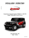
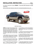
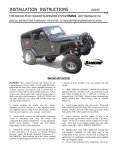
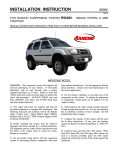
88517 Rev A Suspension System RS6517 Jeep Wrangler (JK) 88517 Rev A READ ALL INSTRUCTIONS THOROUGHLY FROM START TO FINISH BEFORE BEGINNING INSTALLATION IMPORTANT NOTES! WARNING: This suspension system will enhance the off-road performance of your vehicle. It will handle differently, both on and off-road, from a factory equipped passenger car or truck. Extreme care must be used to prevent loss of control or vehicle rollover during abrupt maneuvers. Failure to drive this vehicle safely may result in serious injury or death to the driver and passengers. ALWAYS WEAR your seat belts, REDUCE your speed, and AVOID sharp turns and other abrupt maneuvers. E. Install all nuts and bolts with a flat washer. When both SAE (small OD) and USS (large OD) washers are used in a fastener assembly, place the USS washer against the slotted hole and the SAE washer against the round hole. A. Before installing this system, have the vehicle's alignment and frame checked at a state approved facility. The alignment must be within factory specifications and the frame must be sound (no cracks, damage, or corrosion). G. Rancho parts come with a protective coating. Do not powdercoat, chrome, cadmium, or zinc plate any of the components in this system. If you wish to change the appearance of components enamel paint can be applied over the original coating. B. Do not install a body lift kit with Rancho’s suspension system or interchange parts from this system with components from another manufacturer. Use the following Rancho shock absorbers with this system: H. Do not weld anything to these components, and do not weld any of these components to the vehicle unless specifically stated in the instructions. If any component breaks or bends, contact your local Rancho dealer or Rancho for replacement parts. RS5000 / RS9000X Rear RS5332 RS99332 I. Some of the service procedures require the use of special tools designed for specific procedures. The following tools and supplies are recommended for proper installation of this kit. 5 Front RS5331 RS99331 F. Unless otherwise specified, tighten all bolts to the standard torque specifications listed at the end of the note's section. USE A TORQUE WRENCH for accurate measurements. C. Compare the contents of this system with the parts list in these instructions. If any parts are missing, including fasteners, contact the Rancho Technical Department at 1-734-384-7804. Each hardware kit in this system contains fasteners of high strength and specific size. Do not substitute a fastener of lesser strength or mix one hardware kit with another. D. Apply THREAD LOCKING COMPOUND to all bolts during installation. One drop on the exposed threads of each bolt before installing the nut is sufficient to provide an adequate bond. CAUTION: Thread locking compound may irritate sensitive skin. Read warning label on container before use. Jeep Service Manual Pitman Arm Puller C-4150-A Steering Linkage Puller C-3894-A Torque Wrench (250 FT-LB capacity) Hammer 1/2” Drive Ratchet and Sockets Combination Wrenches 3/8-16 Tap File Hydraulic Floor Jack Heavy Duty Jack stands Wheel Chocks (Wooden Blocks) Anti-seize compound Safety Glasses--Wear safety glasses at all times J. It is extremely important to replace torsion bars, CV flanges, and front drive shaft/pinion relationships as original. Be sure to mark left/right, front/rear, and indexing of mating parts before disassembly. A paint marker or light colored nail polish is handy for this. 2 K. Suspension components that use rubber or urethane bushings should be tightened with the vehicle at normal ride height. This will prevent premature failure of the bushing and maintain ride comfort. M. The required installation time for this system is approximately 4 hours. Check off the box ( 5 ) at the beginning of each step when you finish it. Then when you stop during the installation, it will be easier to find where you need to continue from. L. This suspension system was developed using a BF Goodrich® Mud-Terrain™ T/A® KM-35 x 12.50 x 18 D tire on a 18” x 9” wheel with 4.5” of backspacing. Total backspacing is 5.9”. Before installing any other combination, consult your local tire and wheel specialist. Actual tire size varies by manufacturer. N. Welding on a vehicle creates an electrical charge throughout the body and frame. Disconnect the vehicle’s battery prior to any welding. Place welding ground clamps as near as possible to the weld. Never use a vehicle suspension component as a welding ground point. O. Important information for the end user is contained in the consumer/installer information pack. If you are installing this system for someone else, place the information pack on the driver’s seat. Please include the installation instructions when you finish. P. Thank you for purchasing the best suspension system available. For the best installed system, follow these instructions. If you do not have the tools or are unsure of your abilities, have this system installed by a certified technician. RANCHO IS NOT RESPONSIBLE FOR DAMAGE OR FAILURE RESULTING FROM AN IMPROPER INSTALLATION. Compatible With OE Wheels No 2 Development Tire Size (actual) Optional Tire Size2 (actual) Wheel Size (backspacing) 35x12.5xR18 (34.8”x12.5”) 37x12.5xR18 (36.3”x12.8”) 18x9 (4.5”) Fitment of the optional tire size may require trimming to provide proper clearance. Bolt Size 5/16 3/8 7/16 1/2 9/16 5/8 3/4 STANDARD BOLT TORQUE SPECIFICATIONS INCH SYSTEM METRIC SYSTEM Grade 5 Grade 8 Bolt Size Class 9.8 Class 10.9 15 FT-LB 30 FT-LB 45 FT-LB 65 FT-LB 95 FT-LB 135 FT-LB 185 FT-LB 20 FT-LB 35 FT-LB 60 FT-LB 90 FT-LB 130 FT-LB 175 FT-LB 280 FT-LB M6 M8 M10 M12 M14 M16 M18 BOLT IDENTIFICATION 3 5 FT-LB 18 FT-LB 32 FT-LB 55 FT-LB 85 FT-LB 130 FT-LB 170 FT-LB 9 FT-LB 23 FT-LB 45 FT-LB 75 FT-LB 120 FT-LB 165FT-LB 240FT-LB Class 12.9 12 FT-LB 27 FT-LB 50 FT-LB 90 FT-LB 145 FT-LB 210 FT-LB 290 FT-LB PARTS LIST P/N 176439 176441 176443 176520 176522 176525 176572B 7789 860275 420080 420090 520080 520090 860613 860574 420067 860586 770154 770173 770195 DESCRIPTION Box 1 of 3 Left Front Brake Line Bracket Right Front Brake Line Bracket Front Bump Stop Spacer Lower Suspension Arm, Front Upper Suspension Arm, Front Composite Bearing Rod End Front Track Bar Bracket Pitman Arm Articulation Bushing Kit Sleeve 2.25” Crush Sleeve Bushing Bushing Shim Kit Washer Front Track Bar Hardware Kit Sleeve 3/8-16 x 1.5 HHTS M12-1.75 x 30 HHCS M12-1.75 Stover Nut M12 Washer M14-2.00 x 70 HHCS M14-2.00 Stover Nut M14 Washer M10-1.5 x 25 HHCS M10-1.5 Nylock Nut M10 Washer Thread Lock Bearing Kit High-misalignment Sleeve 7/8-14 Jam Nut High-misalignment Sleeve, Short M12-1.75 x 80 HHCS M12-1.75 Stover Nut M12 Washer QTY. 1 1 2 2 2 2 1 1 1 4 2 8 4 1 12 1 1 2 1 1 2 1 1 2 1 1 2 2 1 8 4 4 1 1 2 P/N DESCRIPTION 860625 602627 770196 94180 780281 88517 94119 94177 Rod End Kit 7/8-14 Male Rod End .75-M12 High-misalignment Sleeve Information Pack Rancho Decal Instructions Consumer/Warranty Information Warning Sticker Box 2 of 3 Rear Track Bar Bracket Rear Brake Line Bracket Rear Bump Stop Spacer Rear Sway Bar Bracket Lower Suspension Arm, Rear Upper Suspension Arm, Rear Rear Hardware Kit Sleeve M14-2.00 x 80 HHCS M14-2.00 Stover Nut M14 Washer M12-1.75 x 30 HHCS M12-1.75 Stover Nut M12 Washer M10-1.50 x 50 HHCS M10 Washer M8-1.25 x 20 HHCS M8-1.25 Nylock Nut M8 Washer 1/4-20 x .75 HHCS 1/4-20 x Stover Nut 1/4 SAE Washer Box 3 of 3 Front Coil Spring Rear Coil Spring 176440B 176442 176444 176445 176523 176524 860575 420067 694 817 4 QTY. 1 2 4 1 1 1 1 1 1 2 2 2 2 2 1 1 1 1 2 1 1 2 4 4 4 4 8 4 4 8 2 2 Front Suspension 6) Remove the nut from the drag link at the pitman arm. Separate the drag link ball stud from the pitman arm with a puller tool. Do not use a pickle fork. FRONT SUSPENSION SHOCK ABSORBER & COIL SPRING REMOVAL 7) Support the front axle with a jack. Remove the shock absorber upper nut, retainer, and bushing. 1) Park vehicle on a level surface. Set the parking brake and chock rear wheels. Disconnect the negative ground cable from the battery. 8) Remove the shock absorber lower nut and bolt. Remove the front shock absorber. 2) Remove the end link to frame bracket nut and bolt. Remove the ball stud nut at the sway bar. Remove the end link. Repeat for other side. 3) 9) Repeat steps 6 and 7 for the other side. DO NOT REUSE ORIGINAL SHOCK ABSORBERS. Remove the track bar to frame bracket nut and bolt. 10) If necessary, disconnect any vent hoses and electrical wiring from the axle. Separate the brake hoses from the frame rails by removing the bracket bolts. 4) Raise the front of the vehicle and support the frame with jack stands. Remove the front wheels and set them aside. 5) 11) Carefully lower the front axle and remove the coil springs. Push down on axle if necessary. If equipped, remove the transmission skid plate. CAUTION: Do not allow the front axle to hang by any hoses or cables. 5 6) Thread jam nut on rod end 602627 until 6 threads are left. Apply anti-seize compound and thread rod end into upper suspension arm 176522. SUSPENSION ARM REPLACEMENT 1) Support the front axle with a jack. 7) Insert the sleeves from kit 860625 and attach rod end to frame bracket with the original hardware. Attach bracket end of upper suspension arm 176522 to the axle bracket with the original hardware. See illustration 3. 2) Remove the driver side upper suspension arm from the frame and axle brackets. Remove the driver side lower suspension arm from the frame and axle brackets. See Illustration 1. Illus. 1 Illus. 3 3) Lubricate two bushings (520080) and a longer sleeve from kit 860275 with synthetic lithium grease. Insert bushings and sleeve into the front barrel of lower suspension arm 176520. See illustration 2. 8) Center rod end 602627 and tighten jam nut to 125 ft. lbs. Do not tighten upper suspension arm bolts until vehicle is at normal ride height. 9) Repeat steps 2 through 8 to install suspension arms on the passenger side. NOTE: To disconnect the upper suspension arm from the passenger side frame bracket, the mounting bolt must be cutoff or the exhaust removed. Additional 12mm hardware is supplied in kit 860586 for the cutoff procedure. Illus. 2 4) Apply a film of grease to the outside of the installed bushings. Place a washer from kit 860587 against each bushing. Attach the front barrel assembly to the driver side axle bracket with the original hardware. See illustration 3. 5) Insert the longer high-misalignment sleeves from kit 860586 into the rear barrel of lower suspension arm 176520. Attach the rear barrel assembly to the frame bracket with the original hardware. Tighten nuts and bolts to 125 ft. lbs. Illus. 4 6 PITMAN ARM & TRACK BAR BRACKET INSTALLATION BUMP STOP SPACER, COIL SPRING & SHOCK ABSORBER INSTALLATION 1) Center the steering wheel and mark the position of the original pitman arm. Remove the nut and washer from the steering gear shaft. 1) Drill a 5/16" hole through the center of the coil spring axle pad. For ease of installation, tap the hole (3/816). 2) Remove the pitman arm from the steering gear with pitman arm puller C-4150-A. 2) Install original insulator on top of coil spring 694B. Place bump stop spacer 176443 inside the coil spring. 3) Insert track bar bracket 176572B into the original track bar frame bracket. See illustration 6. NOTE: If you have a winch mounted to the front bumper, add spring spacer RS70082 (purchased separately) to compensate for the additional weight. 3) Insert the spring assembly into the upper pocket and onto the axle pad. See illustration 5. Align pig tail with groove in axle pad. 4) Attach the bump stop spacer to the axle pad with the self-tapping screw from kit 860574. 5) Repeat steps 2 through 4 for the other side. 6) Install retaining washer and bushing on NEW shock absorber, insert shock into upper mounting hole. Install bushing, washer and nut. Tighten nut until bushings compress. Repeat for other side. Illus. 6 4) Using an existing hole, loosely attach the inside edge of bracket 176572B with the 12mm hardware from kit 860574. 5) Using an existing hole, loosely attach the outside edge of bracket 176572B with the 10mm hardware from kit 860574. 6) Insert sleeve 420067 into the bracket at the original track bar location. Install the original hardware. Tighten OE bolt to 125 ft. lbs. Tighten the 12mm bolt to 75 ft. lbs. and the 10mm bolt to 45 ft. lbs. NOTE: Welding track bar bracket 176572B to the frame bracket is recommended for extreme off-road use. Refer to “Important Note N” on page 3. Welding should be performed by a trained professional. Clean area of all paint/coating. Repaint cleaned area after welding. Illus. 5 7) Raise front axle and attach shock lower mounts to axle brackets with the original hardware. Tighten nuts and bolts to 56 ft. lbs. 7) Attach track bar to bracket 176572B with the 14mm hardware from kit 860574. Insert bolt from rear and do not tighten until vehicle is at normal ride height. 8) Reattach vent hose and electrical wiring if necessary. 8) Align and install new pitman arm 7789 on the steering gear shaft. Install the washer and nut. Tighten the nut to 185 ft. lbs. 7 9) Install the drag link ball stud to the pitman arm. Install the nut and tighten to 60 ft. lbs. 10) To reposition the front wheels, turn the drag link adjustment sleeve six to eight turns in (shorten). Adjustment sleeve bolts must face forward. See illustration 7. Illus. 8 BRAKE HOSE BRACKET INSTALLATION 1) Attach left brake line bracket 176439 to the brake hose with the 1/4” hardware from kit 860575. Attach bracket to frame with the original bolt. See illustration 9. Tighten nuts and bolts securely. Carefully bend brake line tube away from frame rail. Illus. 7 SWAY BAR END LINK INSTALLATION NOTE: Requires quick disconnect kit RS6756B or solid end link kit RS6753B for a complete installation. 1) Apply silicone lubricant and press the supplied bushings into the upper and lower end links (176461B and 176462B) or end link (176088B). 2) Apply silicone lubricant and press a supplied sleeve into each bushing. 3) For RS6756B, install a rubber washer from kit 860580 on the lower end link. Connect upper and lower end links with the lynch pin from kit 860580. Illus. 9 4) Attach end link assembly to sway bar and axle bracket with the supplied hardware. See illustration 8. Tighten nuts and bolts to 70 ft. lbs. 5) 2) Repeat step 1 to install right brake line bracket 176441 on the passenger side. Repeat steps 1 through 4 for the other side. 3) Slide grommets on ABS wire to provide slack for full suspension/turning movement. Reattach ABS wires to brake lines. 4) Install front wheels and lower vehicle to the ground. Tighten lug nuts to 80--110 ft. lbs. 8 5) Tighten the Track bar nut and bolt to 120 ft. lbs. 6) Tighten the upper suspension arm bolts to 75 ft. lbs. Rear Suspension 6) Carefully lower the rear axle until the coil springs are free from the upper mount seat. Remove the coil springs. REAR SUSPENSION SHOCK ABSORBER & COIL SPRING REMOVAL CAUTION: Do not allow the axle to hang by any hoses or cables. 1) Chock front wheels. Disconnect the track bar from the frame bracket. Disconnect the sway bar end links from the axle brackets. SUSPENSION ARM REPLACEMENT 2) Raise the rear of the vehicle and support the frame with jack stands. Remove the rear wheels. 1) Remove the driver side lower suspension arm nut and bolt from the axle bracket. 3) Remove bolts and separate the brake hoses from the frame rails. If necessary, disconnect any vent hoses and electrical wiring from the axle. 2) Remove the flagnut at the frame rail bracket. Remove the lower suspension arm. 4) Remove the bolts from the brake cable hanger above the rear axle. Remove the hanger from the cables. 3) Remove the driver side upper suspension arm flagnut and bolt from the axle bracket. 5) Support the rear axle with a floor jack. Remove the shock absorber upper mounting bolts. Remove the lower nut and bolt from the axle bracket. Remove the shock absorbers. 4) Remove the flagnut and bolt at the frame rail bracket. Remove the upper suspension arm. 9 13) Repeat steps 1 through 12 for the passenger side. 5) Lubricate two bushings (520080) and a longer sleeve (420080) from kit 860275 with synthetic lithium grease. Insert bushings and sleeve into lower suspension arm 176523. Refer back to illustration 2. 6) Insert two of the longer high-misalignment sleeves from kit 860586 into the composite bearing of suspension arm 176523. 7) Attach the bearing end of suspension arm 176523 to the frame bracket with the original hardware. Insert two greased washers from kit 860613 and attach the bushing end to the axle bracket with the original hardware. See illustration 10. Illus. 11 COIL SPRING & SHOCK ABSORBER INSTALLATION 1) Place the new coil springs (817) onto the axle pads. Align upper pigtails towards the front of the vehicle. Raise the axle until the coil springs seat on the upper isolators. See illustration 12. Illus. 10 8) Install jam nut on rod end 176525 until 5-6 threads (2dr) or 2-3 threads (4dr) are left. Apply anti-seize compound and thread rod end into upper suspension arm 176524. 9) Lubricate two bushings (520090) and a shorter sleeve (420090) from kit 860275 with synthetic lithium grease. Insert bushings and sleeve into upper suspension arm 176524. Refer back to illustration 5. 10) Insert two of the shorter high-misalignment sleeves from kit 860586 into the composite bearing of rod end 176525. 11) Attach the bearing end of the suspension arm assembly to the frame bracket with the original hardware. Insert two greased washers from kit 860613 and attach the bushing end to the axle bracket with the original hardware. See illustration 11. Illus. 12 NOTE: When installing coil springs, make sure that the rubber isolator is positioned in the upper mount and the small egg-shaped coil end is at the bottom. 12) Center rod end 176525 and tighten jam nut. Do not tighten suspension arm bolts until vehicle is at normal ride height. 10 2) Attach new Rancho rear shocks to the upper mounting brackets with the original bolts. Tighten bolts to 37 ft. lbs. 3) Loosely attach shocks to the axle brackets with the original hardware. TRACK BAR BRACKET INSTALLATION 1) Loosely attach track bar bracket 176440B to the track bar with the original hardware. Insert bolt from front to rear. See illustration 13. Illus. 14 3) Attach sway bar to frame rail with the 10mm hardware from kit 860575. Tighten bolts to 35 ft lbs. 4) Attach brake line bracket 176442 to the frame rail with the original brake line bolt. See illustration 14. 5) Attach brake line to the inside of bracket 176442 with the 1/4” hardware from kit 860575. Tighten nuts and bolts to 12 ft lbs. 6) To provide clearance for the end link, grind the axle bracket at the locations shown in illustration 15. Illus. 13 7) Temporarily disconnect lower shock mount. Drill a 12mm hole 1” above and 1/4” toward the rear of the original end link mounting hole. See illustration 15. Reinstall shock. 2) Place track bar bracket 176440B over the original frame bracket. The front edge of the new bracket should fit inside the original bracket. 3) Insert the sleeve from kit 860575 and attach track bar bracket 176440B to the frame bracket with the 14mm hardware from kit 860575. See illustration 13. 4) Using an existing hole, attach the top of bracket 176440B to the frame bracket with the 12mm hardware from kit 860575. Tighten the 12mm and OE bracket hardware to specifications. NOTE: Do not tighten the original track bar bolt until the vehicle is at normal ride height. SWAY BAR & BRAKE LINE BRACKET INSTALLATION 1) Illus. 15 Disconnect the sway bar from the frame rail. 8) Using the new hole, attach end link to axle bracket with the original hardware. Tighten nut and bolt to 40 ft lbs. 2) Insert sway bar bracket 176445 between the sway bar and the frame rail. See illustration 14. 9) 11 Repeat steps 1 through 8 for the other side. BUMP STOP BRACKET INSTALLATION FINAL CHECKS & ADJUSTMENTS 1) Using the original holes on the axle pad, attach bump stop bracket 176444 to the axle with the 8mm hardware from kit 860575. See illustration 16. 1) Turn the front wheels completely left then right. Verify adequate tire, wheel, brake hose and ABS wire clearance. Inspect steering and suspension for tightness and proper operation. 2) With the suspension at maximum extension (full droop), inspect and rotate all axles and drive shafts. Check for binding and proper slip yoke insertion. The slip yoke should be inserted a minimum of one inch into the transfer case and/or transmission. 3) Ensure that the vehicle brake system operates correctly. If new brake hoses were installed, verify that each hose allows for full suspension movement. 4) Readjust headlamps. manufacturer’s specifications. Illus. 16 2) Repeat for other side. Adjustment 4) Tighten the track bar bolts to 120 ft. lbs. Tighten the shock absorber lower mounting bolts to 56 ft. lbs. Tighten the suspension arm bolts to 125 ft. lbs. 5) Alignment Specifications Preferred Caster Camber (fixed angle) Toe-In (each wheel) Thrust Angle 3) Install rear wheels and lower vehicle to the ground. Tighten lug nuts to 80-110 FT-LBS. Have vehicle Aligned to 5.0° -0.25° 0.15° 0 Range ±1.0° ±0.63° ±0.15° ±0.15° NOTE: The length of the upper suspension arms may be adjusted to fit an aftermarket driveshaft. Consult a driveline specialist. Reconnect the battery ground cable. Please retain this publication for future reference. See Important Note O. 12