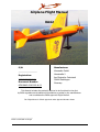
1
Airplane Flight Manual
XA42
S/N:
Manufacturer:
_________________
XtremeAir GmbH
Harzstraße 2
Registration:
Am Flughafen Cochstedt
___________________
39444 Hecklingen
Document Number:
Germany
AFM-XA42-0040-002-A.01
This Manual includes the material required to be furnished to the pilot
by EASA regulations and additional informations provided by the manufacturer
and constitutes the EASA approved Flight Manual.
This Flight Manual is EASA approved under Approval Number A.507
_______________________
EASA certification manager
Cover
Airplane Flight Manual XA42
AFM-XA42-0040-002-A.01
Intentionally left blank
Page
I
Page date:
24.01.2011
Airplane Flight Manual XA42
AFM-XA42-0040-002-A.01
LOG OF REVISIONS
Issue
Date
A.01
27.01.2011
Page date:
24.01.2011
Approved
Page
II
Airplane Flight Manual XA42
AFM-XA42-0040-002-A.01
LOG OF EFFECTIVE PAGES
Issue
Cover and l
A.01
II and III
A.01
lV and V
A.01
VI and VII
A.01
Vlll and Chapter 01, Page 1
A.01
Chapter 01, Page 2 and Chapter 01, Page 3
A.01
Chapter 01, Page 4 and Chapter 01, Page 5
A.01
Chapter 01, Page 6 and Chapter 01, Page 7
A.01
Chapter 01, Page 8 and Chapter 02, Page 1
A.01
Chapter 02, Page 2 and Chapter 02, Page 3
A.01
Chapter 02, Page 4 and Chapter 02, Page 5
A.01
Chapter 02, Page 6 and Chapter 02, Page 7
A.01
Chapter 02, Page 8 and Chapter 02, Page 9
A.01
Chapter 02, Page 10 and Chapter 02, Page 11
A.01
Chapter 02, Page 12 and Chapter 03, Page 1
A.01
Chapter 03, Page 2 and Chapter 03, Page 3
A.01
Chapter 03, Page 4 and Chapter 03, Page 5
A.01
Chapter 03, Page 6 and Chapter 03, Page 7
A.01
Chapter 03, Page 8 and Chapter 04, Page 1
A.01
Chapter 04, Page 2 and Chapter 04, Page 3
A.01
Chapter 04, Page 4 and Chapter 04, Page 5
A.01
Chapter 04, Page 6 and Chapter 04, Page 7
A.01
Chapter 04, Page 8 and Chapter 04, Page 9
A.01
Chapter 04, Page 10 and Chapter 04, Page 11
A.01
Chapter 04, Page 12 and Chapter 05, Page 1
A.01
Chapter 05, Page 2 and Chapter 05, Page 3
A.01
Chapter 05, Page 4 and Chapter 05, Page 5
A.01
Chapter 05, Page 6 and Chapter 05, Page 7
A.01
Chapter 05, Page 8 and Chapter 05, Page 9
A.01
Chapter 06, Page 1 and Chapter 05, Page 2
A.01
Chapter 06, Page 3 and Chapter 06, Page 4
A.01
Chapter 06, Page 5 and Chapter 06, Page 6
A.01
Chapter 06, Page 7 and Chapter 07, Page 1
A.01
Chapter 07, Page 2 and Chapter 07, Page 3
A.01
Chapter 07, Page 4 and Chapter 07, Page 5
A.01
Chapter 07, Page 6 and Chapter 07, Page 7
A.01
Chapter 07, Page 8 and Chapter 07, Page 9
A.01
Chapter 07, Page 10 and Chapter 07, Page 11
A.01
Chapter 08, Page 1 and Chapter 08, Page 2
A.01
Chapter 08, Page 3
A.01
Page date:
24.01.2011
Page
III
Airplane Flight Manual XA42
AFM-XA42-0040-002-A.01
TABLE OF CONTENTS
LOG OF REVISIONS ........................................................................................................... II
LOG OF EFFECTIVE PAGES................................................................................................ III
TABEL OF CONTENTS ......................................................................................................... IV
INTRODUCTION ................................................................................................................ VI
NOTES ................................................................................................................................ VI
WARNINGS; CAUTIONS AND NOTES ............................................................................... VII
1
1.1
1.2
1.3
1.4
1.5
1.6
1.7
1.8
1.9
1.10
1.11
1.12
1.13
2
2.1
2.2
2.3
2.4
2.5
2.6
2.7
2.8
2.9
2.10
2.11
2.12
2.13
2.14
2.15
2.16
2.17
3
3.1
3.2
3.3
3.4
3.5
3.6
3.7
3.8
3.9
3.10
3.11
4
4.1
4.2
Page
GENERAL .......................................................................................................... 1-01
DESCRIPTION .......................................................................................................... 1-01
SPECIICATION OF CATEGORY .................................................................................. 1-01
MANUFACTURER ...................................................................................................... 1-01
TECHNICAL DATA .................................................................................................... 2-01
ENGINE ................................................................................................................... 4-01
PROPELLER ............................................................................................................. 4-01
EXHAUST SYSTEM.................................................................................................... 4-01
FUEL ....................................................................................................................... 4-01
OIL ......................................................................................................................... 5-01
SMOKE OIL .............................................................................................................. 5-01
LOADING ................................................................................................................. 5-01
TERMINOLOGY ........................................................................................................ 5-01
CONVERSION TABLE ................................................................................................ 7-01
LIMITATIONS................................................................................................... 1-02
GENERAL ................................................................................................................. 1-02
AIRSPEED (IAS) ....................................................................................................... 1-02
CROSSWIND COMPONENT ....................................................................................... 1-02
ENGINE ................................................................................................................... 2-02
PROPELLER ............................................................................................................. 3-02
WEIGHT LIMITS....................................................................................................... 3-02
WEIGHT AND CENTER OF GRAVITY ENVELOPE ......................................................... 3-02
BAGGAGE ................................................................................................................ 3-02
ACROBATIC MANEUVERS ......................................................................................... 4-02
LOAD FACTORS ....................................................................................................... 5-02
FLIGHT CREW LIMITS .............................................................................................. 6-02
KINDS OF OPERATIONAL LIMITS .............................................................................. 6-02
MAXIMUM OPERATING ALTITUDE ............................................................................. 6-02
TYRE PRESSURE ...................................................................................................... 6-02
SMOKE OIL .............................................................................................................. 6-02
MARKINGS AND PLACARDS ...................................................................................... 6-02
KINDS OF OPERATION EQUIPMENT LIST .................................................................10-02
EMERGENCY PROCEDURES.............................................................................. 1-03
INTRODUCTION ....................................................................................................... 1-03
AIR SPEEDS FOR EMERGENCY OPERATION ............................................................... 2-03
OPERATIONAL CHECKLIST ....................................................................................... 2-03
FORCED LANDINGS .................................................................................................. 4-03
FIRES ...................................................................................................................... 5-03
ICING – INADVERTENT ENCOUNTER ........................................................................ 5-03
UNITENTIONAL SPIN ............................................................................................... 6-03
BAIL-OUT ................................................................................................................ 6-03
EMERGENCY EXIT AFTER FLIP-OVER ........................................................................ 6-03
ELEVATOR CONTROL FAILURE ................................................................................. 6-03
LIGHTNING STRIKE ................................................................................................. 7-03
NORMAL PROCEDURES .................................................................................... 1-04
GENERAL ................................................................................................................. 1-04
PREFLIGHT INSPECTION .......................................................................................... 1-04
IV
Page date:
24.01.2011
Airplane Flight Manual XA42
AFM-XA42-0040-002-A.01
4.3
4.4
4.5
4.6
4.7
4.8
4.9
4.10
4.11
4.12
5
5.1
5.2
5.3
5.4
5.5
5.6
5.7
5.8
6
6.1
6.2
6.3
6.4
6.5
6.6
7
7.1
7.2
7.3
7.4
7.5
7.6
7.7
7.8
7.9
7.10
7.11
7.12
7.13
7.14
7.15
7.16
8
8.1
8.2
8.3
8.4
8.5
8.6
8.7
CHECKLIST PROCEDURES ........................................................................................ 2-04
STARTING PROCEDURES .......................................................................................... 5-04
TAXIING THE AIRCRAFT ........................................................................................... 5-04
TAKE-OFF PROCEDURES .......................................................................................... 6-04
CLIMB ..................................................................................................................... 7-04
CRUISE ................................................................................................................... 7-04
LANDING PROCEDURES ........................................................................................... 7-04
SHUTDOWN ............................................................................................................. 8-04
AFTER LEAVING THE AIRCRAFT................................................................................ 9-04
ACROBATIC MANEUVERS ......................................................................................... 9-04
PERFORMANCE ................................................................................................ 1-05
GENERAL ................................................................................................................. 1-05
ISA CONVERSION .................................................................................................... 2-05
AIRSPEED CALIBRATION .......................................................................................... 3-05
STALL SPEED ........................................................................................................... 3-05
TAKE-OFF PERFORMANCE ........................................................................................ 4-05
RATE OF CLIMB PERFORMANCE................................................................................ 6-05
CRUISE PERFORMANCE, RANGE, ENDURANCE AND FUEL CONSUMTION..................... 6-05
LANDING PERFORMANCE ......................................................................................... 7-05
WEIGHT & BALANCE ........................................................................................ 1-06
GENERAL ................................................................................................................. 1-06
AIRCRAFT WEIGHING PROCEDURE ........................................................................... 1-06
CENTER OF GRAVITY CALCULATION (SAMPLE) ......................................................... 2-06
LOADING WEIGHTS AND MOMENTS ......................................................................... 3-06
WEIGHTS AND MOMENTS LIMITS ............................................................................. 4-06
EUIPMENT LIST XA42 S/N:101.................................................................................. 5-06
DESCRIPTION AND OPERATION OF AIRCRAFT AND SYSTEMS ....................... 1-07
AIRCRAFT ................................................................................................................ 1-07
FUSELAGE ............................................................................................................... 1-07
WING ...................................................................................................................... 1-07
EMPENNAGE ............................................................................................................ 2-07
FLIGHT CONTROL SYSTEM ....................................................................................... 2-07
INSTRUMENTATION ................................................................................................. 3-07
LANDING GEAR ........................................................................................................ 5-07
SEAT AND SEATBELTS ............................................................................................. 5-07
CANOPY .................................................................................................................. 6-07
POWER PLANT ......................................................................................................... 6-07
FUEL SYSTEM .......................................................................................................... 8-07
ELECTRICAL SYSTEM ............................................................................................... 9-07
CABIN ENVIRONMENT CONTROL .............................................................................. 9-07
BAGGAGE COMPARTMENT .......................................................................................10-07
PITOT - STATIC SYSTEM .........................................................................................10-07
SMOKE SYSTEM ......................................................................................................10-07
HANDLING, SERVICING AND MAINTENANCE ................................................. 1-08
INTRODUCTION ....................................................................................................... 1-08
AIRPLANE INSPECTION PERIODS ............................................................................. 1-08
PILOT CONDUCTED PREVENTIVE MAINTENANCE ...................................................... 1-08
ALTERATIONS OR REPAIR ........................................................................................ 1-08
SERVICING .............................................................................................................. 1-08
GOUND HANDLING .................................................................................................. 2-08
CLEANING AND PROTECTION ................................................................................... 2-08
Page date:
24.01.2011
Page
V
Airplane Flight Manual XA42
AFM-XA42-0040-002-A.01
INTRODUCTION
This Airplane Flight Manual contains 9 chapters, and includes the material required to be known by
the pilot according to EASA CS-23.
It also contains supplementary data supplied by XtremeAir GmbH.
NOTES
This Airplane Flight Manual applies only to the aircraft whose nationality and registration marks are
noted on the title page.
This Airplane Flight Manual is only valid in connection with the latest approved revision.
It is the responsibility of the pilot to be familiar with the contents of this Airplane Flight Manual
including revisions and any relevant supplements.
Pages of this Airplane Flight Manual must not be exchanged and no alterations of or additions to the
approved contents may be made without the XtremeAir GmbH/EASA approval.
The editor has the copyright of this Airplane Flight Manual and is responsible for edition of
revisions/amendments and supplements.
Amendments, which affect the airworthiness of the aircraft will be announced in the mandatory
Service Bulletins issued by the manufacturer XtremeAir GmbH coming along with the "Airworthiness
Directive" (AD) publication issued by the EASA. The owner is responsible for incorporating prescribed
amendments and should make notes about these on the records of amendments
Should this Airplane Flight Manual get lost, please inform
XtremeAir GmbH,
Harzstraße 2, Am Flughafen Cochstedt,
39444 Hecklingen, Germany.
Should this Airplane Flight Manual be found, kindly forward it to the civil aviation authority in the
country the aircraft is registered.
Page date:
24.01.2011
Page
VI
Airplane Flight Manual XA42
AFM-XA42-0040-002-A.01
WARNINGS, CAUTIONS AND NOTES
The following definitions apply to Warnings, Cautions, and Notes:
WARNING
Operating procedures, techniques, etc., which could result in personal injury or loss of life
if not carefully followed.
CAUTION
Operating procedures, techniques, etc., which could result in damage to equipment
if not carefully followed.
NOTE
Operating procedures, techniques, etc., which are considered essential to emphasize.
Page
VII
Page date:
24.01.2011
Airplane Flight Manual XA42
AFM-XA42-0040-002-A.01
Intentionally left blank
Page date:
24.01.2011
Page
VIII
Airplane Flight Manual XA42
AFM-XA42-0040-002-A.01
1.
GENERAL
1.1
DESCRIPTION
The XA42 is a two-seat, high performance acrobatic tailwheel airplane.
The structure is manufactured from carbon/honeycomb sandwich.
1.2
SPECIFICATION OF CATEGORY
The aircraft is certified in the Utility and Acrobatic category according to EASA CS-23.
EASA type certificate data sheet A.507
1.3
MANUFACTURER
XtremeAir GmbH
Harzstraße 2, Am Flughafen Cochstedt
39444 Hecklingen
Germany
Page
1
Chapter 01
Page date:
09.11.2010
Airplane Flight Manual XA42
AFM-XA42-0040-002-A.01
1.4
TECHNICAL DATA
1.4.1
3 VIEW DRAWING
All dimensions in millimeters
Page date:
24.01.2011
Page
2
Chapter 01
Airplane Flight Manual XA42
AFM-XA42-0040-002-A.01
1.4.2
MAIN DATA
Length overall
6670 mm
Height overall (ground attitude)
2542 mm
Span
7500 mm
Wheel base
4425 mm
Wheel track
2000 mm
1.4.3
WING
Wing plan form
Trapezoid
Wing span
7500 mm
Wing area
11.25 m²
Aspect ratio
5.00
Airfoil
PS-1-16 / Tip PS-1-09
Root chord
2060 mm
Tip chord
950 mm
MAC
1505 mm
Aileron span
3220 mm
Aileron area
1.26 m²
Aileron deflection
± 30 °
1.4.4
HORIZONTAL TAIL (INCLUDING ELEVATOR)
Plan form
Trapezoid
Span
2600 mm
Area
2.97 m²
Airfoil
DU86-MOD1
1.4.5
ELEVATOR
Span
3200 mm
Area
1.45 m²
Deflection
± 27 °
1.4.6
FLETTNER TAB
Span:
400 mm
Tip chord:
130 mm
Deflection:
± 30 °
Page
3
Chapter 01
Page date:
24.01.2011
Airplane Flight Manual XA42
AFM-XA42-0040-002-A.01
1.4.7
VERTICAL TAIL (INCLUDING RUDDER)
Plan form:
Trapezoid
Height:
1100 mm
Area:
1.54 m²
Airfoil:
DU86-MOD1
1.4.8
RUDDER
Height:
1400 mm
Area:
0.82 m²
Deflection:
± 30 °
1.5
ENGINE
Manufacturer:
Lycoming Engines, Williamsport, PA 17701, USA
Type:
AEIO-580-B1A
Rated power:
Acrobatic:
235 kW / 315 hp @ 2700 rpm
Rated power:
Utility:
233 kW / 312 hp @ 2670 rpm
1.6
PROPELLER
Manufacturer:
MT-Propeller Entwicklung GmbH, 94348 Atting, Germany
Type:
MTV-9-B-C/C203-20d
1.7
EXHAUST SYSTEM
Manufacturer:
Gomolzig GmbH, Eisenwerkstraße 9, 58332 Schwelm, Germany
Type:
3 in 1 each side
1.8
FUEL
Fuel type:
Aviation Gasoline (Avgas) 100LL
For alternative fuel grades see latest issue of Textron
Lycoming S.I. No. 1070
Minimum / Maximum 100/130 octane
Total fuel capacity:
275 l / 72.5 US gal
• Wing tanks:
2 x 10⁵ l / 2 x 27.7 US gal
• Acro tank:
65 l / 17.1 US gal
Usable fuel capacity (Total):
273 l / 72.0 US gal
Usable fuel capacity (Acro):
64 l / 16.9 US gal
Page
4
Chapter 01
Page date:
24.01.2011
Airplane Flight Manual XA42
AFM-XA42-0040-002-A.01
1.9
OIL
Maximum sump capacity:
15.15 l / 16 US qt
Minimum sump capacity:
8.52 l / 9 US qt
Average Ambient Air Temp.
Mil-L6082 grades
Mil-22851 ashless dispersant grades
All temperatures
---
SAE 15W50 or 20W50
> 27°C (80°F)
SAE 60
SAE 60
> 16°C (60°F)
SAE 50
SAE 40 or SAE 60
-1°C to 32°C (30°F to 90°F)
SAE 40
SAE 40
-18°C to 21°C (0°F to 70°F
SAE 30
SAE 30, SE 40 or 20W50
-18°C to 32°C (0°F to 90°F)
SAE 20W50
SAE 20W50 or SAE 15W50
< -12°C (10°F)
SAE 20
SAE 30 or 20W30
Single or multi-viscosity aviation grade oils see latest issue of Textron Lycoming S.I. No. 1014
1.10
SMOKE OIL
Smoke Oil type:
Straight paraffin oil,
viscosity 30-50 cts at 20°C (68°F),
initial boiling point > 330°C (626°F)
For example: Fauth FC05, Texaco Canopus 13 or equivalent.
Total Smoke Oil capacity:
1.11
LOADING
-2
Wing Loading kg / m
Power – Weight Ratio kg / hp-1
1.12
28 l / 7.4 US gal
Utility Category
Acrobatic Category
84.4
3.01
75.5
2.69
TERMINOLOGY
Air Speeds
CAS
IAS
KIAS
TAS
VA
VNE
VNO
VS
VX
VY
Calibrated air speed (CAS = TAS in standard atmospheric conditions at sea level)
Indicated air speed
Indicated air speed in knots
True air speed (same as CAS compensated for altitude, temperature and density)
Maneuvering speed
Never exceed speed
Maximum structural cruising speed
Stalling speed / minimum steady flight speed
Best angle-of-climb speed
Best rate-of-climb speed
Meteorological Terminology
ISA
OAT
Page date:
24.01.2011
International standard atmospheric condition
Outside air temperature
Page
Chapter
5
01
Airplane Flight Manual XA42
AFM-XA42-0040-002-A.01
Secondary Terminology
fpm
ft
in
m
l
US gal
US quartt
hp
h
kts
km/h
lbs
MP
NM
rpm
CG
Arm
Moment
SL
Page date:
24.01.2011
Feet per minute
Feet (1 ft = 304.8 mm)
Inch (1 in = 25.4 mm)
Meter
Liter
US (liquid) gallon (1 US gal = 3.79 Liter)
US (liquid) quart (1 US qt = 0.946 Liter)
Horse power (English)
Hour
Knots (nautical miles per hour)
Kilometer per hour
English pound (1 lbs = 0.4536 kg)
Manifold pressure
Nautical mile (1 nm = 1.852 km)
Revolutions per minute
Center of gravity
Is the horizontal distance from reference datum
Is the product of the weight of an item multiplied by its arm
Sea level
Page
6
Chapter 01
Airplane Flight Manual XA42
AFM-XA42-0040-002-A.01
1.13
kts
50
55
60
65
70
75
80
85
90
95
100
105
110
115
120
125
130
135
140
145
150
155
160
165
170
175
180
185
190
195
200
205
210
215
220
225
230
235
CONERVERSION TABLE
km/h
93
102
111
120
130
139
148
157
167
176
185
194
204
213
222
232
241
250
259
269
278
287
296
306
315
324
333
343
352
361
370
380
389
398
407
417
426
435
Page
7
Chapter 01
km/h
90
100
110
120
130
140
150
160
170
180
190
200
210
220
230
240
250
260
270
280
290
300
310
320
330
340
350
360
370
380
390
400
410
420
430
440
450
460
kts
49
54
59
65
70
76
81
86
92
97
103
108
113
119
124
130
135
140
146
151
157
162
167
173
178
184
189
194
200
205
211
216
221
227
232
238
243
248
ft
500
1000
1500
2000
2500
3000
3500
4000
4500
5000
5500
6000
6500
7000
7500
8000
8500
9000
9500
10000
10500
11000
11500
12000
12500
13000
13500
14000
14500
15000
15500
16000
16500
17000
17500
18000
18500
19000
m
152
305
457
610
762
914
1067
1219
1372
1524
1676
1829
1981
2134
2286
2438
2591
2743
2896
3048
3200
3353
3505
3658
3810
3962
4115
4267
4420
4572
4724
4877
5029
5182
5334
5486
5639
5791
m
250
375
500
625
750
875
1000
1125
1250
1375
1500
1625
1750
1875
2000
2125
2250
2375
2500
2625
2750
2875
3000
3125
3250
3375
3500
3625
3750
3875
4000
4125
4250
4375
4500
4625
4750
4875
ft
820
1230
1640
2051
2461
2871
3281
3691
4101
4511
4921
5331
5741
6152
6562
6972
7382
7792
8202
8612
9022
9432
9843
10253
10663
11073
11483
11893
12303
12713
13123
13533
13944
14354
14764
15174
15584
15994
nm
10
20
30
40
50
60
70
80
90
100
110
120
130
140
150
160
170
180
190
200
220
240
260
280
300
320
340
360
380
400
420
440
460
480
500
520
540
560
km
19
37
56
74
93
111
130
148
167
185
204
222
241
259
278
296
315
333
352
370
407
444
482
519
556
593
630
667
704
741
778
815
852
889
926
963
1000
1037
km
10
20
30
40
50
60
70
80
90
100
110
120
130
140
150
160
170
180
190
200
250
300
350
400
450
500
550
600
650
700
750
800
850
900
950
1000
1050
1100
nm
5
11
16
22
27
32
38
43
49
54
59
65
70
76
81
86
92
97
103
108
135
162
189
216
243
270
297
324
351
378
405
432
459
486
513
540
567
594
Page date:
24.01.2011
Airplane Flight Manual XA42
AFM-XA42-0040-002-A.01
Intentionally left blank
Page date:
24.01.2011
Page
8
Chapter 01
Airplane Flight Manual XA42
AFM-XA42-0040-002-A.01
2.
LIMITATIONS
2.1
GENERAL
This chapter includes limitations for operation of the aircraft, the engine, the standard systems and
the standard equipment. Also it gives information on the instrument markings and basic placards. The
limitations in this chapter have been approved by the EASA. Observance of these operating limitations
is required by national aviation regulations.
NOTE
In case of an XA42 is equipped with specific options additional information required for safe operation
will be contained in chapter 9.
Instrument markings and placards are provided for the acrobatic category only; for utility category
refer to corresponding limitations.
This aircraft is certified under Type Certification Data Sheet EASA.A.507.
Any exceedance of given limitations has to be reported by the pilot so that necessary inspection or
maintenance procedures according to the maintenance manual can be performed.
2.2
AIRSPEED (IAS)
Never exceed speed:
VNE
225 kts
Maximum structural cruising speed:
VNO
185 kts
Maneuvering speed:
VA
174 kts
Maximum operating maneuvering speed
Vo
174 KIAS
2.3
CROSSWIND COMPONENT
The maximum demonstrated crosswind component for take-off and landing is 25 kts / 47 km/h.
2.4
ENGINE
Engine type is Lycoming AEIO-580-B1A with a rated power of 235 kW / 315 hp @ 2700 rpm.
2.4.1
FUEL
Minimum grade aviation gasoline:
100LL (for alternate fuel grades see
latest revisions of Lycoming S.I. No. 1070P)
Total fuel capacity:
275 l / 72.5 US gal
Usable fuel capacity:
273 l / 72.0 US gal
Page
1
Chapter 02
EASA approved
Page date:
24.01.2011
Airplane Flight Manual XA42
AFM-XA42-0040-002-A.01
WARNING
For acrobatic flights the wing tanks must be empty.
Total fuel capacity - Acro:
65 l / 17.1 US gal
Usable fuel capacity - Acro:
64 l / 16.9 US gal
2.4.2
ENGINE LIMITATIONS
RPM
Oil temperature
Oil quantity
Oil pressure
• Max. takeoff:
Acrobatic
2700 rpm
Utility
2670 rpm
• Max. continuous:
2500 rpm
• Normal operation:
38 - 117 °C / 100 - 245 °F
• Maximum:
118 °C / 245 °F
• Maximum sump quantity:
15.15 l / 16 US qt
• Minimum sump quantity:
8.52 l / 9 US qt
• Minimum idling:
1.7 bar / 25 psi
• Normal:
3.8 – 6.5 bar / 55 - 95 psi
• Starting, warm-up, taxi and takeoff:
7.9 bar / 115 psi
CAUTION
It is normal for the oil pressure to "flicker" from 10 to 30 psi when going from upright to inverted
flight. During knife edge flights and zero-G flights oil pressure may drop and the oil system may not
scavenge resulting in engine failure or damage if flight is prolonged. Knife edge and zero-G flight
should not exceed 10 seconds.
WARNING
If oil pressure drops to 0 (psi) / 0 (kPa) the propeller pitch changes automatically to coarse (high)
pitch with a corresponding decrease in RPM. Apply positive g loads to avoid engine stoppage.
Fuel pressure (Inlet to fuel injector)
Cylinder head temperature
Page
2
Chapter 02
• Maximum:
4.48 bar / 65 psi
• Minimum:
2.00 bar / 29 psi
• Minimum idle:
0.83 bar / 12 psi
• Maximum:
240 °C / 465 °F
Page date:
24.01.2011
Airplane Flight Manual XA42
AFM-XA42-0040-002-A.01
2.5
PROPELLER
MT-Propeller MTV-9-B-C/C203-20d, 3-blade hydraulic constant speed
RPM limits
2.6
Max. takeoff:
Acrobatic
2700 rpm
Utility
2670 rpm
Max. continuous:
2500 rpm
• Utility:
670 kg / 1477 lbs
• Acro:
670 kg / 1477 lbs
• Utility:
999 kg / 2200 lbs
• Acro:
850 kg / 1874 lbs
• Utility:
999 kg / 2200 lbs
• Acro:
850 kg / 1874 lbs
WEIGHT LIMITS
Maximum empty weight
Maximum take-off weight
Maximum landing weight
2.7
WEIGHT AND CENTER OF GRAVITY ENVELOPE
Reference planes for CG calculations:
2.7.1
999 kg / 2200 lbs
• horizontal:
straight part of cockpit frame
Forward CG
Rear CG
550 mm / 21,65 in / 25 %
700 mm / 27.55 in / 33 %
Forward CG
Rear CG
550 mm / 21,65 in / 25 %
700 mm / 27.55 in / 33 %
ACROBATIC FLIGHT
Maximum takeoff
weight
850 kg / 1874 lbs
2.8
firewall
UTILITY FLIGHT
Maximum takeoff
weight
2.7.2
• vertical:
BAGGAGE
Maximum allowable baggage is 10 kg / 22 lbs securely stowed
in the baggage compartment behind the pilot´s seat
Page 3
Chapter 02
EASA approved
Page date
24.01.2011
Airplane Flight Manual XA42
AFM-XA42-0040-002-A.01
2.9
2.8.1
ACROBATIC MANEUVERS
UTILITY FLIGHT
All acrobatic maneuvers are prohibited except the following:
• Stall
• Chandelle
• Lazy eight
• Steep turns
2.8.2
ACROBATIC FLIGHT
The airplane is certified in the acrobatic category and capable of unlimited acrobatics.
The wing tanks and the baggage compartment must be empty for all acrobatic flights.
Inverted maneuvers are limited to a maximum time of 2 minutes.
The recommended basic maneuver entry speeds are listed below.
Recommended entry speeds (IAS)
Maneuvers
Symbol
Remarks
Min. kts / km/h
Max. kts / km/h
Horizontal line
VS
225 / 417
Aileron Roll
VS
225 / 417
45° climbing
80 / 148
225 / 417
90° up
174 / 322
225 / 417
45° diving
VS
225 / 417
Reduce
throttle
90° diving
VS
225 / 417
Reduce
throttle
Looping
100 / 185
225 / 417
Stall turn
100 / 185
225 / 417
Page
4
Chapter 02
Page date:
24.01.2011
Airplane Flight Manual XA42
AFM-XA42-0040-002-A.01
Recommended entry speeds (IAS)
Maneuvers
Symbol
Min. kts / km/h
Max. kts / km/h
Snap roll
80 / 148
174 / 322
Tail slide
100 / 185
225 / 417
Spin
VS
Inverted spin
VS
Knife edge
> 150 / 278
Inverted flight
Remarks
< 10 sec.
> VS
225 / 417
< 2 min.
CAUTION
Particular caution must be exercised when performing maneuvers at speeds above VA = 174 KIAS /
322 km/h. Large or abrupt control inputs with elevator and rudder above this speed may impose
unacceptably high loads which exceed the structural capability of the aircraft.
NOTE
Structure is designed for full and abrupt aileron input up to VNE.
For acrobatic maneuvers see chapter 4.
All maneuvers can be performed in upright and inverted flight attitude.
2.10
LOAD FACTORS
Positive load factors
Negative load factors
Utility flight mTOW = 999 kg / 2200 lbs
+ 4.4g
- 2g
Acrobatic flight mTOW = 850 kg / 1874 lbs
+ 10g
- 10g
Page
5
Chapter 02
EASA approved
Page date:
24.01.2011
Airplane Flight Manual XA42
AFM-XA42-0040-002-A.01
2.11
FLIGHT CREW LIMITS
The minimum crew is 1 pilot flying from the rear seat only.
The maximum is 2 persons in both categories, where the pilot in command is seated in the rear seat
and the front seat occupant / passenger is seated in the front seat.
It is required to use a headset.
2.12
KINDS OF OPERATIONAL LIMITS
Flying is allowed under VFR day conditions only. Flight under icing conditions is prohibited.
Smoking is prohibited. Areas where the risk of lightning exist should be avoided.
The aircraft may be operated at OAT from -20 °C / -4 °F to +38 °C / +100 °F.
2.13
STRUCTURAL TEMPERATURE/COLOR LIMITATION
The structure is qualified up to 72 °C / 161 °F.
Flying with structural temperature above 72 °C / 161 °F is prohibited. To avoid high temperatures,
paint colours have to comply with XtremeAir´s color specification for composite structure.
2.14
MAXIMUM OPERATING ALTITUDE
The certified maximum operating altitude is 15.000 ft / 4572 m MSL.
2.15
TYRE PRESSURE
The tyre pressure for the main landing gear is 3.0 bar / 43,5 psi.
The tail wheel is solid rubber.
2.16
SMOKE OIL
Straight paraffin oil, viscosity 30-50 cts at 20°C (68°F),
initial boiling point > 330°C (626°F)
For example: Fauth FC05, Texaco Canopus 13 or equivalent.
2.17
MARKINGS AND PLACARDS
2.17.1
AIRCRAFT IDENTITY PLACARD
Page date:
24.01.2011
EASA approved
Page
6
Chapter 02
Airplane Flight Manual XA42
AFM-XA42-0040-002-A.01
2.17.2
OPERATING PLACARDS
Callsign placard on the instrument panel (example only): On right cockpit wall:
On right cockpit wall:
Near eyeball air vents
Below compass:
For
N
30
60
E
120
150
S
210
240
W
300
330
Steer
For
Steer
DATE
VHF ON/OFF
AIRPATH
On right cockpit wall
Behind pilot seat and
On instrument panel:
On fuel quantity indicator:
front instrument panel:
Near fuel filler caps:
On canopy frame, rh:
Near canopy locking lever inside front and back:
Page
7
Chapter 02
EASA approved
Outside:
Page date:
24.01.2011
Airplane Flight Manual XA42
AFM-XA42-0040-002-A.01
On right cockpit wall:
For aircraft with Airspeed indicators in knots
On baggage compartment:
Near fuselage and Wing tank drains:
On oil inspection flap
For aircraft with Airspeed indicators in km/h
Near smoke refill connector
Left wheelpant, inner side:
Near vent, fuselage underside
On left rear cockpit wall:
near G-Meter
Under the Airspeed indicator:
Page
8
Chapter 02
Page date:
24.01.2011
Airplane Flight Manual XA42
AFM-XA42-0040-002-A.01
2.17.3
INSTRUMENT MARKINGS
Airspeed indicator
green arc
54 kts / 99 km/h to 185 kts / 342 km/h
yellow arc
185 kts / 342 km/h to 225 kts / 417 km/h
red line
225 kts / 417 km/h
Oil pressure indicator
red line
25 psi
yellow arc
25 psi to 55 psi
green arc
55 psi to 95 psi
yellow arc
95 psi to 115 psi
red line
115 psi
Oil temperature indicator
green arc
100 °F to 245 °F
red line
245 °F
Fuel pressure indicator
yellow arc
0 psi to 12 psi
green arc
12 psi to 65 psi
red line
65 psi
Manifold pressure indicator
green arc
11 in Hg to 32 in Hg
Cylinder head temperature indicator
Operating Range
200 °F to 465 °F
Starts to flicker when exceeding max. temperature
Tachometer
green arc
700 rpm to 2500 rpm
yellow arc
2500 rpm to 2700 rpm
red line
2700 rpm
G-Meter
Acrobatic:
MToW 850 kg
+ 10g
Utility:
MToW 999 kg
+4,4g, -2,0g
Page
9
Chapter 02
EASA approved
Page date:
24.01.2011
Airplane Flight Manual XA42
AFM-XA42-0040-002-A.01
2.18
KINDS OF OPERATION EQUIPMENT LIST
The aircraft may be operated under VFR day conditions when the appropriate equipment is installed
and operable. If icing conditions occur flying is prohibited.
To meet certification standards, the following equipment and systems must be installed and operable:
Utility
Acrobatic
1 seat
2 seats
Communication
1. Transceiver - VFH
O
O
O
2. Emergency Locator Transmitter*
M
M
M
1. Battery
M
M
M
2. Alternator
O
O
O
3. Amperemeter
O
O
O
M
M
M
1. Boost pump
M
M
M
2. Fuel quantity indicator
M
M
M
3. Manifold pressure
M
M
M
Electrical Power
Flight Control System
1. Elevator trim control
Fuel
4. Fuel flow indicator
O
O
O
5. Fuel pressure
M
M
M
M
M
M
1. Altimeter
M
M
M
2. Airspeed indicator
M
M
M
3. Magnetic direction indicator
M
M
M
4. OAT indicator
O
O
O
5. Vertical speed indicator
O
O
O
6. Turn and bank indicator
O
O
O
7. Artificial horizon
O
O
O
8. Directional gyro
O
O
O
9. Transponder
O
O
O
1. RPM indicator
M
M
M
2. Exhaust gas temperature indicator
O
O
O
3. Cylinder head temperature indicator
O
O
O
Light
1. Anti collision light *
Navigation
Engine Control
Oil
1. Oil temperature indicator
M
2. Oil pressure indicator
M
Page date:
24.01.2011
EASA approved
M
M
M
Page 10
Chapter 02
Airplane Flight Manual XA42
AFM-XA42-0040-002-A.01
(continued)
Utility
Acrobatic
1 seat
2 seats
Flight Crew Equipment
1. Parachute
M
M
M
3. Seat belt
M
M
M
5. Headset
M
M
M
O = Optional
M = Mandatory
The asterisks (*) used in the above list requires a detailed observation of the national aviation
requirements. For airplanes that are registered in the United States, the FAR Part 91 “General
Operating and Flight Rules” prescribes each occupant to wear an approved parachute when
performing acrobatic maneuvers.
XtremeAir GmbH highly recommends wearing an approved parachute during all flights.
Page
11
Chapter 02
EASA approved
Page date:
24.01.2011
Airplane Flight Manual XA42
AFM-XA42-0040-002-A.01
Intentionally left blank
Page date:
24.01.2011
EASA approved
Page
12
Chapter 02
Airplane Flight Manual XA42
AFM-XA42-0040-002-A.01
3.
EMERGENCY PROCEDURES
3.1
INTRODUCTION
3.1.1
GENERAL
This section contains the checklist and procedures coping with emergencies that may occur.
This checklist must be followed in emergencies to ensure maximum safety for the crew and/or aircraft.
The knowledge of these procedures will enable the aircrew to better cope with an emergency. The
steps should be performed in the listed sequence. However the procedures do not restrict the aircrew
from taking any additional action necessary to deal with the emergency.
3.1.2
GENERAL BEHAVIOR IN EMERGENCY SITUATIONS
In any emergency situation, contact should be established with a ground station as soon as possible
after completing the initial corrective action. Include position, altitude, heading, speed, nature of the
emergency and pilot's intentions in the first transmission. There after the ground station should be
kept informed of the progress of the flight and of any changes or developments in the emergency.
Three basic rules apply to most emergencies and should be observed by the pilot:
1. Maintain aircraft control
2. Analyze the situation and initiate proper action
3. Land as soon as possible/as soon as practical
The meaning of "as soon as possible" and "as soon as practical" as used in this section is as follows:
Land AS SOON AS POSSIBLE (ASAP)
Emergency conditions are urgent and require an immediate landing at the nearest
suitable airfield, considering also other factors, such as weather conditions and
aircraft mass.
Land AS SOON AS PRACTICAL
Emergency conditions are less urgent and in the aircrews judgment the flight may be
safely continued to an airfield where more adequate facilities are available.
WARNING
Make only one attempt to restore an automatically disconnected power source or reset or replace an
automatically disconnected circuit breaker that affects flight operations or safety. Each repetitive
attempt to restore an automatically disconnected power source or the resetting of an automatically
disconnected circuit breaker can result in progressively worse effects.
Page
1
Chapter 03
Page date:
24.01.2011
Airplane Flight Manual XA42
AFM-XA42-0040-002-A.01
3.2
AIR SPEEDS FOR EMERGENCY OPERATION
Stall speed
54 KIAS / 100 km/h
Engine failure after takeoff
80 KIAS / 150 km/h
Best recommended gliding speed (glide angle 1:7)
• Utility - 999 kg
80 KIAS / 150 km/h
• Acro - 850 kg
80 KIAS / 150 km/h
Precautionary landing with engine power
80 KIAS / 150 km/h
Landing without engine power
80 KIAS / 150 km/h
Maximum demonstrated cross wind component
25 kts / 47 km/h
3.3
OPERATIONAL CHECKLIST
3.3.1
ENGINE FAILURE DURING TAKEOFF
When sufficient runway left:
Normal
APPLY BRAKES
When insufficient runway is left:
Harsh
APPLY BRAKES
Mixture
PULL CUTOFF
Ignition
OFF
Master switch
OFF
3.3.2
ENGINE FAILURE IMMEDIATELY AFTER TAKEOFF
Push stick to maintain
80 kts
Mixture
PULL CUTOFF
Fuel selector switch
OFF
Ignition
OFF
Master switch
OFF
Straight ahead
LAND
3.3.3
ENGINE FAILURE DURING FLIGHT (RESTART ENGINE PROCESS)
Best glide speed
80 KIAS / 150 km/h
Fuel capacity of tank selected
CHECK
Select to fullest tank
SWITCH
Ignition BOTH
CHECK
Page date:
24.01.2011
Page
2
Chapter 03
Airplane Flight Manual XA42
AFM-XA42-0040-002-A.01
(3.3.3 continued)
Engine restart in flight:
Propeller control Fine pitch
PUSH
Electric fuel pump
ON
Mixture
PUSH FULL RICH
Throttle 5 (mm) open
ADJUST
Starter (only if propeller is stopped!)
ENGAGE
3.3.4
OIL SYSTEM MALFUNCTION
Low oil pressure:
Changes in indication of oil temperature and oil pressure
OBSERVE
Power
REDUCE
When oil pressure drops below 25 psi engine must be stopped!
WARNING
If oil pressure drops to zero, Propeller goes to high pitch = low RPM = low drag!
High oil temperature:
Oil pressure
CHECK
When oil temperature rises and oil pressure sinks
REDUCE POWER
If possible
INCREASE airspeed.
3.3.5
ALTERNATOR FAILURE AND WIRE FIRE
Alternator failure:
Alternator switch
OFF
Before next flight
SOLVE PROBLEM
Wire fire:
Master switch
OFF
After fire extinguished
LAND ON NEAREST AIRFIELD
Fire keeps burning
LAND IMMEDIATELY
Page
3
Chapter 03
Page date:
24.01.2011
Airplane Flight Manual XA42
AFM-XA42-0040-002-A.01
3.3.6
ENGINE MALFUNCTIONS
High cylinder head temperature:
Mixture
PUSH FULL RICH
Power
REDUCE
Flight with reduced power
CONTINUE
Sudden loss of power:
Mixture
PUSH FULL RICH
Electric fuel pump
ON
Fuel capacity of tank selected
CHECK
Select to fullest tank
SWITCH
Ignition BOTH
CHECK
Constant speed propeller
CHECK, if necessary PUSH Fine pitch
Malfunctions:
Power
REDUCE
Engine instruments
CHECK
Problem
ANALYSE
As soon as possible
LAND
3.4
FORCED LANDINGS
3.4.1
EMERGENCY LANDING WITHOUT ENGINE POWER
Glide with engine off:
Recommended glide speed
80 KIAS / 150 km/h
Propeller
PULL COARSE PITCH
Best glide ratio
E=7
NOTE
Prop at fine pitch (pushed) reduces the glide ratio to
E = 5,5
WARNING
Loss of oil pressure puts the prop to coarse pitch, using the prop for glide ratio control is not possible when
oil pressure is lost!
Suitable terrain
SELECT
Fuel selector switch
OFF
Mixture CUTOFF
CHECK
Master switch OFF
CHECK
Straps
TIGHTEN
Page date:
24.01.2011
Page
4
Chapter 03
Airplane Flight Manual XA42
AFM-XA42-0040-002-A.01
Final and landing:
Approach speed
80 KIAS / 150 km/h
Glide angle with speed
CONTROL
After touchdown
APPLY BRAKES
3.4.2
PRECAUTIONARY LANDING WITH ENGINE POWER
Proceed like short field landing; additionally in short final MASTER SWITCH OFF.
3.5
FIRES
3.5.1
DURING START ON GROUND
Fuel selector switch
OFF
Throttle
FULL OPEN
Mixture
PULL CUTOFF
Master switch
OFF
After engine failure: Ignition
OFF
Aircraft
LEAVE IMMEDIATELY
Fire extinguishing
point fire extinguisher towards air inlets!
WARNING
Do not remove cowling while fire alight!
3.5.2
ENGINE FIRE IN FLIGHT
Fuel selector switch
OFF
Throttle
FULL OPEN
Mixture
PULL CUTOFF
Master switch
OFF
After engine failure: Ignition
OFF
Glide and emergency dead stick landing
EXECUTE
If fire does not stop and landing is not practical after 5 minutes BAIL OUT
3.6
ICING – INADVERTENT ENCOUNTER
In the case of an icing encounter turn back or change altitude to obtain an outside temperature that is less
conductive to icing. In advance, plan a landing at the nearest airfield.
With extremely rapid ice build-up select a suitable "off airport" landing field.
Page
5
Chapter 03
Page date:
24.01.2011
Airplane Flight Manual XA42
AFM-XA42-0040-002-A.01
3.7
UNINTENTIONAL SPIN
Standard procedure for spin recovery:
Throttle
IDLE
Elevator and aileron
NEUTRAL
Rudder against direction of rotation
APPLY
After rotation stops:
Rudder
NEUTRAL
Aircraft
RECOVER FROM DIVE
3.8
BAIL-OUT
Speed
REDUCE below 100 kts
Mixture
PULL CUTOFF
Canopy
UNLOCK & OPEN
Straps
OPEN
Aircraft to the left
LEAVE
Parachute
OPEN
3.9
EMERGENCY EXIT AFTER FLIP-OVER
Master switch
OFF
Fuel selector valve
OFF (Pull & Turn)
Seat belts
OPEN
Parachute harnesses (when wearing a parachute)
OPEN
Canopy handles
PULL TO OPEN
NOTE
If canopy fails to open, break with emergency escape tool
3.10
EVACUATE ASAP
ELEVATOR CONTROL FAILURE
In case of elevator control failure the aircraft can be flown with the elevator trim.
In this case trim nose up to the desired speed and control horizontal flight or descend with engine
power.
For landing trim nose up and establish a shallow descend by adjusting throttle.
To flare, gently increase power to bring the nose up to landing attitude.
Page date:
24.01.2011
Page
6
Chapter 03
Airplane Flight Manual XA42
AFM-XA42-0040-002-A.01
3.11
LIGHTNING STRIKE
In case the aircraft gets struck by a lightning:
Engine / Propeller Vibration
REDUCE RPM if necessary
Airspeed
REDUCE TO 110 kts
Load factors
AVOID higher loads than + 1,2 / 0,8G
Controlability
ASSESS HANDLING:
If satisfactory:
LAND ASAP
If not:
BAIL OUT
Page
7
Chapter 03
Page date:
24.01.2011
Airplane Flight Manual XA42
AFM-XA42-0040-002-A.01
Intentionally left blank
Page date:
24.01.2011
Page
8
Chapter 03
Airplane Flight Manual XA42
AFM-XA42-0040-002-A.01
4.
NORMAL PROCEDURES
4.1
4.1.1
GENERAL
AIRSPEEDS FOR NORMAL OPERATION
Operation
IAS kts
IAS km/h
90
160
90 to 160
160 to 300
Best climb rate (Vy)
98
181
Best angle of climb (Vx)
78
144
Normal approach
80
150
Approach for short field landing
70
130
Climb out after take-off
Cruise climb
4.1.2
CHECKLIST AND PROCEDURES
This manual contains the checklist and procedures to operate the aircraft in the utility and the
acrobatic category. The pilot should be familiar with all procedures contained in the Airplane Flight
Manual, which must be carried on board. The pilot has to comply with checklist for daily check and
inspections (see chapter 8).
4.2
PREFLIGHT INSPECTION
4.2.1
EXTERIOR INSPECTION ILLUSTRATION
A) Cockpit, Canopy
B) Left rear fuselage
C) Stabilizer leading edge
D) Elevator
E) Vertical stabilizer
F) Tail wheel
G) Right rear fuselage
H) Right wing trailing edge
I) Right wing leading edge
J) Right main gear
K) Right front fuselage
L) Engine
M) Propeller
N) Left front fuselage
O) Canopy
P) Left main gear
Q) Left wing leading edge
R) Left wing trailing edge
4.2.2
GENERAL
Visually check airplane for general condition during walk around inspection. Perform exterior check as
outlined in the picture above in counter clockwise direction.
Page
1
Chapter 04
Page date:
24.01.2011
Airplane Flight Manual XA42
AFM-XA42-0040-002-A.01
4.3
CHECKLIST PROCEDURES
A) Cockpit, Canopy
AFM and legal documents
CHECK ON BOARD
Ignition, Master switch
OFF
Clear of foreign objects
CHECK
Baggage compartment
CHECK
Front seat harness
SECURED
Controls free movement
CHECK
Throttle free movement
CHECK
Master switch
ON
Fuel capacity indication
CHECK
Master switch
OFF
Canopy frame and glass to damage
CHECK
B) Left rear fuselage
Fuselage skin to damage
CHECK
Static port - clean
CHECK
Smoke tank vent / overflow port - clean
CHECK
C) Stabilizer leading edge
Stabilizer leading edge and skin to damage
CHECK
D) Elevator
Elevator trailing edge and skin to damage
CHECK
Elevator hinges
CHECK
Elevator linkage
CHECK
Elevator for free movement and play
CHECK
Servotab for damage, hinges and free movement
CHECK
E) Vertical stabilizer
Vertical stabilizer leading edge and skin for damage
CHECK
Rudder trailing edge and skin for damage
CHECK
Rudder hinges
CHECK
Rudder linkage
CHECK
Rudder for free movement and play
CHECK
F) Tail wheel
General condition of strut
CHECK
Freedom of movement and play
CHECK
Page date:
24.01.2011
Page
2
Chapter 04
Airplane Flight Manual XA42
AFM-XA42-0040-002-A.01
Tyre wear
CHECK
G) Right rear fuselage
Fuselage skin for damage
CHECK
Static port clean?
CHECK
H) Right wing trailing edge
Spade and spade arm
CHECK
Aileron linkage
CHECK
Wing trailing edge and skin for damage
CHECK
Aileron trailing- leading edge and skin for damage
CHECK
Aileron hinges
CHECK
Freedom of movement and play
CHECK
I) Right wing leading edge
Wing leading edge and skin for damage
CHECK
Fuel cap and fuel capacity
CHECK
Right wing tank
DRAIN WATER
J) Right main gear
Main gear strut to damage
CHECK
Tyre to pressure and wear
CHECK
Tire and wheel slip mark
CHECK
K) Right front fuselage
Fuselage skin for damage
CHECK
L) Engine
Oil quantity
CHECK
CAUTION
All items of this check below this line must be performed every 20 Flights!
Cowling
OPEN
Engine core to cracks
CHECK
Baffling to cracks
CHECK
Engine mount to cracks
CHECK
Exhaust system to cracks
CHECK
Exhaust system fixtures
CHECK
Cables and hoses to chafing
CHECK
Page 3
Chapter 04
Page date :
24.01.2011
Airplane Flight Manual XA42
AFM-XA42-0040-002-A.01
Ignition cables and spark plugs
CHECK
Wiring
CHECK
Engine actuator cables to freedom of movement
CHECK
Oil and fuel system for leaks
CHECK
Cowling
CLOSE
M) Propeller
Blades to damage
CHECK
Hub to damage and oil leaks
CHECK
Play of blades in hub
CHECK
N) Left front fuselage
Fuselage skin for damage
CHECK
O) Canopy
Canopy frame and glass to damage
CHECK
P) Left main gear
Main gear strut to damage
CHECK
Tyre to pressure and wear
CHECK
Tire and wheel slip mark
CHECK
Q) Left wing leading edge
Wing leading edge and skin for damage
CHECK
Fuel cap and fuel capacity
CHECK
Left wing tank
DRAIN
Pitot tube for choking and damage
CHECK
R) Left wing trailing edge
Spade and spade arm
CHECK
Aileron linkage
CHECK
Wing trailing edge and skin for damage
CHECK
Aileron trailing- leading edge and skin for damage
CHECK
Aileron hinges
CHECK
Freedom of movement and play
CHECK
Page date:
24.01.2011
Page
4
Chapter 04
Airplane Flight Manual XA42
AFM-XA42-0040-002-A.01
4.4
STARTING PROCEDURES
Startup:
Canopy
CLOSED and LOCKED
Straps
ATTACH and TIGHTEN
Fuel selector switch to ACRO tank
SWITCH
Avionic switch OFF
CHECK
Master switch
ON
Propeller control
PUSH FINE PITCH
Mixture
PUSH FULL RICH
Throttle
FULL OPEN
Electric fuel pump
ON 3 sec.
Throttle
IDLE, PUSH 3mm OPEN
Mixture
CUT-OFF
Elevator
PULL
Brake
APPLY
Propeller area FREE
CHECK and CALL
Starter
ENGAGE
When engine starts to fire
FEED IN MIXTURE
1000 rpm with throttle
ADJUST
Oil pressure
CHECK (must rise within 30 sec.)
Avionic switch
ON
Warm-up:
2 min 1000 rpm
CHECK
Afterwards 1500 rpm
ADJUST
Until oil temperature reaches 100 °F
CHECK
4.5
TAXIING THE AIRCRAFT
Brakes
RELEASE
Elevator pulled
KEEP
Page
5
Chapter 04
Page date :
24.01.2011
Airplane Flight Manual XA42
AFM-XA42-0040-002-A.01
4.6
TAKEOFF PROCEDURES
4.6.1
BEFORE TAKEOFF
Run-up:
Canopy closed and locked
CHECK
Straps
TIGHTEN
Fuel selector to fuselage tank
CHECK
Fuel capacity
CHECK
Electric fuel pump
ON
Engine instrument readouts in the GREEN
CHECK
Mixture
PUSH FULL RICH
Brakes
APPLY
Elevator pulled
KEEP
Propeller control
PUSH FINE PITCH
Throttle to 1700 rpm
ADJUST
Magnetos 1 + 2
CHECK
Max. RPM drop 175 rpm
CHECK
Max. RPM difference 50 rpm
CHECK
Propeller control
3 x PULL COARSE PITCH
Afterwards
PUSH FINE PITCH
Throttle to Idle RPM / 700 rpm
ADJUST
Controls free
CHECK
4.6.2
TAKEOFF
Normal takeoff:
Throttle
FULL OPEN
@ 30 kts lift tail wheel
PUSH
@ 75 kts
LIFTOFF
@ 90 kts
CLIMB
Takeoff in crosswind:
Throttle
FULL OPEN
RPM Acrobatic: RPM max. 2700 rpm
ADJUST
RPM Utility:
ADJUST
RPM max. 2670 rpm
Elevator
NEUTRAL
@ 70 kts in three point attitude
LIFTOFF
WARNING
No turns below 90 kts!
@ 90 kts
Page date:
24.01.2011
CLIMB
Page
6
Chapter 04
Airplane Flight Manual XA42
AFM-XA42-0040-002-A.01
4.7
CLIMB
Takeoff power:
Acrobatic:
RPM max. 2700 rpm
ADJUST
Utility
RPM max. 2670 rpm
ADJUST
:
Manifold pressure
AS REQUIRED
Airspeeds:
Normal climb
120 kts / 220 km/h
Best rate of climb
90 kts / 167 km/h
Best angle of climb
78 kts / 144 km/h
4.8
CRUISE
Max continuous power:
RPM max. 2500 rpm
ADJUST
Manifold pressure
AS REQUIRED
Set Mixture according to EGT-Indicator
ADJUST
Select right/left wing tank every 30 (min)
SWITCH
4.9
LANDING PROCEDURES
4.9.1
DESCENT
Mixture
PUSH FULL RICH
Fuel selector valve to acrobatic tank (ACRO)
SWITCH
Electric fuel pump
ON
Power during descent:
RPM min. 2000 rpm
ADJUST
Manifold pressure
AS REQUIRED
Watch CHT to prevent excessive cooling!
Airspeed
4.9.2
AS REQUIRED
PRE LANDING
Straps
TIGHTEN
Mixture
PUSH FULL RICH
Fuel selector valve to ACRO tank
SWITCH
Propeller control
PUSH FINE PITCH
Approach speed
80 kts / 150 km/h
Page
7
Chapter 04
Page date:
24.01.2011
Airplane Flight Manual XA42
AFM-XA42-0040-002-A.01
4.9.3
GO AROUND
Throttle
FULL OPEN
Airspeed
80 kts / 150 km/h
4.9.4
NORMAL LANDING
Approach speed
80 kts / 150 km/h
Three point attitude
TOUCHDOWN
Elevator pulled
DECELERATE
4.9.5
LANDING IN CROSSWIND
Approach speed
80 kts / 150 km/h
On main wheels
TOUCHDOWN
Elevator pulled
BRAKE
WARNING
The maximum demonstrated crosswind component for take-off and landing is 25 kts / 47 km/h.
4.9.6
SHORT FIELD LANDING
Approach speed throttle idle
80 kts / 150 km/h
Approach speed with power
70 kts / 130 km/h
Three point attitude
TOUCHDOWN
Brakes
APPLY as needed
4.9.7
AFTER LANDING
Electrical fuel pump
OFF
Elevator pulled
KEEP
4.10
SHUTDOWN
Throttle
IDLE
Avionic Switch
OFF
Mixture
PULL CUTOFF
Ignition
OFF
Master Switch
OFF
NOTE
Allow engine to cool down at idle for at least 1 min before shutdown.
Page date:
24.01.2011
Page
8
Chapter 04
Airplane Flight Manual XA42
AFM-XA42-0040-002-A.01
4.11
AFTER LEAVING THE AIRCRAFT
4.11.1
SHORT TIME PARKING
Nose in the wind
TURN
Wheels with chocks
SECURE
4.11.2
LONG TIME PARKING
Fuel selector switch
OFF
Wheels with chocks
SECURE
Aircraft at tie down points
TIE DOWN
Control stick with straps
SECURE
4.12
ACROBATIC MANEUVERS
4.12.1
GENERAL
Prior to aerobatic flying the aircraft must be carefully checked regarding loose objects.
For solo flying, front cockpit’s harness must be secured. Solo flying is allowed from the rear seat
only.The pilot’s harness must be as tight as possible.
NOTE
Note the maneuver’s limitations according to chapter 2.
During zero-G maneuvers a loss of oil pressure is normal, it will stabilise again as any G´s are applied.
WARNING
The high G-forces possible in this aircraft can easily overstress the unaware pilot.
Each pilot must know his own limits and act careful accordingly.
Because of the probability concentration of CO gases in the cockpit while performing spins it is
strongly recommended to leave the cockpit air vents open all the time.
Be careful while maneuvering above VA = 174 kts / 322 km/h. Big and abrupt control inputs with
elevator and / or rudder can overstress the airframe which can result in catastrophic failure.
Page
9
Chapter 04
Page date:
24.01.2011
Airplane Flight Manual XA42
AFM-XA42-0040-002-A.01
4.12.2
MANEUVERS
Utility category:
Stall: Level and accelerated stalls up to MTOW, Airspeed and G-limits in the Utility category are to be
respected.
Chandelle: Airspeed and G-limits in the Utility category must be respected.
Lazy eight: Airspeed and G-limits in the Utility category must be respected.
Steep turns: Airspeed and G-limits in the Utility category must be respected.
Acrobatic category:
Horizontal line: A horizontal line can be flown with any required speed between VS und VNE.
45° Climbing line: With max. continuous power the aircraft can sustain this line.
The speed will not drop below 80 kts / 144 km/h.
90° Vertical climbing line: A vertical climbing line can be entered with any required speed between
VS und VNE.
NOTE
In long zero-g lines the propeller can go in high pitch due to a loss of oil pressure.
By applying any g-load the oil pressure will be restored.
45° Descending line: Reduce power to prevent exceeding VNE.
90° Vertical descending line: Reduce power to prevent exceeding VNE.
Snap roll: Snap rolls must not be flown above 174 kts / 322 km/h
Aileron roll: Full aileron deflection rolls can be flown up to 225 kts / 417 km/h = VNE.
Quarter-looping upwards: Recommended minimum entry speed is 100 kts / 185 km/h. If another
maneuver shall follow in the vertical line, more speed is required.
A full round loop requires an entry speed of at least 100 kts / 185 km/h.
Gyroscopic manoeuvers: All maneuvers with high rates of rotation in the pitch- and yaw axis cause
high stress to the crankshaft!
NOTE
There is no RPM limitation for gyroscopic maneuvers
CAUTION
Be aware of the risk of a higher engine wear during gyroscopic maneuvers!
Page date:
24.01.2011
Page
10
Chapter 04
Airplane Flight Manual XA42
AFM-XA42-0040-002-A.01
4.12.3
SPIN
Spin entry:
Airspeed
REDUCE
At reaching stall speed:
Rudder to desired direction of spin
APPLY
Aileron
NEUTRAL
Elevator
PULL
The aircraft falls in a stable spin. The loss of altitude for 6 turns of standard spin (rudder deflected,
aileron neutral, elevator pulled, power off) is about 2300 ft. Applying aileron against the direction of
spin will cause a flat spin; aileron into the direction of spin will cause a spiral dive.
Applying aileron into the direction of spin will cause a flat spin; aileron against the direction of spin will
cause a spiral dive.
To induce inverted spins the elevator must be pushed, and aileron action is reversed.
Spin recovery:
Rudder against direction of spin
APPLY
Throttle
IDLE
Ailerons
NEUTRAL
Elevator
NEUTRAL
The spin stops within a half revolution. Recovery is accelerated by aileron deflection into the direction
of rotation.
WARNING
Recovery can be severely handicapped or completely blocked by aileron against rotation!
NOTE
If loss of orientation occurs during spin:
Throttle
IDLE
Hard rudder pedal
APPLY
Stick
CENTER
The spin stops within 1 turn and the aircraft can be recovered from the resulting dive.
Page
11
Chapter 04
Page date:
24.01.2011
Airplane Flight Manual XA42
AFM-XA42-0040-002-A.01
AFM-XA42-0040-002-A.01
Intentionally left blank
Page date:
24.01.2011
Page
12
Chapter 04
Airplane Flight Manual XA42
AFM-XA42-0040-002-A.01
5.
PERFORMANCE
5.1
GENERAL
Performance data charts on the following pages are presented to facilitate the planning of flights in
detail and with reasonable accuracy under various conditions. The data in the charts have been
computed from actual flight tests with the aircraft and engine in good condition and using average
piloting techniques.
It should be noted that the performance information presented in the range and endurance charts
allow for 60 minutes reserve fuel at specified speeds. Some indeterminate variables such as engine
and propeller, air turbulence and others may account for variations as high as 10 % or more in range
and endurance. Therefore, it is important to utilize all available information to estimate the fuel
required for the particular flight.
5.1.1
PERFORMANCE CHARTS
Performance data are presented in tabular or graphical form to illustrate the effect of different
variables. Sufficiently detailed informations are provided in the tables so that conservative values can
be selected and used to determine the particular performance figure with reasonable accuracy.
All speeds in this chapter are indicated air speeds IAS except otherwise stated. The performance
figures below are given under following conditions:
• Maximum allowed weight 999 kg / 2200 lbs except otherwise stated
• Take-off and landing on concrete surface
• No wind
• Standard atmospheric condition
5.1.2
DEFINITION OF TERMS
For definition of terms, abbreviations and symbols refer to chapter 1.
Page
1
Chapter 05
Page date:
24.01.2011
Airplane Flight Manual XA42
AFM-XA42-0040-002-A.01
5.2
ISA CONVERSION
ISA Conversion of pressure altitude and outside air temperature are shown in the following figure.
Page date:
24.01.2011
Page
2
Chapter 05
Airplane Flight Manual XA42
AFM-XA42-0040-002-A.01
5.3
AIRSPEED CALIBRATION
Indicated airspeed assumes zero instrument error.
5.4
STALL SPEED
Below 60 kts IAS the control’s sensibility decreases and the stall is announced
by a slight shudder 6 kts before stalling.
While executing power-on stalls the aircraft starts to wiggle around the pitch and roll axis. Deck angle
is around 70° to 80°. Pitchdown and roll are about 30°, recovery can be achieved without altitude
loss.
Power-off stalls are announced by slight shuddering of the aircraft 5 kts above the stall.
Pitchdown and roll are about 30°, altitude loss for recovery about 100 ft.
Stallspeeds (IAS):
Page
3
Chapter 05
Page date:
24.01.2011
Airplane Flight Manual XA42
AFM-XA42-0040-002-A.01
5.5
TAKE-OFF PERFORMANCE
The mentioned take-off distances are valid for a hard surface runway, clean aircraft and no wind. For
other conditions, use following factors:
Wind:
10 kts headwind
distances are reduced by 15 %
20 kts headwind
distances are reduced by 30 %
for each 3 kts tailwind
distances are increased by 10 %
Distances on a dry, hard grass runway are 10 % longer.
Runway:
For wet, soft and uneven fields factors must be determined individually by the PIC.
5.5.1
TAKE-OFF DISTANCES FOR UTILITY CATEGORY TAKE-OFF WEIGHT
Conditions:
mTOW
999 kg
Lift-off speed
70 KIAS / 130 km/h
Speed over 50 ft obstacle V50
80 KIAS / 150 km/h
Power setting
full throttle, 2670 rpm
Pressure
altitude
Distance
(ft)
(m)
0 / SL
1000
2000
3000
4000
5000
6000
7000
8000
Page date:
24.01.2011
Temperature (°C)
ISA
ISA +10
ISA +20
ISA +30
Take-off run
216
236
256
278
over 50 (ft) obstacle
351
372
404
438
Take-off run
229
249
271
294
over 50 ft obstacle
360
393
427
464
Take-off run
242
264
287
312
over 50 ft obstacle
381
416
452
491
Take-off run
256
280
305
331
over 50 ft obstacle
404
441
480
522
Take-off run
271
296
323
351
over 50 ft obstacle
428
467
509
553
Take-off run
287
314
342
372
over 50 ft obstacle
Take-off run
over 50 ft obstacle
Take-off run
over 50 ft obstacle
Take-off run
over 50 ft obstacle
453
305
481
323
509
343
541
495
333
526
353
556
376
592
539
364
573
385
607
410
647
587
396
624
419
661
447
704
Page 4
Chapter 05
Airplane Flight Manual XA42
AFM-XA42-0040-002-A.01
5.5.2
TAKE-OFF DISTANCES FOR ACROBATIC CATEGORY TAKE-OFF WEIGHT
Conditions:
mTOW
850 kg
Lift-off speed
70 KIAS / 130 km/h
Speed over 50 ft obstacle V50
80 KIAS / 150 km/h
Power setting
full throttle, 2700 rpm
Pressure
altitude
Distance
ft
m
0 / SL
1000
2000
3000
4000
5000
6000
7000
8000
Page
5
Chapter 05
Temperature °C
ISA
ISA +10
ISA +20
ISA +30
Take-off run
142
155
168
182
over 50 ft obstacle
224
244
265
287
Take-off run
150
163
178
193
over 50 ft obstacle
236
257
280
304
Take-off run
159
173
189
205
over 50 ft obstacle
251
273
297
323
Take-off run
168
183
200
217
over 50 ft obstacle
265
289
315
342
Take-off run
178
194
212
230
over 50 ft obstacle
280
306
334
363
Take-off run
189
206
225
244
over 50 ft obstacle
297
325
354
385
Take-off run
200
219
238
259
over 50 ft obstacle
315
345
376
409
Take-off run
212
232
253
276
over 50 ft obstacle
335
366
400
435
Take-off run
226
247
270
294
over 50 ft obstacle
356
390
425
463
Page date:
24.01.2011
Airplane Flight Manual XA42
AFM-XA42-0040-002-A.01
5.6
RATE OF CLIMB PERFORMANCE
Speed for best rate of climb
(Vy)
90 kts / 167 km/h
Speed for best angle of climb
(Vx)
78 kts / 145 km/h
Climb rate in ft/min for
best rate of climb
best angle of climb
Utility flight mTOW = 999 kg
2720
2456
Acrobatic flight mTOW = 850 kg
3266
3000
5.7
CRUISE PERFORMANCE, RANGE, ENDURANCE AND FUEL
CONSUMPTION
In the range included is a 60 min reserve at the determined power setting,
starting with full fuel of 275 L / 72.5 US gal.
Economy mix
Best power mix
Press.Alt. OAT ISA
Limit 75 %
RPM
MP
TAS
FF
Endurance
Range
FF
PWR Endurance
Range
ft
°C
°C
1/min
" Hg
kts
L/h
h:min
NM
L/h
%
h
NM
4.000
9
9
2100
21.0
167
42
5:30
920
37
45
6:20
1050
4.000
9
9
2300
23.0
178
54
4:05
730
46
58
4:55
730
4.000
9
9
2400
24.0
185
66
3:05
570
57
73
3:50
700
10.000
-5
-5
2000
20.0
179
46
4:55
890
40
50
5:50
1050
10.000
-5
-5
2400
21.0
210
62
4:20
930
53
67
4:10
875
Page date:
24.01.2011
Page
6
Chapter 05
Airplane Flight Manual XA42
AFM-XA42-0040-002-A.01
5.8
LANDING PERFORMANCE
The mentioned landing distances are valid for a hard surface runway, clean aircraft and no wind. For
other conditions, use following factors:
Wind:
Runway:
10 kts headwind
distances are reduced by 15 %
20 kts headwind
distances are reduced by 30 %
for each 3 kts tailwind
distances are increased by 10 %
Distances on a dry, hard grass runway are 10 % longer. For wet, soft and uneven
fields factors must be determined individually by the PIC.
Landing distances:
999 kg Landing weight
Pressure
altitude
Distance
ft
m
0 / SL
1000
2000
3000
4000
5000
6000
7000
8000
Page
7
Chapter 05
Temperature °C
ISA
ISA +10
ISA +20
ISA +30
Landing run
428
461
496
532
over 50 ft obstacle
710
765
823
883
Landing run
443
478
515
552
over 50 ft obstacle
736
794
854
916
Landing run
460
496
534
573
over 50 ft obstacle
763
823
886
951
Landing run
477
514
554
595
over 50 ft obstacle
791
854
919
988
Landing run
494
534
575
618
over 50 ft obstacle
820
886
954
1026
Landing run
513
554
597
642
over 50 ft obstacle
851
919
991
1065
Landing run
532
575
620
667
over 50 ft obstacle
882
954
1029
1107
Landing run
552
597
644
694
over 50 ft obstacle
916
991
1069
1151
Landing run
573
620
670
721
over 50 ft obstacle
951
1029
1111
1197
Page date:
24.01.2011
Airplane Flight Manual XA42
AFM-XA42-0040-002-A.01
850 kg Landing weight
Pressure
altitude
Distance
ft
m
ISA
ISA +10
ISA +20
ISA +30
Landing run
272
293
316
339
over 50 ft obstacle
452
487
524
562
Landing run
282
304
327
351
over 50 ft obstacle
468
505
543
583
Landing run
292
316
340
365
over 50 ft obstacle
485
524
564
605
Landing run
303
327
352
379
over 50 ft obstacle
503
543
585
628
Landing run
314
340
366
393
over 50 ft obstacle
522
564
607
652
Landing run
326
352
380
408
over 50 ft obstacle
541
585
630
678
Landing run
338
366
395
424
over 50 ft obstacle
561
607
655
704
Landing run
351
380
410
441
over 50 ft obstacle
583
630
680
732
Landing run
365
395
426
459
over 50 ft obstacle
605
655
707
761
0 / SL
1000
2000
3000
4000
5000
6000
7000
8000
Page date:
24.01.2011
Temperature °C
Page
8
Chapter 05
Airplane Flight Manual XA42
AFM-XA42-0040-002-A.01
Intentionally left blank
Page
9
Chapter 05
Page date:
16.03.2010
Airplane Flight Manual XA42
AFM-XA42-0040-002-A.01
6.
WEIGHT & BALANCE AND EQUIPMENT LIST
6.1
GENERAL
This section describes the procedure for establishing the basic weight and moment of the aircraft.
Sample forms are provided for reference. Procedures for calculating the weight and movement for
various operations are also provided. A comprehensive list of all equipment available for this aircraft is
included.
NOTE
It is the responsibility of the pilot to ensure that the aircraft is loaded within the limits.
6.2
AIRCRAFT WEIGHING PROCEDURE
A)
Drain all fuel tanks to non-usable fuel level.
B)
Position scales (capable of min. 300 kg each) under each wheel.
C)
Support tail wheel until water level (firewall vertical) shows aircraft in level attitude.
D)
Read each scales´ reading, subtract support’s weight if necessary.
Determination of the momentum arms:
A)
The firewall is vertical reference plane, use plumb-bob to mark plane on the ground.
B)
By using a plumb bob draw a line from middle of right wheel axle to middle of left axle.
C)
By using a plumb bob mark the tail wheel’s axle center. Tail wheel must be aligned straight.
D)
Measure distance from reference plane to main wheel axles (Arm A), distance from reference
plane to tail wheel axle (Arm B).
Page date :
24.01.2011
EASA approved
Page 1
Chapter 06
Airplane Flight Manual XA42
AFM-XA42-0040-002-A.01
6.2.1
OWNERS WEIGHT AND BALANCE RECORD
Enter all weight change data from aircraft log book in the table below.
XA42 S/N:
Weight change
Description of
modification
Date
Added (+), Removed (-)
Operational empty
weight
Weight
Arm
Moment
Weight
Moment
kg
m
kg / m
Kg
kg * m
───
───
───
Empty weight as
delivered
6.3
CENTER OF GRAVITY CALCULATION (SAMPLE)
6.3.1
Sample
Left main wheel:
Mlmw
=
294.0 kg
Right main wheel:
Mrmw
=
305.4 kg
Tail wheel:
Mtw
=
53.7 kg
Empty weight:
ME
=
Mlmw + Mrmw + Mtw
=
653.1 kg
Main wheels – vertical reference plane:
A
=
118 mm
Tail wheel - vertical reference plane:
B
=
4488 mm
Center of gravity, Empty aircraft
XE
=
477 mm
Page 2
Chapter 06
EASA approved
Page date:
24.01.2011
Airplane Flight Manual XA42
AFM-XA42-0040-002-A.01
6.4
LOADING WEIGHTS AND MOMENTS
The maximum number of occupants is 2.
Weight Occupant + Parachute
Pilot (rear seat)
Copilot (front seat)
Arm = 1,73 m / 68.1 in
Arm = 0,86 m / 33.86 in
Moment
kg
lbs
55
60
65
70
75
80
85
90
95
100
110
Fuel Acro Tank, Arm
Liter
Kg x m
in x lbs
121
95,15
8258,64
132
103,80
9009,42
143
112,45
9760,21
154
121,10
10511,00
165
129,75
11261,78
176
138,40
12012,57
187
147,05
12763,35
198
155,70
13514,14
209
164,35
14264,92
220
173,00
15015,71
242
190,30
16517,28
= 0,285 m / 11.22 in (Avgas, density 0,72)
US Gallons
Kg
lbs
10
2.64
7,2
15,87
20
5.28
14,4
31,75
30
7.92
21,6
47,62
40
10.56
28,8
63,49
50
13.20
36
79,36
60
15.85
43,2
95,24
65
17.17
46,8
103,18
Fuel Wing Tanks, Arm = 0,34 m / 13.38 in (Avgas, density 0,72)
Liter
US Gallons
Kg
lbs
Kg x m
inch x lbs
47,30
51,60
55,90
60,20
64,50
68,80
73,10
77,40
81,70
86,00
94,60
4105,45
4478,67
4851,90
5225,12
5598,34
5971,56
6344,79
6718,01
7091,23
7464,46
8210,90
Kg x m
inch x lbs
2,05
4,10
6,16
8,21
10,26
12,31
13,34
178,06
356,24
534,30
712,36
890,42
1068,59
1157,68
Kg x m
inch x lbs
10
2.64
7,2
15,87
2,45
20
5.28
14,4
31,75
4,90
30
7.92
21,6
47,62
7,34
40
10.56
28,8
63,49
9,79
50
13.20
36
79,36
12,24
60
15.85
43,2
95,24
14,69
70
17.17
46,8
103,18
17,14
80
21.13
57,6
126,99
19,58
90
23.77
64,8
142,86
22,03
100
26.41
72,0
158,73
24,48
110
29.06
79,2
174,61
26,93
120
31.70
86,4
190,48
29,38
130
34.34
93,6
206,35
31,82
140
36.98
100,8
222,22
34,27
150
39.62
108
239,10
36,72
160
42.27
115,2
253,97
39,17
170
44.91
122,4
269,85
41,62
180
47.55
129,6
285,72
44,06
190
50.19
136,8
301,59
46,51
200
52.83
144,0
317,46
48,96
210
55.47
152,2
335,54
51,41
Smoke Tank, Baggage Arm = 2,62 m / 103.15 in (Paraffin, density 0,85)
212,48
424,95
637,43
849,91
1062,38
1274,86
1487,34
1699,81
1912,29
2124,77
2337,24
2549,72
2762,20
2974,67
3187,15
3399,63
3612,10
3824,58
4037,06
4249,53
4462,01
Liter
US Gallons
Kg
lbs
Kg x m
inch x lbs
5
10
15
20
25
28
2.64
5.28
7.92
10.56
13.20
15.85
4,25
8,5
12,75
17,0
21,25
23,8
9.37
18.74
28.11
37.48
46.85
52.47
12,37
24,74
37,10
49,47
61,84
69,26
1073,45
2146,90
3220,35
4293,80
5367,25
6011,32
Page date :
24.01.2011
EASA approved
Page 3
Chapter 06
Airplane Flight Manual XA42
AFM-XA42-0040-002-A.01
6.5
WEIGHTS AND MOMENTS LIMITS
Example: At 900kg (1984 lbs) and 56700 kgcm (49203 in lbs)
CG Location is 63 cm (24,8 in) aft of Reference Datum.
UTILITY FLIGHT
Maximum takeoff
weight
999 kg / 2200 lbs
Forward CG
Rear CG
550 mm / 21,65 in / 25 %
700 mm / 27.55 in / 33 %
Forward CG
Rear CG
550 mm / 21,65 in / 25 %
700 mm / 27.55 in / 33 %
ACROBATIC FLIGHT
Maximum takeoff
weight
850 kg / 1874 lbs
Page date:
24.01.2011
EASA approved
Page 4
Chapter 06
Airplane Flight Manual XA42
AFM-XA42-0040-002-A.01
6.6
EQUIPMENT LIST
Qty
Item
XA42 S/N:
Part or P/N
Manufacturer
____
Weight
(kg)
202.30
2.00
2.30
0.27
Arm
(m)
-0.61
-0.15
-0.15
-0.02
Required (R)
Optional (O)
R
R
R
R
1
1
1
1
Engine
Magneto LH
Magneto RH
Slick Start
Lycoming Engines
Slick
Slick
Unison
AEIO-580-B1A
6350
6393
SS1001
4
Shock Mount
Lord
J-7764-20
0.43
-0.29
R
1
Alternator
B&C
SD20
4.40
-0.15
R
1
Voltage Regulator
B&C
LR3C-14
0,25
0,3
R
1
Starter
B&C
BC315-100-2
4.70
-0.90
R
1
Fuel Injector
Bendix
RSA-10AD1
3.90
-0.69
R
1
Aux. Fuel Pump
Weldon Pump
8120-G
1.10
+0.41
R
2
Oil Cooler
Setrab
50-113-7612
0.50
-0.07
R
1
Fuel, Oil and Sensor Hose Set
Welbhoff
div.
4.20
-0.25
R
1
1
Exhaust System LH
Exhaust System RH
Gomolzig
Gomolzig
XA42-7810-151
XA42-7810-156
3.90
3.90
-0.61
-0.61
R
R
1
Propeller Vernier Control
ACS Products
A-790 101’’
0.61
+0.86
R
1
Mixture Vernier Control
ACS Products
A-970 113.5’’
0.65
+0.98
R
1
Throttle Control
ACS Products
A-920 67.5’’
0.50
+0.65
R
1
1
Propeller
Spinner
MT Propeller
MT Propeller
MTV-9-B-C/C20320d
30.50
0.80
-1.22
-1.35
R
R
1
Governor
MT Propeller
P-880-5
1.30
-0.95
R
1
1
Cowling bottom
Cowling top
XtremeAir GmbH
XtremeAir GmbH
XA42-7110-150
XA42-7110-152
5.80
3.60
-0.65
-0.65
R
R
1
Canopy
XtremeAir GmbH
XA42-5210-050
13.10
+1.50
R
1
Main Tank Assy
XtremeAir GmbH
XA42-2810-050
5.10
+0.20
R
2
Main Wheel and Brake Assy
Beringer
Kit Nr. 3A-01
1.00
+0.12
R
2
Main Wheel Tires
Michelin
Aviator 5.00-5
1.20
+0.12
R
1
Tail Wheel Assy
XtremeAir GmbH
XA42-3220-051
2.00
+4.80
R
1
Tail Wheel
Continental
105/45-65
0.25
+4.80
R
1
Smoke Switch
Conrad
646H
0.03
+1.50
R
1
Trim Switch
Conrad
647H
0.03
+1.39
R
1
Ignition Switch
ACS Products
A-510-2
0.06
+1.40
R
5
Circuit Breaker Switches
E-T-A
3I30-FII0-P7TIW12QYZ
0.03
+1.45
R
9
Circuit Breaker
E-T-A
7277-2-div.
0.02
+1.25
R
1
Main Bus Fuse Holder
Sinus live
SH 150
0.05
+1.20
R
1
Battery
Enersys Energy
Genesis EP
6.10
+0.27
R
1
Fuel Capacity Indicator
Westach
A3T13
0.19
+1.20
R
1
Fuel Probe Main Tank
Westach
395-5S-1B
0.15
+0.05
R
2
Fuel Probe Wing Tank
VDO
226-801-015-001G
0.20
+0.35
R
1
Fuel Selector Valve
Andair
FS 20x5-MB
0.12
+1.40
R
Page date:
24.01.2011
EASA approved
Page
5
Chapter 06
Airplane Flight Manual XA42
AFM-XA42-0040-002-A.01
Qty
Item
Manufacturer
Part or P/N
Weight
(kg)
Arm
(m)
Required (R)
Optional (O)
1
Ampere Shunt
Westach
237-30
0.09
+1.15
R
1
Tachometer
Noris Automation
NIR2-060-FG-476
0.15
+1.15
R
1
RPM Sensor
JPI
420815-1
0.05
-0.18
R
Airpath
C-2300
0.25
+1.15
R
Westach
2DA3-249KV
0.08
+1.15
R
Westach
387-150KV
0.12
-0.13
R
Falcon Gauges
GM510-2
0.36
+1.15
R
ADI
CT60
0.07
+1.15
R
1
1
1
1
1
Magnetic Compass front
Magnetic Compass back
Oil Pressure and
Oil Temperature Indicator
Oil Pressure and
Oil Temperature Sensor
G-Meter front
G-Meter back
Clock/Timer
Airspeed Indicator front
Airspeed Indicator back
Altimeter front
Altimeter back
Winter
6FMS 533
0.22
+1.15
R
United
Instruments
5934PM-34.84
0.37
+1.15
R
1
Fuel Pressure Indicator
UMA
T04-212U-100-010
0.16
+1.15
R
1
Fuel Pressure Sensor
UMA
T1EU 100G
0.09
-0.18
R
1
Manifold Pressure
UMA
7-100-20
0.14
+1.15
R
1
EGT/CHT Indicator
JPI
EDM 100-6C
0.15
+1.19
R
1
Radio
Funkwerk Avionics
ATR 500
0.40
+1.20
R
1
Radio Antenna
Comant
CI-122
0.39
+2.33
R
1
Transponder
Funkwerk Avionics
TRT 800H
0.60
+1.20
O
1
Transponder Antenna
Comant
CI-105
0.10
+0.36
O
1
ELT
Kannad
406 AF-Compact
0.85
+2.40
O
1
ELT Antenna
RAMI
AV-200
0,18
+2,90
O
2
Brake Master Cylinder
Beringer
HBA01
0.10
+0.80
R
2
Brake Fluid Reservoir
Beringer
Reservoir Kit
0.02
+0.80
R
1
Safety Belt Assy
Hooker Harness
1H 2130-J
4.00
+1.69
R
1
1
1
Smoke Oil Pump
Marco
164 020 12
1.40
+2.40
O
1
1
Sighting Device LH
Sighting Device RH
XtremeAir GmbH
XtremeAir GmbH
XA42-5770-101
XA42-5770-102
0.10
0.10
+1.42
+1.42
O
O
Page
6
Chapter 06
EASA approved
Page date:
24.01.2011
Airplane Flight Manual XA42
AFM-XA42-0040-002-A.01
Intentionally left blank
Page date:
24.01.2011
EASA approved
Page
7
Chapter 06
Airplane Flight Manual XA42
AFM-XA42-0040-002-A.01
7.
DESCRIPTION AND OPERATION OF
AIRCRAFT AND SYSTEMS
7.1
AIRCRAFT
The XA42 is designed and manufactured by
XtremeAir GmbH, Harzstraße 2, Am Flughafen Cochstedt, 39444 Hecklingen, Germany,
in accordance with the EASA CS-23, categories utility and acrobatic, to fulfill normal operations and
acrobatic flying up to the Unlimited aerobatic level.
The aircraft is a two seat, light weight, single engine construction with a carbon fiber reinforced
composite fuselage structure. The primary structure is carbon fiber reinforced composite. The items
are qualified up to 85 °C / 185 °F. To avoid high temperatures, the painting has to meet the
requirements under color specification for composite structure.
The standard aircraft is designed to operate within a range of ambient air temperature from -20 °C to
+38 °C / -4 °F to 100 °F at sea level.
It is possible to start the engine using the aircraft battery at -20 °C / -4 °F without preheating.
7.2
FUSELAGE
The fuselage is made out of carbon-honeycomb sandwich.
Canopy frame and the empennage are part of the fuselage structure. The fuselage also includes the
substructure of the seats and the instrument panels.
The canopy itself is a single carbon fiber reinforced composite part. It opens to the right hand side, is
locked on the left hand side and its opening angle is limited by a strap. Emergency jettison is achieved
by simply unlocking the canopy, while the lower pressure on the upper outside of the canopy will pull
it up and tear it away.
7.3
WING
The wing shell is designed as CFRP sandwich shell which is closed by an aft shear web. An overlap
joint, laminated with the lower wing shell provides bonding of the two wing shells at the wing nose
area. The wing spar is designed as double box-type spar and guided through the fuselage as one
piece. Lateral loads and twisting moments are conventionally transferred to the fuselage through root
ribs combined with a secondary spar and lateral-force bolts. In front area of the spar, there are four
tank ribs laminated to the shells which limit the tank capacity of the integral fuel tanks. Inspection
holes are integrated into the lower wing shell to allow easy inspection of aileron control bell cranks,
which are mounted on a wing rib.
The connection to the fuselage is arranged by two bolts through the spar parallel to the center line of
the fuselage and two shear force bolts at the secondary spars.
Ailerons are designed as “powered ailerons” to reduce pilot’s hand forces, having a separate airfoil
and are hinged at 25% chord. They are actuated through pushrods which act on a CFRP arm bolted
from the bottom to the aileron. This arm extends to 450 mm below the wing and holds so called
“spades”, sandwich plates to reduce aerodynamic aileron forces to a minimum. The aileron shell is
designed as a single-cell CFRP sandwich shell which is reinforced by unidirectional CFRP tapes. The
aileron is hinged in maintenance-free teflon-bearing bushings mounted on GFRP brackets integrated
into the wing connecting ribs.
To prevent flutter the ailerons are weight balanced in the overhanging leading edge.
Page
1
Chapter 07
Page date:
24.01.2011
Airplane Flight Manual XA42
AFM-XA42-0040-002-A.01
7.4
EMPENNAGE
The aircraft has a cruciform empennage with stabilizers and moveable control surfaces.
The rudder is balanced aerodynamically at the tip. Stabilizer spar consists of PVC foam cores, CRP
caps and CRP laminates. The shell is built using honeycomb sandwich with CRP laminates.
The control surfaces are built by CRP. On the R/H elevator half a trim tab is fitted with two hinges.
The control surfaces are mounted in stainless steel bushings. To prevent flutter, rudder and elevator
are mass balanced. The balance weight for the rudder is installed in the rudder tip while the balance
weight for the elevator is mounted in the compensating tips.
7.5
FLIGHT CONTROL SYSTEM
7.5.1
PRIMARY CONTROL SYSTEM
The XA42 is standard equipped with conventional control stick and adjustable rudder pedals.
The primary control surfaces are operated through direct mechanical linkages.
7.5.2
LONGITUDINAL FLIGHT CONTROL SYSTEM
The elevator is actuated via a conventional control stick. The control movements are from there
transferred to the elevator through an idler and push rods.
7.5.3
LATERAL FLIGHT CONTROL SYSTEM
Push and pull rods are connected by sealed ball bearings from the torque tube to the ailerons. The
ailerons are statically as well as dynamically balanced (dynamically with spades).
The airplane is not provided with an inflight controllable aileron trim device.
7.5.4
DIRECTIONAL FLIGHT CONTROL SYSTEM
The rudder is actuated by control cables. Control input is carried from the pilot pedals which also
include the brake function. The control cable leads directly to the lever inside the rudder. The limit
stops of the control system are attached to this lever. The deflection is ±30 °.
7.5.5
SECONDARY CONTROL
The elevator trim is a flettner trim system. An electrical linear drive moves a lever that acts as a
positioner for a servo flettner tab. The electric motor is operated by a toggle switch on the lefthand
sidepanel and cut off by means of limit switches in the respective end positions. The trim position is
picked up electrically by a potentiometer and displayed by a series of LEDs.
The canopy lock is operated from the outside by pulling the handle on left side of the canopy. Inside a
handle is located in the cockpit, used for locking as well as for normal operation and for emergency
release.
The starter/magneto switch is located on the righthand sidepanel.
Page date:
24.01.2011
Page 2
Chapter 07
Airplane Flight Manual XA42
AFM-XA42-0040-002-A.01
7.6
INSTRUMENTATION
7.6.1
INSTRUMENT PANEL
For instrumentation of the instrument panel refer to the following figure.
The table below shows whether the instruments are standard or optional equipment.
Fig. 7.6.1 cockpit
1
2
3
9
11 10 30
4
8
14
7
5
6
15
28
12
13
17
16
18 19b
27
19
25
20 & 21
23
22
Page 3
Chapter 07
Page date:
24.01.2011
26
24
Airplane Flight Manual XA42
AFM-XA42-0040-002-A.01
Instrument
Position
Standard
Air speed indicator
Magnetic direction indicator
Altimeter
Tachometer
Oil temperature / oil pressure
EGT scanner
Manifold pressure
Fuel pressure
Volt-Ampere meter
G-Meter
Clock
Prop
Mixture
Radio
Transponder
Fuel capacity indicator
Fuel Selector Valve
Throttle Friction
Elevator trim switch
Elevator trim indicator
Throttle with smoke ON/OFF switch
Smoke pump circuit breaker switch
Avionic Master circuit breaker switch
ACL circuit breaker switch
Electric fuel pump circuit breaker switch
Split Master Switch: Battery, Gen.
Ignition key
Circuit breakers
PTT button
ELT Remote Switch
1
2
3
4
5
6
7
8
9
10
11
12
13
14
15
16
17
18
19
19b
20 & 21
22
23
24
25
26
27
28
29
30
x
x
x
x
x
x
x
x
x
x
x
x
x
x
x
x
x
x
x
x
x
x
x
x
x
x
x
x
x
Page date :
24.01.2011
Optional
x
Page
4
Chapter 07
Airplane Flight Manual XA42
AFM-XA42-0040-002-A.01
Fig. 7.6.3 Instrument Panel front
1
2
5
4
Instrument
Air speed indicator
Magnetic direction indicator
Altimeter
Throttle
PTT button
7.7
3
Position
Standard
1
2
3
4
5
x
x
x
x
x
Optional
LANDING GEAR
Landing gear is a taildragger configuration made out of spring steel.
Tail wheel is a swivel-mounted solid rubber wheel.
Main landing gear wheels have a size of 5.00”.
Main landing gear is equipped with hydraulic disc brakes.
7.8
SEAT AND SEATBELTS
The seat has an economically shaped glass / carbon reinforced structure.
The rudder pedal´s position is adjustable.
Seatbelts consist of two shoulder straps, two left and two right lap belts and a crotch strap.
All belts are adjustable and the lap belt has a stainless steel ratchet tightener.
NOTE
During all acrobatic maneuvers the seat belts must be as tight as possible!
Page
5
Chapter 07
Page date :
09.11.2010
Airplane Flight Manual XA42
AFM-XA42-0040-002-A.01
7.9
CANOPY
The canopy is one single part that is hinged on the right hand side via 3 integral hinges equipped with
brass bushings to the fuselage and locked on the left hand side of the aircraft. The lock is redundant
as there are three bolts moving in opposite directions. The canopy can be opened manually by pulling
the interior or exterior lever and lifting it up to the right hand side. A strap in the back of the canopy
will prohibit its opening range.
To securely close and lock the canopy pull the lever and let the canopy slip over the latch.
In case of emergency the operation is equal to the procedures above. Due to the shape of the canopy
there is a lower pressure on the upper side that will immediately open the canopy after it is unlocked.
7.10 POWER PLANT
7.10.1
ENGINE
The power plant is a Lycoming AEIO-580-B1A with a rated maximum take-off power of 235 kW / 315
hp @ 2700 rpm. It is a six-cylinder, horizontally opposed, air cooled, direct drive, fuel injection engine
type with inverted oil system.
For the present TBO refer to latest issue of Textron – Lycoming service letters.
The AEIO-580-B1A engine is equipped with special counterweights.
The power plant installation includes the following accessories:
• Alternator:
B&C
SD-20
• Fuel Injector:
Bendix
RSA-10AD1
• Fuel pump:
Weldon Pump 8120-G
• Magnetos:
Slick
6350 / 6393
• Propeller governor
MT Propeller
P-880-5
• Starter:
B&C
BC315-100-2
• Voltage regulator
B&C
LR3C 14V-4A
The engine is operated with the following manual controls:
• Throttle control
• Fuel mixture control
• RPM control
The propeller governor monitors the RPM automatically and prevents overspeeding. In the event that
oil pressure is lost the propeller is automatically adjusted to coarse pitch in order to avoid
overspeeding.
The use of 100/130 aviation grade fuel (AvGas 100) is the minimum grade recommended by the
manufacturer of the AEIO-580 B1A engine.
Page date :
24.01.2011
Page
6
Chapter 07
Airplane Flight Manual XA42
7.10.2
OIL SYSTEM
The oil is cooled by a two oil coolers mounted on the left and right hand side in the engine
compartment. The oil level is determined by a dipstick. A thermostatic valve is fitted upstream of the
oil cooler. This valve ensures a quick warmup of the oil after engine start.
Oil capacity and grades:
Maximum sump quantity:
15.15 L / 16 qt
Minimum sump quantity:
8.52 L / 9 qt
For oil temperatures and oil grades refer to chapter 1.
7.10.3
ENGINE INSTALLATION
The engine is attached to the steel tube engine mount using 4 shock mounts. The engine mount itself
is connected to the fuselage with 14 bolts on the firewall surface.
The cowling is separated in a lower and an upper part; both are carbon fiber / glass fiber reinforced
composites. The upper cowling houses a hatch to easily check the oil dipstick.
7.10.4
PROPELLER
The aircraft is equipped with a constant speed, 3 blade MTV-9-B-C/C203-20d propeller. The diameter
is 2030 mm. It is produced by MT Propeller Entwicklungs GmbH, blades are made out of wood and
composite.
7.10.5
THROTTLE
Parallel-motion control mounted on the left side of both cockpits.
7.10.6
MIXTURE
Vernier-control located at the left side of the rear cockpit (red knob).
7.10.7
RPM CONTROL
Vernier-control on the left side of the rear cockpit (blue knob).
Preselection of RPM possible due to constant speed governor.
7.10.8
EXHAUST SYSTEMS
The aircraft is equipped with an exhaust system that merges three pipes on each side of the engine
into one tail pipe on each side. These two tail pipes exit the cowling through special outlets.
Page
7
Chapter 07
Page date:
09.11.2010
Airplane Flight Manual XA42
AFM-XA42-0040-002-A.01
7.11 FUEL SYSTEM
7.11.1
GENERAL
The fuel system consists of two separate wing tanks and one acro tank. For utility flights all the tanks
may be used. During acrobatic flights the wing tanks must be empty. The total volume of all three
tanks is 275 L / 72.5 US gal.
The acro tank which must be used for take-off, landing and acrobatics has a capacity of 65 L / 17.1
US gal. The fuel selector valve is labeled “ACRO“ accordingly. Fuel is picked up through a flop tube
from an 11 L / 2.9 US gal header tank located underneath the acro tank. This header tank’s capacity
adds to the acro tank, meaning the usable fuel is in fact 76 L / 20.0 US gal, but due to the fact that
the fuel probe does no extend in the header tank, the header tank is excluded from the fuel capacity
indication and therefore also flights must be planned without these 11 L / 2.9 US gal. The header tank
is gravity fed by the acro tank via a ¾’’ tube. During inverted flight, the header tank is not refilled,
which limits the time of inverted flight to the use of 11 L, app. 3 min at full power. In case the
inverted flight is extended too long and the engine quits, it takes app. 10 sec. to refill the header tank
enough for the engine to restart. Therefore it is recommended not to perform inverted flight for more
than 2 min uninterruptedly. Due to the flop tube in the header tank, the acro tank can be flown down
to 0.5 L even at high yaw and bank angles. The acro tank is mounted in and supported by the tank
compartment of the fuselage.
The two wing tanks are located in the inner 3 compartments (wing root) in front of the main spar of
both sides of the wing. Each can fit 105 L / 27.7 US gal of fuel and can be flown down to 0.5 L in
straight and level flight. The total volume of the wing tanks is 210 L / 54,4 US gal. With 5 ° yaw ½
ball out and corresponding bank 0,5 L / 0.13 US gal remain non usable.
The tanks all have their own filler cap with a diameter of 46 mm each.
Venting of the wing tanks is accomplished through a system that connects the wing tank vent hoses
to the top of the acro tank. Then the acro tank is vented through another vent hose which exits the
fuselage to run along the left landing gear leg to the wheel cover, where it is vented to the outside of
the aircraft.
To drain the tanks they all have a flush drain valve located at the lowest point that allows appropriate
drainage.
To avoid impurity there are filters installed at the pickup points of each tank and also there is a fuel
filter in between the fuel selector valve and the fuel pump.
For security reasons an electrically driven auxiliary fuel pump is installed in addition to the mechanical
driven fuel pump of the motor. The pump has a bypass and is able to supply the motor at takeoff
conditions. It also can be used as a boost pump. The switch is located on the righthand side electrical
panel of the cockpit.
To indicate the amount of fuel there are probes installed in each tank. The wing tank indicators use a
float device / potentiometer technology and the main tank has a capacitive operated indicator.
To verify the fuel indication in the tanks, the use of dipstick XA-2840-230 is highly recommended.
Page date :
24.01.2011
Page
8
Chapter 07
Airplane Flight Manual XA42
AFM-XA42-0040-002-A.01
7.11.2
FUEL SELECTOR VALVE
The fuel selector can be operated from the rear cockpit (pilot). There is no access from the front
cockpit (front seat occupant / guest). The fuel selector valve is mounted below the main tank and
behind the firewall.
A linkage with universal joints connects the selector lever and the valve.
To select the tank in use:
Lift the knob and turn the handle 90° (LEFT / RIGHT) or 180° (ACRO) so that
that the red knob points
towards the tank in use. To turn off the fuel supply, lift the knob and turn it until it faces downwards
(OFF).
Fig. 7.11.2: Fuel Selector
7.12 ELECTRICAL SYSTEM
The electrical system is a 12-Volt
Volt direct current system. Power is supplied by a gear-driven
driven alternator
(13.75 (V) DC, 20 (A) ) with regulator (field is switched via alternator switch) which feeds the onboard
battery (12 (V), 18 (Ah) ). In case of emergency, the battery will supply all direct-current
direct current loads with
power for 30 minutes. The electrical system is controlled by means of switches which are arranged on
the righthand electronic panels. The instruments are secured via individual circuit breakers on the
righthand electronic panel. The system contains the master switch relay and the starter with own
relay.
7.13 CABIN ENVIRONMENT CONTROL
To ensure a comfortable climate and fresh air supply inside the cabin, the aircraft is equipped with a
ventilation system in the canopy frame
frame.
The right NACA inlet in the canopy frame feeds the canopy defog system, it is actuated by a lever on
the righthand side of the canopy frame.
The two eyeball airvents are fed by the left NACA inlet can be opened/closed
/closed from the pilot´s seat,
from the front sear they can be individually adjusted by turning the front rim.
Page
9
Chapter 07
Page date :
24.01.2011
Airplane Flight Manual XA42
AFM-XA42-0040-002-A.01
7.14 BAGGAGE COMPARTMENT
The baggage compartment is located behind the seat and may carry
up to 10 kg / 22 lbs of secured baggage.
WARNING
The baggage compartment must be empty during acrobatic flying!
Before loading the baggage compartment, check CG limits are not exceeded according to weight &
balance calculation!
7.15 PITOT – STATIC SYSTEM
Total pressure is taken from a pitot tube mounted on the lefthand wingtip.
Static pressure is taken from static ports on both fuselage sides between the wing trailing edge and
the stabilizer leading edge. Airspeed indicator and altimeter are attached to these pressure lines.
7.16 SMOKE SYSTEM
The smoke system consists of a carbon fiber tank with 27 L / 7.13 US gal capacity, located behind the
pilot´s seat. The tank is equipped with a flop tube. In front of the smoketank is an electric pump
which feeds via hoses weld-on type injectors on the two tail pipes of the exhaust system. Inline
between the pump and the injectors is an electric shutoff valve, mounted on the firewall.
The electric circuit of the pump is secured via a circuit breaker switch on the right hand console, the
smoke ON/OFF switch is on the left hand side console on top of the throttle lever.
When the smoke system is switched “ON” and direction is switched to “SMOKE”, the pump is switched
on, the valve opens and the system is injecting smoke oil in the exhaust.
To fill the system the refill hose´s end with the male connector plug is connected to the female
connector plug behind the pilot´s seat, the loose end of the refill hose put in the smoke oil reservoir.
The pump direction switch needs to be in position “REFILL” and “ON”, then the valve remains closed,
the polarity of the pump is reversed and the pump feeds the smoke oil into the smoke tank.
The tank is full when smoke oil starts to pour from the smoke tank ventline on the bottom of the
fuselage. Then the smoke switch must be turned “OFF” and the pump direction switch returned to
“SMOKE”.
Page date:
24.01.2011
Page
10
Chapter 07
Airplane Flight Manual XA42
AFM-XA42-0040-002-A.01
Intentionally left blank
Page
11
Chapter 07
Page date:
24.01.2011
Airplane Flight Manual XA42
AFM-XA42-0040-002-A.01
8.
HANDLING, SERVICE & MAINTENANCE
8.1
INTRODUCTION
a) The airplane owner should establish contact with the dealer or certified service station for service
and information.
b) All correspondence regarding the airplane must include its serial number (see type placard).
c) A maintenance manual with revision service may be procured from the manufacturer.
8.2
AIRPLANE INSPECTION PERIODS
As required by national operating rules all airplanes must pass a complete annual inspection every
twelve calendar months. In addition to the annual inspection airplanes must pass a complete
inspection after every 100 flights hours with a minor check after 50 hours.
The airworthiness authority may require other inspections by the issuance of airworthiness directives
applicable to the aircraft, engine, propeller and components. The owner is responsible for compliance
with all applicable airworthiness directives and periodical inspections.
8.3
PILOT CONDUCTED PREVENTIVE MAINTENANCE
Pilots operating the airplane should refer to the regulations of the country of certification for
information of preventive maintenance that may be performed by pilots. All other maintenance
required on the airplane is to be accomplished by appropriately licensed personnel. A licensed
maintenance company should be contacted for further information.
Preventive maintenance should be accomplished with the appropriate service manual.
8.4
CHANGES OR REPAIRS
Only licensed personnel is permitted to accomplish changes or repairs. Changes to the aircraft must
be performed by the manufacturer exclusively. Intention is to protect the aircraft’s airworthiness state.
Informations regarding repairs are contained in the maintenance manual.
8.5
SERVICING
In addition to the airplane inspection periods (8.2) information for servicing the aircraft with proper oil
and fuel is covered in the chapter 2 and 7.
Page date:
24.01.2011
Page
1
Chapter 08
Airplane Flight Manual XA42
AFM-XA42-0040-002-A.01
8.6
GROUND HANDLING
a) Due to its low weight and the free swiveling tail wheel two persons can easily move the airplane by
hand. The best spot to push is the leading edge of the wings; the best spot to pull is the propeller
close to the root of the blades.
b) If the aircraft is parked in the open, secure the wheels with chocks.
When windy, tie down the aircraft. For this purpose, use ropes to tie down the tail wheel and each
wing at the outer aileron hinges.
The control stick can be set fix with the seatbelt.
If the aircraft is parked outdoors, it must be protected against the effects of weather, the degree of
protection depending on severity of the weather conditions and the expected duration of the parking
period.
When the airplane is parked in good weather conditions for less than a half day, park the aircraft
headed into the wind and place wheel chocks at the main wheels.
c) To level the aircraft, the tail wheel is rested on a balance and jacked to a position that the fuselage
reference line firewall is vertical.
d) There are two engine hoists provided on the top of the engine which can be used to lift the
airplane with a crane. (Tail wheel resting on ground)
8.7
CLEANING AND PROTECTION
For cleaning the aircraft, use clean water and an automotive paint cleaner.
Use a leather to dry the surfaces.
NOTE
Never dry-wipe the canopy glass!
Use only clear warm water and special clean leather.
Never use fuel, alcohol, aceton etc. to clean the canopy!
Page
2
Chapter 08
Page date :
24.01.2011
Airplane Flight Manual XA42
AFM-XA42-0040-002-A.01
Intentionally left blank
Page
3
Chapter 08
Page date:
24.01.2011
Airplane Flight Manual XA42
AFM-XA42-0040-002-A.01
9.
SUPPLEMENTS
LOG OF EFFECTIVE PAGES
Issue
Chapter 09, Page I and Chapter 09, Page 1.1
A.01
Chapter09, Page 2.1 and Chapter 09, Page 2.2
A.01
TABLE OF CONTENT
Supplement
No.
Title
Installed
EMERGENCY LOCATION TRANSMITTER
9.1
TRANSPONDER TRT 800 H
9.2
Page I
Chapter 09
Page date:
24.01.2011
Airplane Flight Manual XA42
AFM-XA42-0040-002-A.01
9.1
EMERGENCY LOCATION TRANSMITTER
9.1.1
GENERAL
Emergency Location Transmitter (ELT) intalled is the Kannad 406 AF-COMPACT.
This supplement is a permanent part of the handbook and must be used as long as ELT is installed.
ELT is self powered by the ELT battery (replacement every 6 years).
ELT powered remote switch eliminated the need for aircraft power.
ELT qualifications: ETSO-2C91a & ETSO-2C126, (EUROCAE ED62), FAA TSO-C126 (RTCA-DO-204)
9.1.2
Limitations
In europe an ELT is mandatory for bordercrossing flights.
9.1.3
Emergency Procedures
To send an emergency signal, switch the ELT to “ON”
9.1.4
Normal Procedures
There are no changes to POH chapter 4.
9.1.5
Performance
There are no changes to POH chapter 5.
9.1.5
Weight and balance
Changes of CG and changes in empty weight are to be considered
if the ELT is removed according to chapter 6 of this POH.
9.1.7
Description of aircraft and systems
Controls:
1.
2.
3.
4.
3-position switch ARM/OFF/ON;
Visual indicator (red);
DIN 12 socket for connection to an
optional Remote Control Panel, a
programming dongle or a programming equipment;
BNC connector for the antenna.
Features:
• COSPAS-SARSAT Class II -20 °C to +55 °C
• 406 MHz transmission
• 121.5 MHz transmission
• G-Switch sensor (compliant with EUROCAE ED62 specifications)
• Battery (KIT BAT200 P/N: S1840510-01)
Page 1.1
Chapter 09
Page date:
24.01.2011
AFM-XA42-0040-002-A.01
9.2
TRANSPONDER TRT 800H
9.2.1
GENERAL
Airplane Flight Manual XA42
AFM-XA42-0040-002-A.01
This supplement contains information for efficient use of the aircraft’s transponder. The Funkwerk
Avionics TRT 800H is installed. These informations must be used with the complete manual. This
supplement is a permanent part of the manual and must be used as long as the transponder TRT
800H is installed.
Transponder Mode-S according to ED73B, Class 1, Level 2s, Comm A/B, extd squitter. For maximum
flight level 35.000 (ft), maximum velocity 250 (kts).
EASA approval number is: EASA.21O.269 and a Form 1 and A/C address connector is part of the
standard delivery.
NOTE
Refer to latest edition of Funkwerk Avionics TRT 800H Operation Manual to get familiar with the TRT
800H Transponder.
9.2.2
LIMITATIONS
This aircraft must not be operated in controlled airspace if transponder is inoperative.
9.2.3
EMERGENCY PROCEDURES
To send an emergency signal, Turn 7… / .7.. / ..0. / …0 to switch the four digits of the standby
Squawk-Codes (lower line).
Push vertical arrows to swap stand-by and active emergency squawk.
9.2.4
NORMAL PROCEDURES
There are no changes to POH chapter 4.
9.2.5
PERFORMANCE
There are no changes to POH chapter 5.
9.2.6
WEIGHT AND BALANCE
Changes of CG and changes in empty weight are to be considered
if the transponder is removed according to chapter 6 of this POH.
9.2.7
Funkwerk Avionics TRT 800 H
DESCRIPTION OF AIRCRAFT AND SYSTEMS
Features:
- Level 2es Class 1 Non-Diversity Mode S Transponder, providing downlink of aircraft information
- radio transmitter and receiver for ground radar interrogations on 1030 (MHz) and transmission of
coded reply pulses to ground-based radar on 1090 (MHz)
- Replies to ATCRBS interrogations using the ICAO 24-bit mode S address, which is unique to the
particular aircraft
- Mode A replies, consisting of any one of 4,096 codes (squawk),
which differ in the position and number of pulses
- Mode C replies, including encoded flight level
- Mode S replies, including aircraft address and flight level
- Acquisition Squitter, including aircraft address and flight level
- Extended Squitter, additionally including position and velocity
- IDENT capability for activating the Special Position Identification (SPI) pulse for 18 (s)
Page date:
04.12.2009
Page
Chapter
2.1
09
Airplane Flight Manual XA42
AFM-XA42-0040-002-A.01
-
certified to EUROCAE ED-73B and CS-ETSO-2C1 1 2a
maximum flight level 35000 ft, maximum velocity 250 knots
Display information contains code, reply symbol, mode of operation and pressure altitude
temperature compensated high precision piezo-resistive pressure sensor
RS-232 I/O data port
8 entries for AA-/AC-Code, FID, Ground-Switch, GPS-/Interfacesetting
Operations – Table of functions:
ON/OFF
ON
press for 0,5 (s)
OFF press for 3 (s)
activate VFR (also deactivate)
VFR
(select VFRD/VFRW)
store active squawk as VFR/VFRW squawk
swap active and stand-by squawk
IDENT
activate SPI pulse
MODE
select mode ACS, A-S or stand-by
FID
X…/.X../..X./…X
select FID setting (in stand-by mode; press for 5 (s))
set according squawk digit
..X.
set cursor when entering AA/AC/FID
.X..
change values/select options
After power ON the display shows the name of the instrument and the software version as shown in
Fig. 9.2.7.2.
Fig. 9.2.7.2 power ON display
Operations - Transponder Mode Selection:
Press MOD (repeatedly) to select from the following modes:
• ACS
Standard condition; transponder responds to mode A, C and S interrogations.
• A-S
Altitude is not transmitted (neither on C nor on S requests). Other S data are transmitted.
• STBY Transponder only responds to directly addressed Mode S interrogations, squitter remains
active.
If a ground switch is connected, actuation of this switch will cause the transponder switch to STBY.
Operations - Squawk Setting:
Turn the knob to adjust the numbers, push the horizontal arrow to step from digit to digit of the
stand-by Squawk-Codes (lower line). Push the vertical arrow to swap stand-by and active squawk.
Page 2.2
Chapter 09
Page date:
24.01.2011


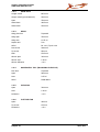


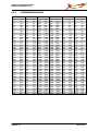


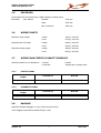


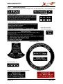
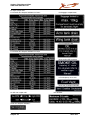


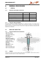


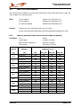
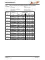

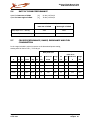

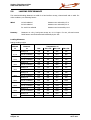

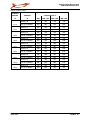

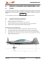


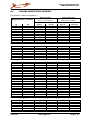

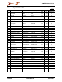

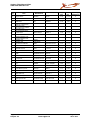


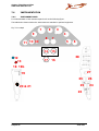


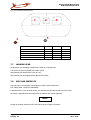


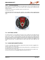


![U.S. Version [Last Updated on: Jun 13th, 2014]](http://vs1.manualzilla.com/store/data/005873845_1-0370c7761d3b42576ec2ae1fd24c9e75-150x150.png)