1
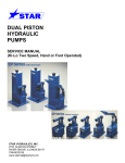
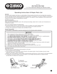
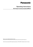
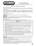
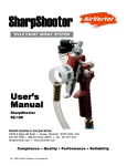
DUAL PISTON
HYDRAULIC
PUMPS
SERVICE MANUAL
(Hi-Lo Two Speed, Hand or Foot Operated)
.
STAR HYDRAULICS, LLC
2727 CLINTON STREET
RIVER GROVE, ILLINOIS 60171
708/453/3238
www.starhyd@starhyd.com
MAINTENANCE
In servicing hydraulic units, cleanliness is of the utmost importance.
A clean work place and proper tools
are necessary to insure efficient and
effective repair. Special tools can
be furnished on request.
A
E
C
NOTE: Please specify pump model
number when ordering parts. If you
are not sure of your pump model
number, call the factory and request
a pump model identification sheet be
faxed or e-mailed to your. Pump parts
lists are also available for your model.
A
ONLY ON
CP-15
E
D
D D
C-B
D
B
D
PRESSURE
PORT
D
Typical assembly drawing of two speed pump showing
sectional view location.
TROUBLE
Pump will not hold pressure
Pump fails to supply pressure
Pump piston does not draw a full charge.
(This is evident by a cushion effect at the
top of the pump stroke)
POSSIBLE CAUSE
CORRECTIVE REPAIR
INSTRUCTIONS
1.
Release valve ball not seating properly
Refer to “Release Valve” notes
2.
Ball valves not seating properly
Refer to “Pump Valve” notes
3.
Overload valve ball not seating properly
Refer to “Overload Valve” notes
4.
Large piston unloading valve seal faulty
Refer to “Large piston unloading valve”
1.
Lack of oil
2.
Air bound pump
3.
Release valve ball not seating properly
4.
Small ball in valve circuit not seating properly
5.
Overload valve ball not seating properly
6.
Large piston unloading valve seal faulty
1.
Air bound system
Refer to “Air Bleeding” notes
2.
Lack of oil
Refer to “Oil” notes
Refer to “Oil” notes
Refer to “Air Bleeding” notes
Refer to “Release Valve” notes
Refer to “Pump Valve” notes
Refer to “Overload Valve” notes
Refer to “Large piston unloading valve”
Pump piston raises by itself under pressure
Large ball in ball valve circuit not seating properly
Refer to “Pump Valve” notes
Pump functions properly but will generate
only a given pressure below its normal
pressure maximum
Overload valve not properly set
Refer to “Overload Valve” notes
Large piston unloading valve not set properly
Refer to “Large piston unloading valve”
Pump fails to supply greater output at no
load than under load.
Air Bleeding
Air accumulation in a hydraulic system will cause erratic action. This may appear as pump failure to the
inexperienced user. For this reason, it is advisable to air bleed each pump before attempting to operate. To
remove air from the pump, open release valve with the pump in an upright position. Operate the pump slowly
through the full piston stroke about a dozen times. Close the release valve. Pump should be ready for use.
Oil
If the pump fails to operate, check the oil level before attempting any repairs.
The maximum fill level is 1 ½” below the inside of the reservoir cover.
CAUTION: Use only hydraulic oil when refilling. NEVER USE BRAKE FLUID.
Pump Piston
Leakage of oil around the pump piston may indicate worn or damaged piston packings.
To replace packings:
a)
b)
c)
d)
e)
Remove the piston actuating linkage
Remove the piston. (See piston section drawing A-A)
Remove all packings. (see piston section drawing A-A)
Clean all parts and dry with compressed air.
Install new packings, wipers, and static seals making sure that packing seal lips are face down toward the
pressure. (Lubricate each part into clean hydraulic oil before assembly)
f) Open the release valve (to allow air to bleed from the piston barrel back to the reservoir) and insert the piston.
g) Replace piston linkage.
h) NOTE: With release valve open, stroke pump about a dozen times to bleed air completely from the pump.
Pump Valves
If the pump fails to supply pressure or if the pump piston is under pressure at all times, the pump valves may need
cleaning. Stand pump in an upright position. Remove the valve plug and seal. Tilt the pump to remove valve
springs and balls. Allow oil to drain from the reservoir through these valve holes to wash foreign matter from the
valve cavity. Lay pump on its side to clean and inspect valve chamber. Be careful not to mar or nick the ball valve
seats. Clean the valve balls and springs in solvent. Replace rusted or corroded balls. Do not stretch the ball
springs. To reassemble, insert in sequence, the small ball, small spring, large ball, and large spring into the
cleaned chamber. Finally, screw in valve seal plug. Note that the seal kit contains the new style valve plug and
seal. This procedure should be carried out in all ball valve circuits. If the valves fail to operate properly after they
have been cleaned, it may be necessary to reseat the valve balls. Remove the springs and tap each ball lightly in
its respective seat using the ¼” ball seating tool (CP13-42) for the small ball and the 3/8” ball seating tool (CP13-43)
for the large ball. Remove balls to make sure they are not stuck to the seats. Reassemble pump valves as before.
See “Air Bleeding” instructions before attempting to operate the pump.
Release Valve – Cam Type
If the pump fails to lift or hold a load, the release valve may be
dirty. From back of pump remove the release valve plug, release
ball spring and 3/8” release ball. From the front, remove the
release lever pin, release lever and release plunger and seal.
Clean release valve chamber and inspect the ball seat. If
necessary, re-seat the release ball by tapping it lightly on the ball
seat, using the 3/8” ball seating tool (CP13-43). Clean plunger
and inspect the plunger packing and replace if necessary. To
reassemble, insert the ball, ball spring, and release valve plug.
Lubricate the release plunger packing with hydraulic oil and
carefully insert into the plunger chamber. Re-install the release
lever and lever pin. See “Air Bleeding” instructions before
attempting to operate the pump.
Release Valve – Screw Type
If the pump fails to lift or hold a load, the release valve may be dirty.
Remove the release screw, release valve seal and 9/32” release valve
ball. Clean and inspect valve seat and screw. A slight depression in the
end of the screw is not harmful. Screws with excessive deformation
should be replaced. Re-seat the release ball using the ¼” ball seating
tool (CP13-42). To reassemble, insert the release valve packing using
inserting tool P1A-40. Reinstall the release screw. See “Air Bleeding”
instructions before attempting to operate the pump.
Overload Valve
If the pump fails to lift or hold a load after the release valve and pump
valves have been checked, the overload valve may be dirty. To clean the
valve, remove valve plug and valve plug seal. Using a screwdriver,
remove the overload valve screw, valve spring, valve plunger and steel
ball. Clean and inspect valve cavity. If the ball seat is marred, re-seat
the overload ball by lightly tapping the ball on seat using tool (CP13-45).
Remove the ball to prevent sticking. Reassemble the ball, plunger, spring
and valve screw. Connect a pressure gage to the pressure outlet. Stroke
the pump to obtain maximum desired pressure. Turn the valve screw
clockwise to increase the pressure reading and counter-clockwise to
reduce the maximum reading. After valve is set properly, replace valve
plug. Note that the seal kit contains the new style valve plug and seal.
See “Air Bleeding” instructions before attempting to operate the pump.
Large Piston Pump Relief Valve
If the pump fails to lift faster under no load than it does under heavy load,
the large piston unloading valve may be dirty. This valve is covered with
a sealing compound to prevent tampering. Remove the sealing
compound, valve screw, spring and plunger with seals. Use threaded
socket tool (CP13-41) to remove plunger. Clean and inspect the valve
cavity. Inspect the plunger packings and replace if necessary. To
reassemble, lubricate the plunger seals with hydraulic fluid and carefully
insert it back into the valve cavity taking care not to damage the seals.
Reassemble the spring and valve screw. Tighten the screw to obtain the
desired effort on lever bar at large piston change-over point. If the screw
is tightened too far it will restrict the unloading valve movement and cause
excessive handle effort throughout the high pressure cycle.