1
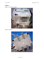
Sonic Water Conditioning System, Model Sonical Tested under UL 979 Standard for Safety Water Treatment Appliances - First Edition; May 5, 2011 and CSA/CAN 22.2 No. 68-09, Motor-operated Appliances, February 2010 File: E212505 MET Report: 37385 Approved: September 18, 2013 Applicant: Go Green Technologies Corp. 115 Hurley Road Oxford, CT 06478 USA Prepared By: MET Southeast 901 Sheldon Drive Cary, NC 27153 USA For: MET Laboratories, Inc. 914 West Patapsco Avenue Baltimore, Maryland 21230-3432 (410) 949-1802 © Copyright 2013 This report shall not be reproduced except in full, without the express written consent of MET Laboratories, Inc. MET Listing MET Recognition MET Classification Mexican Certification MET-C Listing MET-C Recognition MET-C Classification Page 1 of 16 File: E212505 MET Report: 37385 Table of Contents CHANGE RECORD ................................................................................................................................................... 3 DESCRIPTION ........................................................................................................................................................... 4 GENERAL REQUIREMENTS .................................................................................................................................. 5 MARKINGS ................................................................................................................................................................. 7 APPLICANT’S RESPONSIBILITIES ...................................................................................................................... 9 PRODUCT MODIFICATION ........................................................................................................................................... 9 MANUFACTURING AND PRODUCTION-LINE TESTS AND DOCUMENTATION PERFORMED BY MANUFACTURER. ......... 10 CRITICAL COMPONENTS .................................................................................................................................. 111 FIGURES ................................................................................................................................................................. 122 TESTING CONSIDERATIONS ............................................................................................................................ 155 CONCLUSION ........................................................................................................................................................ 166 Page 2 of 16 File: E212505 MET Report: 37385 Change Record Change Number Description Page 3 of 16 Approval Date Project Number File: E212505 MET Report: 37385 Description Product(s) Covered: Water Treatment Appliance, Model Sonical The Model Sonical system consists of the electrical enclosure that supplies a SELV (Non-hazardous) voltage to the water conditioner. The conditioner is protected from overheating if water is not running through it by a thermostat. Electrical Rating: 120 Vac, 60 Hz, 5 A, 78 W Engineering Considerations (Not For Field Representative's Use): The Water Treatment Appliance, Model Sonical has been investigated in accordance with UL 979 Standard for Safety Water Treatment Appliances - First Edition; May 5, 2011, and CSA/CAN 22.2 No. 68-09, Motor-operated Appliances February 2010. Note to Field Representative: None Operation/Service Instructions: Operations and Service instructions are provided with the equipment. Page 4 of 16 File: E212505 MET Report: 37385 General Requirements Scope: The requirements contained within this section apply to all products contained within this Follow-Up Service Report File. Exceptions, if any, shall be noted within the body of the report. Definitions: (as defined or used in the context of the standard) Term Definitions SELV: Safety Extra Low Voltage PCB: Printed Circuit Board Listed/Recognized Component: A component evaluated to the applicable U.S. standards by a Nationally Recognized Testing Laboratory (NRTL). Certified Component: .A component evaluated to the applicable Canadian standards by a Certification Organization (CO). Listee: Applicant Measurements: All dimensions indicated in the body of this report are approximations unless otherwise indicated. Corrosion Protection: All corrosive metals shall be provided with a means to protect from corrosion. Acceptable methods include painting, plating and galvanizing. Dissimilar metals shall not be employed where reliable continuity is required. Soldered Connections: All soldered connections shall be made mechanically secure before soldering. Tack soldering is not acceptable. Acceptable forms of mechanical securement include: A) Lead is inserted through an eyelet or opening of a terminal block prior to soldering. B) Lead is inserted into a U or V shaped slot in the terminal prior to soldering. C) Lead is wrapped around a terminal post prior to soldering. D) Lead is tied to adjacent lead with wire tie-wrap near termination point. Electrical Connections: All electrical connections other than soldering shall be provided with positive detent, crimp type insulated Recognized Component connectors suitable for the voltage and temperatures involved. They shall be sized for the wire and mounting terminations. Where hazardous voltage or energy is involved, all wire connections to connectors shall employ a recognized method of double securement. Where fork-type lugs are used, they shall be snap-on or up-turned lug type. Mechanical Assembly: All parts shall be secured by welding, bolts/nuts with lock or star washers, or thread forming screws. Operation/Service Manual: Unless otherwise noted, each unit shall be provided with an operations and installations manual. They shall include the following: “GROUNDING INSTRUCTIONS – This appliance must be grounded. In the event of a malfunction or breakdown, grounding will reduce the risk of electric shock by providing a path of least resistance for electric current. This appliance is equipped with a cord having an appliance-grounding conductor and a grounding plug. The plug must be plugged into an appropriate outlet that is installed and grounded in accordance with all local codes and ordinances.” “WARNING – Improper connection of the appliance-grounding conductor can result in a risk of electric shock. Check with a qualified electrician or service representative if you are in doubt whether the appliance is properly grounded. Do not modify the plug provided with the appliance; if it will not fit the outlet, have a proper outlet installed by a qualified technician.” Page 5 of 16 File: E212505 MET Report: 37385 General Requirements (Continued) Creepage and Clearances: Installation II Category Between Primary Primary and and Ground SELV Pollution Degree Voltages up to (Vrms) 250 250 2 Insulation Required Basic Reinforced Material IIIb Group Creepage Clearance (Over Surface) (Through Air) 1.5 mm 3.0 mm 3.0 mm 6.0 mm Internal Plastics: Shall be a Recognized/Certified Component, Plastic, rated minimum 94V-2. PCB: Shall be a Recognized Component, rated minimum 94V-2 and 105C. Tubing and Sleeving: Shall be a Listed/Recognized/Certified Component, rated minimum 300V, 80°C minimum, 94V-2, unless otherwise noted. Wire Connectors: (Various crimp-type) Shall be Listed/Recognized/Certified Components sized for the wire and mounting terminations. Both the wire insulation and the conductor shall be crimped. Fuseholder: Operator accessible fuseholders, when provided, are connected to the ungrounded conductor(s) of the primary circuit. Internal Wiring: All internal wiring and connections are properly jacketed or enclosed within the equipment. Wiring is routed and secured to reduce the possibility of stress being transmitted to electrical connections, as necessary. All internal conductors in the secondary circuits are routed away from primary circuit conductors and from uninsulated live parts. There is no internal wiring subject to contact by the user when the product is employed as intended. The internal wiring is acceptable for conditions of service to which it will be subjected. Internal conductors consist of Recognized Component AWM insulated individual conductors; sized in accordance with the National Electric code and Canadian Electrical code, as may be applicable for the current expected in the conductor, rated VW-1, 300V, 90C, and signal level ribbon wiring of flammability rating VW-1. Interconnecting Cords and Cables: Flexible telecommunication cord and cable assemblies employed for interconnection between components are to be rated for and comply with temperatures, exposure to oil or grease and other conditions of service within the environment the product is to be utilized. Terminal Block: When provided, shall be secured to the inside of the enclosure with a screw. Wire Binding Screw: When intended for connection of the protective grounding conductor shall have a green-colored head that is hexagonal, slotted, or both. Page 6 of 16 File: E212505 MET Report: 37385 Markings Etching, molding, die-stamping, silk-screening, stamped-, or etched-metal labels secured by rivets or screws are considered permanent. Recognized/Certified Component, Marking and Labeling Systems, suitable for the surface to which it is applied is also considered permanent. Per the Canadian Electrical Code described in CSA C22.0 General Requirements, Canadian product certification requires warning/cautionary markings in both English and French languages. It is the Applicant’s responsibility to provide the listed Bilingual Markings shown below in accordance with the Canadian regulatory requirements. Each product is to be permanently marked with the following information: a. The MET Mark (refer to MET Applicant Contract), with the applicant/listee name or alternate listee name as identified within this report, trade name or trade mark, product model number, and a date of manufacture or serial number. b. Method of applying the MET Mark: Direct Imprinting Purchasing Labels from MET Laboratories, Inc. Approved MET Mark: Listed Complies with UL 979 CSA/CAN 22.2 No. 68-09 E212505 c. A rating label adjacent to the inlet connector identifying the voltage, current or power, frequency, fuse ratings, and fuse rupturing speed for the equipment. d. Near each terminal and control, there shall be a marking to identify the function. e. Signal words such as “CAUTION” or “WARNING” shall be no less than 0.11 inches (2.8 mm) high and other text of a safety marking shall be no less than 0.06 inches (1.6 mm) high and contrasting in color. f. The protective earthing terminal shall be identified with the IEC 417, No. 5019 Protective Earthing marking. g. Near each replaceable fuse, the word “CAUTION” and the following or equivalent wording: “TO REDUCE THE RISK OF FIRE, REPLACE ONLY WITH SAME TYPE ___A-___V FUSE.” h. The following wording shall be used for the French equivalent marking: “ATTENTION: POUR NE PAS COMPROMETTRE LA PROTECTION CONTRE LES RISQUES D’INCENDIE, REMPLACER PAR UN FUSIBLE DE MÊME TYPE ET DE MÊMES CARACTÉRISTIQUES NOMINALES.” i. Connect only to a circuit that is protected by a ground-fault circuit interrupter (GFCI). j. “WARNING” “Risk of Electric Shock. Disconnect power before servicing” k. The following wording shall be used for the French equivalent marking: "AVERTISSEMENT" "Risque de choc électrique. Coupez l'alimentation avant l'entretien " Markings (Continued) Page 7 of 16 File: E212505 MET Report: 37385 l. “Indoor Use Only” or similar m. The following wording shall be used for the French equivalent marking: “Usage intérieur uniquement“ n. Appliances having provision for connection to a potable water supply shall be marked with the following or equivalent: “WARNING: IF CONNECTION IS MADE TO A POTABLE WATER SYSTEM, THE SYSTEM SHALL BE PROTECTED AGAINST BACKFLOW.” o. The following wording shall be used for the French equivalent marking: "AVERTISSEMENT: si la connexion est faite à un système d'eau potable, le système doit être protégé contre le reflux." Page 8 of 16 File: E212505 MET Report: 37385 Applicant’s Responsibilities Product Modification Minor product modifications by the manufacturer may be allowed using the following guidelines: 1. Components identified in this report as "Listed, Recognized, or Certified" and NOT identified with a manufacturer name or part number may be exchanged with an alternate "Listed, Recognized, or Certified" component of equivalent value. Example: Appliance Inlet Connector - Listed/Certified Component, IEC 320 style male connector, rated 250 volts and 20 amperes. Mechanically secured to the front panel with screws and locking washers. This inlet connector may be replaced with any Listed/Certified inlet connector with the same ratings as stated and where mechanical securement is maintained. 2. Components identified by a manufacturer name, part number, or with specific comments, (such as AC only, indoor use only, approved for use in this product only), may NOT be replaced or modified without prior approval from MET Laboratories. Example: Circuit Breaker - Recognized/Certified Component, ABCD Co. P/N XYZ123, rated 250 volts maximum, 50/60 Hz, 25 full-load amperes, 31.3 trip amperes. Toggle handle marked with IEC on/off symbols. Mechanically secured to the front panel with screws and locking washers. This circuit breaker can NOT be modified or changed without prior approval by MET Laboratories, Inc. For your convenience a Project Amendment Request (PAR) form is available for download at http://www.metlabs.com/Portals/0/PDF/Par.pdf. For any changes related to product construction, manufacturing locations, if the product is intended to be marketed/sold under an alternate name or model number than that originally listed, or any issues which would require notification or change in the status of this file, please complete the form and return to MET Laboratories, Inc. following the instructions provided on the form. If you are terminating or temporarily suspending production of this product for an extended period, please send a letter on company letterhead to: MET Laboratories, Inc. Attn: Follow Up Services Department 914 West Patapsco Avenue Baltimore, Maryland 21230 USA Fax: (410) 354-3313 Page 9 of 16 File: E212505 MET Report: 37385 Manufacturing and Production-Line Tests and Documentation performed by Manufacturer. All certified products are required to be subjected to production line testing as indicated below: Dielectric Voltage-Withstand Test: Each complete end product shall be capable of withstanding, without electrical breakdown, the application of a continuous sinusoidal or direct current voltage between uninsulated live parts and accessible dead metal parts that are likely to become energized in accordance with one of the following methods. Circuit Rating Circuit Tested Voltage (VAC) Method A Voltage (VDC) Time (sec) Voltage (VAC) Method B Voltage (VDC) Time (sec) Up to 250 V Primary to Ground 1000 1414 60 1200 1700 1 Up to 250 V Primary to Secondary 1000 1414 60 1200 1700 1 Grounding Continuity Test: Each complete product shall be tested to determine grounding continuity between the grounding pin or terminal of the attachment plug and the accessible dead metal parts that are likely to become energized. The grounding contact of each receptacle, and other means for grounding on the load side, shall be included in this test. Compliance is to be determined by any appropriate device, such as an ohmmeter, or a battery and buzzer combination, applied between the points under test. Documentation: The manufacturer is required to record the production line test results. The data recorded is to include the type of test, date of test, serial number of the product, indications of pass, fail, or retest, test equipment utilized, calibration date of test equipment utilized, and the initials or signature of the test technician. Test records shall be required to be maintained from factory follow-up audit to factory follow-up audit and must be available for the inspectors’ review. Records may be in the form of travelers, logs, computer files, or other such suitable documentation method. Page 10 of 16 File: E212505 MET Report: 37385 Critical Components Object/ Parts No. Manufacturer/ Trademark Description Model Sonical is comprised of the wall mounted enclosure and the water conditioner. 1/1 Enclosure Gewiss GW44217 Type 1 enclosure 1/2 Fuseholder Cooper Bussmann HPG or HPD UL94V-0 Not seen Fuse Cooper Bussmann AGX-2 250 Vac, 2 A, 5 x 20 mm 1/3 Strain Relief (2 provided) Heyco CTS Rated 94V-2, 30 – 100 oC 1/4 Cable Gland Heyco Flex RLTF 11 Rated 94V-2,\ 30 – 100 oC 1/5 Supply Cord Set Various SVT 16/3, 125 Vac, 13 A, 105 oC 2/1 Transformer Ensign P413 2/2 Bridge Rectifier Won-Top Electronics KBPC40 Input: 100-230 Vac, 50/60 Hz Output: 5 & 12 Vac, Class F 120 Vac, 50 A UL 1557 UL Recognized 2/3 Heat shrink tubing Alpha Wire FIT-221 600 V, 125 oC UL 224 UL Recognized 2/4 Terminal Block Various Various 300 V, 5 A min. UL/cUL Recognized 3/1 Water Conditioner Go Green Sonical 10 Vdc, 1.8 A UL 1059, CSA-C22.2 No. 158 N/A Not seen Thermostat NTE KSD301 10A, 250VAC UL 873, CAN/CSAE60730-2-9 UL/cUL Recognized Not seen Silicon Adhesive Momentive Performance Materials RTV108 -60 oC to 205 oC UL 746C UL 94, UL Recognized Figure /Item No. 1 Type/ Model Technical Data Page 11 of 16 Standard (Edition / year) UL 50, CSA-C22.2 No. 94.1 UL 4248-1 Class C, CSA-C22.2 No. 248.1 UL 284-1, CSA-C22.2 No. 248.1 UL 514A, CSA-C22.2 No. 18.3 UL 514A, CSA-C22.2 No. 18.3 UL 817, CSA-C22.2 No. 21 UL 1446, CAN/CSAC22.2 No. 0 Mark(s) of Conformity Secured Method CSA Certified Secured to wall by screws UL/cUL Recognized Secured to enclosure by nut UL/cUL Listed Secured in fuseholder by fit Secured to enclosure by nut Secured to enclosure by nut Secure to enclosure with strain relief Secured to mounting plate with screws UL/cUL Recognized UL/cUL Recognized UL/cUL Listed UL/cUL Recognized N/A Secured to mounting plate with screws Secured on internal wiring by fit Secured to mounting plate by screw Secures into building water system by threads Secure to conditioner body with silicone and screws. Secures thermostat to conditioner body File: E212505 MET Report: 37385 Figures Figure 1. Overall View of Sonical Rear View of Sonical Page 12 of 16 File: E212505 MET Report: 37385 Figures (Continued) Figure 2. Internal view Page 13 of 16 File: E212505 MET Report: 37385 Figures (Continued) Figure 3. Water Conditioner Page 14 of 16 File: E212505 MET Report: 37385 Testing Considerations A sample of the Water Conditioning System, Model Sonical was subjected to the following test program with satisfactory results. All tests were conducted in accordance with UL 979 Standard for Safety Water Treatment Appliances - First Edition; May 5, 2011 and CSA/CAN 22.2 No. 68-09, Motor-operated Appliances, February 2010 Only these tests were considered necessary due to engineering considerations. Detailed test results are on file at MET Laboratories under project number 37385 TESTS CONDUCTED: 1. Input 2. Leakage Current 3. Humidity Preconditioning with 4. Leakage Current following Humidity 5. Dielectric Voltage –Withstand following Humidity 6. Grounding Resistance 7. Operational Test 8. Strain Relief 9. Push Back Relief 10. Temperature 11. Dielectric Voltage Withstand 12. Abnormal Operation 13. No Water Test 14. Impact 15. Mold Stress Relief Distortion 16. Output or Interconnecting Cable Strain-Relief Test 17. Starting Test Page 15 of 16 File: E212505 MET Report: 37385 Conclusion The product covered by this report has been tested, examined, and found to comply with the applicable requirements of UL 979 Standard for Safety Water Treatment Appliances - First Edition; May 11, 2005, and CSA/CAN 22.2 No. 68-09, February 2010. Prepared By: Dayna Wittman Sr. Project Engineer, MET Partner Laboratory Reviewed By: Bill Bisenius Sr. Project Engineer, MET Partner Laboratory Approved By: Rick Cooper Director of Laboratory Operations, Safety Laboratory Last Page Page 16 of 16